WIRELESS GLASS
BREAK
DETECTOR
«STEKLO-3RK»
1 Introduction
1.1 The wireless glass break detector «Steklo-3RK» (hereinafter, the Detector)
is intended for detecting destruction of all known kinds of construction glass:
common, quenched, patterned, armored, multilayer and laminated with polymer
film, glass units, as well as hollow glass blocks installed in structural units
(openings) and/or interior elements of closed spaces.
1.2 The Detector transmits status messages via two-way communication in
the 433.05 to 434.79 MHz frequency range to the control panel (hereinafter, CP)
supporting the «Rielta-Contact-R» wireless communication protocol:
- «Norm» – under the absence of any impact on the protected glass,
- «Alarm» – in case of impact on the protected glass detection,
- «Tamper» - in course of case or wall tampering,
- «Main battery discharge» – if main power supply battery voltage drops lower
than 2,5-0,2 V,
- «Backup battery discharge» – if backup power supply battery voltage drops
lower than 2,5-0,2 V.
1.3 The Detector provides case and wall tamper protection.
1.4 The Detector may be installed on the wall, ceiling or on a pier between the
monitored glass and curtains.
1.5 The Detector ensures remote monitoring of controlled glazed structures
of any shape.
1.6 The Detector provides multilevel microprocessor signal processing and
functional self-test.
1.7 The Detector adjusts the sensitivity depending on the interference situation
at the monitored facility.
1.8 The Detector operates at one of 8 possible operating frequency numbers.
Each number contains two operating frequencies: the main and the reserve one.
1.9 The Detector automatically switches over backup frequency in case of
impairment of interference conditions at the main operating frequency.
1.10 The Detector is able to switch on and off an identification and status LED
indication by the CP relevant command.
1.11 The Detector the following rates of control radio exchange may be
assigned: 10 s,15 s, 30 s, 60 s ,300 s, or 600 s during binding procedure with
CP. Alarm messages are transmitted immediately.
1.12 The Detector is powered by two batteries, the main – CR123A and the
backup one – CR2450.
1.13 The Detector refers to single-zone (single-address) detector type.
2 Field of Application
The Detector can be applied in offices, shops, museums, exhibition halls,
banks, accommodation rooms, etc.
3 Specifications
Table 1
Parameter Value
Maximum detection range 6 m
Angle of coverage 120о
Installation height at least 2 m (see Figures 3 – 7)
Operating temperatures range
from minus 20 to +55
°С
Relative air humidity at 25 °С
up to 98 %
Broadcast period (programmed during the
CB binding) 10 sec to 10 min
Probability value of glass destruction at least 0.9
Warm-up time, not more than 30 s
Sensitivity value ( at a signal duration 20 ms
or more):
- on first operating frequency
- on second operating frequency
(80 ± 3) dB
(90 ± 3) dB
Weight (without power batteries) maximum 0.1 kg
Dimensions
maximum 105 x 50 x 40 mm
Battery life (under normal conditions, and messa-
ges transmitting period not less than 60 sec)
up to 5 years
IP rating IP30
Mean time-to-failure, not less than 60 000 h
Average service life, not less than 8 years
4 Scope of Delivery
Each Detector unit package contains the items listed in Table 2.
Table 2
Name Qty
Wireless glass break detector «Steklo-3RK»
Wall plug 5x25
Screw 3-3x30.016
CR123A lithium power-supply battery
CR2450 lithium power-supply battery
Wireless glass break detector «Steklo-3RK». Installation Guide
1 pc.
2 pcs.
2 pcs.
1 pc.*
1 pc.*
1 copy
* - Supplied optionally
Installation Guide
5 Binding with the CP
The binding procedure is intended for the logging of the Detector in the CP
and exchange of service information.
1. Observing the polarity install the СR2450 backup power supply battery into
the holder located on the reverse side of the Detector PCB, thereafter install
the СR123А main power supply battery. If batteries are already installed, then
remove the isolators.
2. LED indicator blinking green displays the Detector readiness to the binding
procedure. In case of the LED indication absence, the Detector should be trans-
ferred to the «Binding» mode by closing the «RESET» contacts until the green
LED indicator starts blinking.
3. In case of successful binding with the CP (repeater), the LED indicator
blinks red for 1 s.
Note – The zone number is determined in accordance to the CP user manual.
The binding procedure is limited up to 70 sec, whereupon the Detector transfers
to the sleep mode. To restart the «Binding» mode close «RESET» contacts for
a short time.
6 LED Indication
Table 3
Detector Status
Indication Note
«Norm» LED indication is OFF
«Binding» mode LED indicator blinking green peri-
odically
The Detector logging
in the CP
«Alarm»
LED indicator single time blinking red
«Tamper» see section «Communication Quality Appraising»
«Identification» LED indicators alternate blinking red
and green
Upon the relevant
command from the CP
«Adjustment»
LED indicator blinking green every 1 s
Upon the DIP-switch
3 is ON
«Interference» the LED indicator lights up green During the interference
time
Norm LED indication is OFF
Communication
quality see section «Communication Quality Appraising»
7 Choosing the Detector Location
Before installing the Detector, get acquainted with the following requirements:
- it is recommended to install the Detector at least 2 m height (see examples
of installation in Figures 3 – 7);
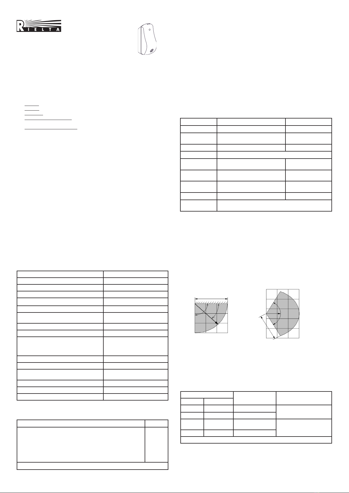
- when choosing the place of installation, the Detector detection zone location
must be taken into account (Figure 1);
- distance (L) between the Detector and the farthest point of the monitored
glass should not exceed 6 m;
- during joint operation with an active ultrasonic Detector, distance between
Detectors must be not less than 1 m;
- the entire surface of the monitored glass should be available within the direct
visibility of the Detector.
The Detector must be located within the radio visibility zone of its repeater;
therefore, it is recommended to estimate the quality of communication with the
CP (repeater). Top View
Side View
L
45о
120
о
Figure 1 – Detection Pattern
8 Communication Quality Appraising
To estimate the communication quality:
1 Place the Detector on its installation place;
2 Press the Detector tightly to a hard surface in order to close the tamper output;
3 Remove the Detector cover. Whereupon the Detector transmits a tamper
message (the LED indicator lights red) and then the LED indicator displays com-
munication quality with the CP by a three-grade scale (see Table 4).
Table 4
LED Indication Communication
Quality Appraisal Recommendations
Color Mode
Green Three blinks Excellent
Install the Detector at this
place
Green Two blinks Good
Green One blink Communication
established
Choose another place
for installation or use a
repeater*)
Red Four blinks No communication
*) – «Ladoga-RK» system repeater
9 Installation of the Detector
Remove the cover and PCB of the Detector and fasten the Detector with the
help of screws. Choose the place of the Detector installation and mark out its
fastenings using the Detector base (
Figure
2) for the purpose. Fix the base by the
screws (supplied).


