manuals.online logo
Brands
  1. Home
  2. •
  3. Brands
  4. •
  5. jablotron
  6. •
  7. Security Sensor
  8. •
  9. jablotron JA-151ST-A User manual

jablotron JA-151ST-A User manual

JABLOTRON ALARMS a.s.
Pod Skalkou 4567/33 46601 Jablonec n. Nisou
Czech Republic www.jablotron.com
||
|
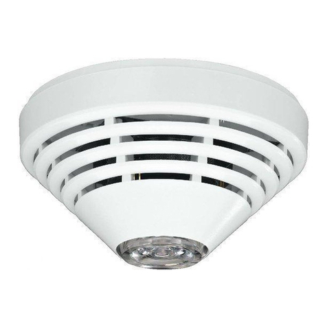
The JA-151ST-A Wireless combined smoke and heat detector
The JA-151STWireless combined smoke and heat detector 1/3 MLW25101
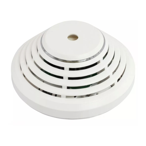
The JA-151ST-A is a component of the JABLOTRON 100 alarm
system. It is used to detect fire hazards in the interior of residential
or commercial buildings. The detector is powered by three LR6 type
alkaline AA batteries which are not included. We recommend buying
them with the detector. The detector indicates a fire hazard visually
using the built-in LED indicator and acoustic signalling.
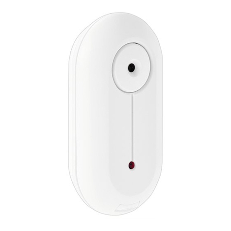
The JA-151ST-A can acoustically indicate any other alarm such
as intrusion or tampering. The detector consists of an optical smoke
detector and a heat detector. The optical smoke is very sensitive
to large dust particles which are present in dense smoke. It is less
sensitive to smaller particles generated by the combustion of liquids
such as alcohol. That is why the fire detector also contains a built-in heat
detector which has a slower reaction but is capable of detecting fire with
a small amount of smoke. The detector has a status reaction (reports
triggering and switching to stand-by mode). The product is not designed
to be installed in industrial premises. The detector should be installed
by a trained technician with a valid manufacturer’s certificate.
Detector location
The smoke detector must be installed in places where smoke can
easily drift into the detector owing to natural thermal circulation (usually
towards the ceiling). The detector can be used only in enclosed
interiors. It is not suitable for areas where smoke can disperse and cool
down (for example rooms with high ceilings above 5 m) – the smoke
would not reach the detector position.
The detector must always be placed in the section leading
to the exit of the building (escape route), see Fig. 1. If the building has
a floor area greater than 150 m2, installation of an additional detector
in some other suitable place is required, see Fig.2.
1
2
3 4
5
Fig. 1
1
2
3 4
5
6
Fig. 2
1
2
3
6
Fig. 3
In multi-storey flats and family houses the detector should be installed
above the stairs. It is recommended to place additional detectors in all
rooms where people sleep. See Fig 3.
Installation on level ceilings
Place the detector in the centre of the room if possible. The detector
must not be recessed into the ceiling due to the possible existence
of a warm layer of air on the ceiling. Never place the detector in the
corner of the room, there is an insufficient circulation of air. Always
install the detector at least 0.5 m distance from the corner, see Fig 4.
Installation on sloping ceilings
If the ceiling is not suitable for mounting on a level surface (e.g.
a room under a roof ridge) the detector can be installed as in Fig. 5.
Walls, partitions, barriers and lattice ceilings
The detector must be installed at least 0.5 m away from any wall
or partition. A narrow room with a width of less than 1.2 m requires the
detector(s) to be placed in the middle third of its width. If a room is separated
into sections with furniture, racks or semi partition walls which do not
reach the ceiling, the space is considered to be fully separated if the
gap between the top of these and the ceiling does not exceed 0.3 m.
A free space of at least 0.5 m is required under and around the detector.
Any irregularities of the ceiling (e.g. girders) exceeding 5 % of the ceiling height
should be considered a wall and the limitations mentioned above should apply.
Ventilation and air circulation
The detectors must not be installed directly by ventilation or air
conditioning vents. In the case of air being supplied through
a perforated ceiling, there must be no perforation within the 0.6 m radius
of the detector in all directions.
Avoid installing the detector in the following locations:
Places with poor air circulation (niches, corners, apexes
of A-shaped roofs, etc.)
Places exposed to dust, cigarette smoke or steam
Places with over-intense air circulation (close to ventilators, heat
sources, air conditioning outlets, etc.)
In kitchens and humid areas (because steam, smoke or oily fumes can
cause false alarms or reduce detector sensitivity).
In areas with lots of small insects, which may cause false alarms
Warning: Most false alarms are caused by improper detector location.
See the CEN/TS 54-14 standard for detailed installation guidelines.
Installation
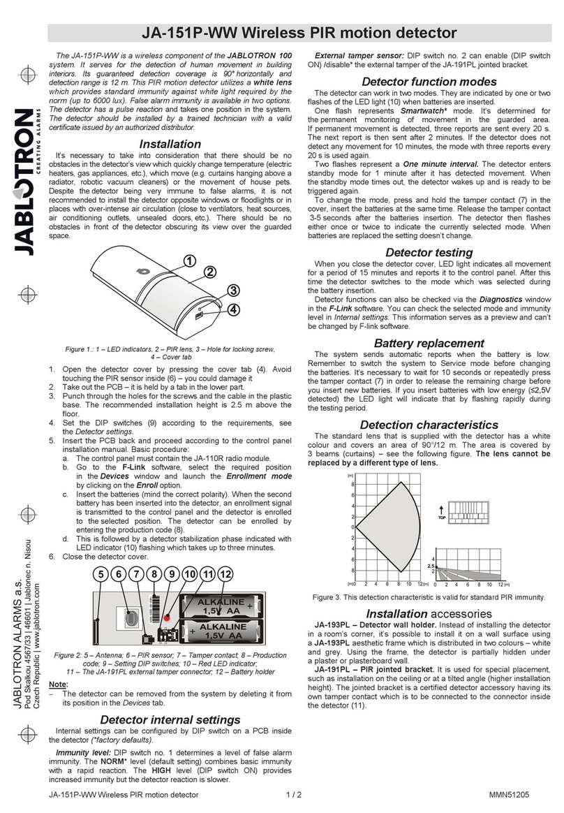
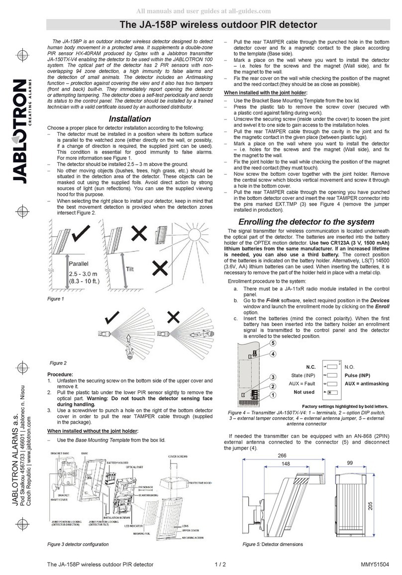
When installing the detector, abide by the procedures recommended
in the previous paragraphs.
Fig 6: 1– opening the detector cover; 2 – closing the detector cover;
3 – optical status indication; 4 – arrow showing where to insert the detector;
5 – production code; 6 –external antenna connector; 7 – battery holders;
1. Open the detector cover, by turning it anti-clockwise (1)
2. Attach the plastic base to the selected place using screws
3. Proceed according to the control panel installation manual.
Basic procedure:
a. Go to the F-Link program, select the required position
in the Devices window and launch enrollment mode
by clicking on the Enroll option.
0.5m
TOP
Fig 4
0,9 m
Fig 5
center of the room, the most suitable location.
acceptable location
The JA-151ST-A Wireless combined smoke and heat detector
The JA-151ST Wireless combined smoke and heat detector 2/3 MLW25101
b. When you insert all batteries into the detector, an enrollment
code is sent to the system which is confirmed with a short
flash of the LED indicator (3).
4. Insert the detector into the plastic base. The detector can
be inserted into the plastic base in one position only. It is marked
with arrows (4) on both plastic parts. Close the detector cover
by turning it clockwise (2).
5. Set the detector according to the Detector setting chapter.
Note:
In order to perform enrollment via F-Link easier, we recommend
removing the production code sticker, placing it on some paper
and writing down the location before installing the detector
The detector can also be enrolled into the system by entering its
serial number (6) in the F-Link program. All numbers stated under
the bar code shall be entered (for example: 1400-00-0000-0001).
When necessary, the AN-868 external antenna can be connected
to the detector to boost communication.
Detector setting
The detector properties can be set up in the Devices window
in the F-Link program (*indicates factory settings).
The Reaction option in the Devices tab allows you to set the type
of reaction of the system to the activation of the enrolled detector.
To set the detector’s behaviour, click on the Internal settings button
which will open up a dialogue window.
Reaction: Determines whether the detector will react to Smoke only,
Heat only, Smoke or heat, Smoke and heat simultaneously, see
the following table.
Smoke only EN 14604; EN 54-7
Heat only EN 54-5
*Smoke or heat EN 14604; EN 54-5;
EN 54-7
Smoke and heat
simultaneously
Temperature class EN-54-5: Determines the detector response speed
to an increase of temperature depending on time.
*A1 Fast response: The detector responds very fast to temperature
changes. It must respond within 1 min 40 sec at 30 °C/s.
*A2 Slow response: The detector responds more slowly to temperature
changes and is therefore more resistant to false alarms. It must react
within 2 min 23 sec at 30 °C/s.
Fire alarm acoustic indication
Source of acoustic indication: sets the source of a fire alarm
indicated by the detector (*Switched off, Own alarm only, Own and
system alarm, System only).
Length limitation of acoustic indication: limits the duration of the
acoustic fire alarm indication of the detector (can be set from 1 to 5
minutes or to *No limit)
Fire alarm indication from sections: Determines which sections will
indicate a fire alarm via this detector.
Acoustic indication of other types of alarms:
Indicate another type of section alarm: Selection determines which
sections will indicate other types of alarm via the detector
Alarm reaction: Determines whether detector indication will
be dependent on a EW (External Warning) or *IW (Internal Warning)
signal.
Time limitation of acoustic section: *No limit, 1,2,3*,4,5 minutes.
“No limit” means that it will correspond to the alarm length set
in the control panel parameters Warning: the maximum alarm length
of the control panel is 20 minutes.
Muting the system sirens by pressing the detector: when
activated, pressing the detector against its base will cancel acoustic
indication of the system sirens. Options: Switched off, During its own
alarm, During a system alarm, *Switched on.
Batteries: it’s possible to choose the type of batteries used
in the detector (*alkaline, lithium).
Test: Pressing this button will trigger an automatic detector test.
The result of the test will be indicated by showing a green or red circle.
The green circle indicates a successful test. The red circle indicates
a fault, in this case repeat the test. If the fault keeps appearing, then
it’s necessary to send the detector to the manufacturer’s service centre.
Fire alarm
Optical detector: When smoke enters the detector, it triggers an alarm,
the red LED starts flashing fast (8x/s approximately) and alternatively
triggers acoustic indication, depending on the detector settings. Indication
lasts until the premises (the detector’s detection chambers) are aired out.
Heat detector: The temperature increasing above the fixed limit triggers
an alarm, the red LED starts flashing fast (8x/s approximately)
and alternatively triggers acoustic indication, depending on the detector
settings. Indication lasts until the temperature is decreased, for example
by airing out the premises.
Muting the siren during an alarm: The integrated siren can
be muted by pressing the detector’s body against its base. The siren
is inactive for 10 minutes. If the detector still detects smoke or heat
then, the siren will be activated again.
When the need arises (e.g. in the case of detector failure),
it is possible to postpone siren reactivation by up to 12 hours. This can
be done by pressing the detector again for 5 s after muting the siren.
When the detector beeps, you have to release the pressure within 1 s.
The switchover to postponed siren mode is confirmed with 5 beeps.
The detector LED flashes all the time during the postponement.
Alarm memory: If enabled, the LED indication continues flashing
slowly (2x/s) to indicate a triggered detector for 24 hours after the alarm
has ended. Indication can be cancelled by unsetting the section where
the alarm had been triggered.
Tamper alarm: If the control panel isn’t switched to Service mode,
the detector will send a tamper signal to the control panel when
the detector’s body is removed from its base.
Note:
If the detector is used in autonomous mode, any emerging danger
is indicated acoustically and visually. This cannot be changed
Another type of alarm
The detector is capable of indicating other types of alarms apart from
alarms triggered by the detector itself. They can be alarms (intrusion,
tamper, panic, 24h, etc) of both the IW and EW type. This can
be configured for particular sections, the alarm length can also be limited.
Notes:
The indication of other types of alarm is also affected by
the settings parameters of the control panel (siren when partially
set, siren (IW output) when a tamper is triggered, etc.
When this detector triggers its own alarm it has a higher indication
priority. It will not indicate other alarms until its own triggered alarm
expires.
A fire alarm is always superior to other alarms. For example, when
a tampering alarm is in progress and a fire alarm is triggered,
the detector will stop indicating the first alarm and instead it will
start indicating the fire alarm immediately.
Detector testing and maintenance
The detector should be tested at least once per month. To test the
detector press the detector against the base and wait until an LED
indicator switches on. The LED flashing signals switchover to the test
mode. The LED is flashes for the whole duration of the test. When the
test is complete, the LED switches off. The detector then signals the result. If
the detector beeps once, the test has been done successfully. If a fault
is discovered, the detector beeps 3 times and the LED flashes 3 times.
In this case, repeat the test. If the fault still appears, send this detector
to a service centre. If the battery is low, there is no acoustic indication,
but just one flash when the test is completed.
The complete functioning of the optical part of the detector can
be tested with a test spray (e.g. SD-TESTER). The heat sensor can
be tested with heated air (e.g. with a hair dryer).
If the control panel is not switched to Service mode, a fire alarm
is triggered.
Warning: Never test the detector by starting a fire in the premises.
Fault indication
The detector checks its own functionality. If it discovers a fault, the LED
flashes and beeps 3 times and then flashes briefly 3 times every 30
seconds (a fault found during the automatic functionality test is indicated
the same way, see the Installation chapter). The fault can be
a malfunctioning detection chamber, the surrounding temperature out
of the operating temperature range (see Technical specifications) and other
detector faults.
An operating temperature fault will disappear when the surrounding
temperature returns to normal.
You can perform the detector test when it indicates a fault (see the Detector
testing and maintenance chapter) by refreshing information about
the measured temperature, smoke and dust particles in the chamber.
The measured data can be accessed in the F-link software,
Diagnostics tab. When the cursor hovers above the Status
of the detector a tooltip with the current information will appear.
Battery replacement
The detector checks the battery status, whether they are in use and
if the batteries are running low. The detector signals that they need
to be replaced by short flashes (3) repeated every 30 s. The information
is also sent to the control panel. Replace the batteries as soon
as possible with batteries of the same type and from the same
manufacturer.
JABLOTRON ALARMS a.s.
Pod Skalkou 4567/33 46601 Jablonec n. Nisou
Czech Republic www.jablotron.com
||
|
The JA-151ST-A Wireless combined smoke and heat detector
The JA-151STWireless combined smoke and heat detector 3/3 MLW25101
Alkaline batteries are suitable for normal use. FR6 lithium batteries are
more suitable for installations, where the temperature is usually lower
than 5°C in the long term (batteries then have a shorter lifetime).
Do not throw used batteries into ordinary household waste.
Deposit them at authorized collection points.
Removal of the detector from the system
The system reports any possible loss of connection with the detector.
If you have physically removed it on purpose, you also have to erase
it from the corresponding position in the control panel, see the control
panel installation manual.
Detector reset
This device can also be reset by a user. Resetting will revert it back
to factory default settings including erasing the control panel from
the detector’s internal memory.
A reset can only performed immediately after the batteries have been
inserted into the detector. A reset is done by pressing a button 5 times,
however the first press must happen within one second of the yellow LED
lighting up. It is visible through a grill on the detector. Each press is
confirmed by a beep and a successful reset will be confirmed by 5 brief
beeps at the end of the whole cycle.
Using an external antenna
It is possible to connect an external antenna (AN-868) to the detector
in order to increase communication stability between the control panel
and the detector. Insert the antenna into the connector (6)
on the detector’s PCB. The antenna will be detected when the detector
is closed (the tamper contact is in standby mode). When the external
antenna is detected, RF transmission will be directed to it and
the detector will regularly check whether it is connected to the detector.
The moment the antenna is torn off or short-circuited, the RF
transmission will be switched to the internal antenna and a tamper
signal will be sent to the control panel. If the detector has been closed
without an external antenna connected, the RF transmission will
be permanently switched to the internal antenna.
Technical specifications
Power 3 x Alkaline battery type LR6 (AA) 1.5 V/2.4 Ah
3 x Lithium battery type FR6 (AA) 1.5 V/3.0 Ah
Please note: Batteries are not included
Typical lifetime 3 years
Communication band 868.1 MHz, Jablotron protocol
Communication range approx. 300 m (open area)
Dimensions diameter 126 mm, height 50 mm
Weight 150 g
Smoke detection optical light scattering
Smoke detector sensitivity m = 0.11 - 0.13 dB/m
pursuant to EN 14604:2005, EN 54-7
Heat detection class A1 according to EN 54-5
Alarm temperature + 60 °C to +65 °C
Operating temperature range -10 °C to +70 °C
Complies with EN 54-5, EN-54-7, EN-25
Also complies with ETSI EN 300 220-2, EN 50130-4,
EN 55022 and EN 60950-1
Can be operated according to ERC REC 70-03
1293-CPR-0540
JABLOTRON ALARMS a.s. hereby declares that the
JA-151ST-A is in a compliance with the relevant European
Union harmonisation legislation: Directives No: 2014/53/EU,
2014/35/EU, 2014/30/EU, 2011/65/EU. The original of the
conformity assessment can be found at www.jablotron.com -
Downloads Section.
Note: Although this product does not contain any harmful
materials we suggest you return the product to the dealer
or directly to the producer after use.

Other jablotron Security Sensor manuals

jablotron JA-158P User manual

jablotron

jablotron JA-158P User manual

jablotron JK-16 PROFI User manual

jablotron

jablotron JK-16 PROFI User manual

jablotron JA-150P User manual

jablotron

jablotron JA-150P User manual

jablotron JA-151P-WW User manual

jablotron

jablotron JA-151P-WW User manual

jablotron JA-60P User manual

jablotron

jablotron JA-60P User manual

jablotron JA-60V User manual

jablotron

jablotron JA-60V User manual

jablotron JA-83P User manual

jablotron

jablotron JA-83P User manual

jablotron JA-111TH User manual

jablotron

jablotron JA-111TH User manual

jablotron JA-80S User manual

jablotron

jablotron JA-80S User manual

jablotron JA-159P User manual

jablotron

jablotron JA-159P User manual

jablotron JA-120PC User manual

jablotron

jablotron JA-120PC User manual

jablotron JA-83M User manual

jablotron

jablotron JA-83M User manual

jablotron JA-151P-WG User manual

jablotron

jablotron JA-151P-WG User manual

jablotron JA-84P User manual

jablotron

jablotron JA-84P User manual

jablotron JA-60V User manual

jablotron

jablotron JA-60V User manual

jablotron JA-181M User manual

jablotron

jablotron JA-181M User manual

jablotron JA-159P User manual

jablotron

jablotron JA-159P User manual

jablotron JA-152P User manual

jablotron

jablotron JA-152P User manual

jablotron JA-160PC User manual

jablotron

jablotron JA-160PC User manual

jablotron JA-160PC User manual

jablotron

jablotron JA-160PC User manual

jablotron JA-151P-WW User manual

jablotron

jablotron JA-151P-WW User manual

jablotron JA-151TH User manual

jablotron

jablotron JA-151TH User manual

jablotron JA-151P-WG User manual

jablotron

jablotron JA-151P-WG User manual

jablotron JA-150P PET User manual

jablotron

jablotron JA-150P PET User manual

Popular Security Sensor manuals by other brands

Blaupunkt IR-S1L quick start guide

Blaupunkt

Blaupunkt IR-S1L quick start guide

Heico STE Radiation Pager user manual

Heico

Heico STE Radiation Pager user manual

PCWI DC15 Operator's handbook

PCWI

PCWI DC15 Operator's handbook

teko Astra-3221 user guide

teko

teko Astra-3221 user guide

Johnson Controls PG8932 Installation and operating instructions

Johnson Controls

Johnson Controls PG8932 Installation and operating instructions

STEINEL L 320 wave manual

STEINEL

STEINEL L 320 wave manual

Millenium Ol'Man O-030-00 instruction manual

Millenium

Millenium Ol'Man O-030-00 instruction manual

BUCKINGHAM MFG 26 Series Instructions & warnings

BUCKINGHAM MFG

BUCKINGHAM MFG 26 Series Instructions & warnings

Evikon E2610-VOC user manual

Evikon

Evikon E2610-VOC user manual

SmartOne AlarmLine Installation, operation and maintenance manual

SmartOne

SmartOne AlarmLine Installation, operation and maintenance manual

AJAX LeaksProtect manual

AJAX

AJAX LeaksProtect manual

iPec PD-SG Series quick start guide

iPec

iPec PD-SG Series quick start guide

AJAX FireProtect 2 (Heat) Jeweller manual

AJAX

AJAX FireProtect 2 (Heat) Jeweller manual

ELRO FC480111R instruction manual

ELRO

ELRO FC480111R instruction manual

INSTEON 2842-222 quick start guide

INSTEON

INSTEON 2842-222 quick start guide

SOMFY 5046038 manual

SOMFY

SOMFY 5046038 manual

Fireye 25SU5-5011 manual

Fireye

Fireye 25SU5-5011 manual

Resolution Products RE310P+ manual

Resolution Products

Resolution Products RE310P+ manual

manuals.online logo
manuals.online logoBrands
  • About & Mission
  • Contact us
  • Privacy Policy
  • Terms and Conditions

Copyright 2025 Manuals.Online. All Rights Reserved.