Digitus DN-3P16-050 User manual

3-Phase Wall-Box 11KW
with 5m standard charger cable
Quick Installation Guide
DN-3P16-050 – Rev 1.0

2
Please read this manual carefully before installation and use,
otherwise, it may interfere with the
normal use of the equipment
and even risk causing personal injury.
1. Safety and Points for Attention
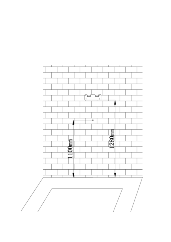
1.1. Installation
Installation must be carried out by personnel with
professional qualification, otherwise there is a risk of
electric shock.
It shall be installed in the place without violent vibration
and impact and placed vertically to facilitate ventilation.
It shall be installed on noncombustible materials such
as metal, or there is a risk of fire.
Do not drop any foreign objects, especially metal
objects, into the inside of the charging station or there
is a risk of fire. The lead nose of the charging station
must be securely attached or there is a risk of damaging
the equipment.
The power supply input cable should have at least
5G2.5mm² (minimum) copper cable while it is
recommended 5G4mm² copper input cable.
1.2. Maintenance
It is recommended that routine safety inspection visits
to charging station be conducted at least once a week.
Please do not attempt to disassemble, repair, or modify
the charger by yourself. If there is a need for
maintenance or modification, please contact certified

3
Electrician/Installers. Improper operation may cause
damage to the equipment.
Do not put inflammable, explosive or combustible
materials, chemicals, combustible steam and other
dangerous goods near the charging station, otherwise
there is a risk of fire.
Please keep the charging adapter clean and dry and
wipe with a clean, dry cloth if soiled. Do not touch the
charging station with your hand when charged.
1.3. Operation
Strictly forbidden for Children or persons of restricted
capacity to approach the charging station to avoid
injury.
Forced charging is strictly forbidden when the electric
vehicle or charging station fails.
Electric vehicle can only be charged with the engine is
off and stationary. Do not charge in rainy and
thunderous weather.
It is strictly prohibited to use the charging station when
the charging adapter or charging cables are defective,
cracked, worn, broken or the charging cables is
exposed. If you find any, please contact the supplier in
time.
In case of rain or thunder, please charge with care.
DO not use the device in extreme temperatures outside
the normal operating range at -30°C to 55°C.

4
Lightning-proof
Flame
resistance
Overvoltage
protection
Waterproof
IP55
Overcurrent
protection
Leakage
protection
Overheat
protection
IEC 62196-2
(Type 2) connector

5
2. Feature
•Compact size design with charging power up-to 11kW.
•Charging plug meet IEC 62196-2 (Type 2) standard.
•Charging adapter is with IP55 waterproof rating for
outdoor usage.
•EV Charger meets IEC 61851 control principle
•Long durability: Charging adapter at no-load plug in/
pull out > 10000 times
•High impact of external force resistance
3. Package Content
•AC EV Charging Station including charging cable x 1pc
•Mounting accessory set including screws x 1set
•Cable management hook x 1pc
•User manual x 1pc

6
4. Technical Specification
Electric
parameters
Charging mode
Mode 3
Input Voltage
3-phase AC, 400V±15%
Rated frequency
50/60Hz
Branch breaker
N/A
Input circuit
conductor
L1/ L2/ L3/ N/ PE
Copper cable is
recommended with
appropriate conductor
size.
Functional
description
Charging control
Direct “Plug-and-
charge”
Display screen
N/A
Indicator lights
LED light indicator
with 3-color (status,
connect, charging and
fault)
Communication
interface
Onboard RS-485
interface
Safety
precautions
Surge protection,
Over temperature
protection,
RCD Type A + DC6mA,
Over/under voltage
protection, over
current protection,
groundprotection

7
Mechanical
parameters
Mounting
Wall-mounted
Charging adapter
IEC 62196-2, Type 2
Charging cable
length
5m
Dimension
(H×W×D)
310mm × 161mm ×
79.8mm
Weight
≤5kg
IP rating
IP55
Environmental
conditions
Operational
environment
Indoor or outdoor,
good ventilation, no
flammable, explosive
gases
Vibration
No violent vibration
and impact
Storage
temperature
-40~75°C
Operating
temperature
-30~55°C
Operating
humidity
95%RH, no water
droplet condensation

8
5. Product Dimension
6. Internal Wiring on AC Terminal Block
AC Input Cable Pin Definition
L3 L2 L1 N PE

9
7. Installation process
1. Position the mounting bracket at the desired height or
following the recommendation below. Install the
bracket onto the wall with the screws packed inside the
package

10
2. Open the back-cover of the Charger and pre-install the
AC input cables following the pin definition on the
Terminal Block.
AC Input Cable Pin Definition
L3 L2 L1 N PE

11
3. Mount the EV Charger onto the wall by hanging it on the
installed bracket. Install another screw from the front to
lock it.

12
4. It is recommended to install the Charging adapter hook
onto the wall at an installation height of 800mm from
the ground

13
5. To complete the installation with an external circuit
breaker at the input side.

14
8. Power-on inspection
8.1. Check before operation
Before operation, please check carefully and ensure the
following:
•The installation position of the EV Charger is convenient
for operation and maintenance
•The EV Charger and its accessories are correctly
connected and installed firmly
•Reasonable selection of leakage protection switch for AC
inlet
•No external objects or parts are left on the top or inside
the Charging Station
8.2. Power on the device
1. Switch on the AC power inlet leakage protection circuit
breaker
2. Power on the Charger: It would take 5 seconds initially
for power-on self-check.
3. After the power-on self-check is completed, the LED
indicator would show the status:
a. Normal standby:
the green light is always (constant) ON.
b. Equipment failure:
Red light is always (constant) ON.
4. When the EV Charger is showing GREEN light constant
ON, then you can take out the Charging adapter to start
charge your Electric Vehicles.

15
5. If your EV Charger is showing RED color, please check
below LED status for error code or contact the
manufacturer
8.3. Start charging
1. Park the electric car into place, turn off the engine, and
put the car under braking.
2. Pick up the charging adapter from the Charger after
Charger is showing Green light constant ON after power-
on self-test.
3. Plug the charging adapter into the AC charging socket of
the electric vehicle and you will see Blue light flashes
indicating charging in progress.
4. As this is direct “plug-and-charge” charging station, it
will automatically enter the charging process.
8.4. Normal stop charging
1. There are two ways to stop charging:
a. Automatic stop when fully charged.
b. Manually stop by removing the charging adapter
from the car socket.
2. Pull the charging adapter out from the vehicle to
complete charging process. If you can't pull out the
adapter, usually because the vehicle is locked, press the
unlock button of the vehicle key and the adapter can be
pulled out.

16
8.5. Abnormally stop charging
1. Forced fault stop: A fault stop initiated by the onboard
charger of vehicle.
2. Automatic fault stop: A fault stop initiated by the
charging station due to internal protection mechanisms
9. LED indicator for Status and Error codes
Index
Description
LED Color Indicator
Definition
Green Blue Red
1 Initial
Power-on ON Off Off
Ready to be used
after 5 seconds of
Power-On
Initialization.
When LED is
Green, it is ready
to be used.
2
Connecting
(hand-
shaking
with EV)
Flashes
Off
Off
After self-test, the
device is READY to
plug into Electric
Carsocket. During
connection, there
is a handshaking
process with EV
which the Green
LED will flashes
quickly.

17
3 Charging
starts Off Flashes
Off
During charging,
the Blue light
flashes as charging
inprogress
4 Charging
finishes Off On Off
When charging
finishes, the Blue
light will be
constant ON
5
Control
Pilot
Pin Error
Off Off
Fault
(0.5s)
1 time
When Control
Pilot pin detects
error during
handshaking
with Electric
vehicle
6 Under
Voltage Off Off
Fault
(0.5s)
2 time
Error detected:
when Voltage
< 304Vac
7 Over
Voltage Off Off
Fault
(0.5s)
3 time
Error detected:
When Voltage
> 456Vac

18
8
Leakage
Detected
Off
Off
Fault
(0.5s)
4 time
When RCD detects
leakage, the relay
automatically
disconnected the
system. It needs to
be re-powered
after the fault is
removed before
the relay is allowed
to close to function
again
9
Over
Current
Off
Off
Fault
(0.5s)
5 time
When over current
is detected, the
relay is
disconnectedthen
it will
automatically
restart after 10s.
When over
current is
detected,
the charging would
be ended.
10
Over
Temp
Off
Off
Fault
(0.5s)
6 time
Temperature >85
degrees, it will
disconnect the
relayautomatically.
Wait for the device
to cool down
before turning on
the EV
Charger again

19
11
RCD leakage
detection
self-check
Off Off
Fault
(0.5s)
7 time
When wall-box is
powered-on each
time, it will trigger
a self-check for
RCD leakage
detection. If RCD is
not working, it will
flash red color LED
7x times.
12 Emergency
Stop button Off Off
Fault
(0.5s)
8 time
When the
emergency stop
button is pressed
on the side of the
wall-box, it will
flash 8x times red
LED to indicate this
situation. Please
release the
Emergency Stop
button after all
fault is removed to
return back to
normal state.

20
Hereby Assmann Electronic GmbH, declares that the
Declaration of Conformity is part of the shipping content. If
the Declaration of Conformity is missing, you can request it
by post under the below mentioned manufacturer address.
www.assmann.com
Assmann Electronic GmbH
Auf dem Schüffel 3
,
58513 Lüdenscheid
Germany
Table of contents
Other Digitus Batteries Charger manuals

Digitus
Digitus DA-10083 User manual

Digitus
Digitus DA-11005 User manual

Digitus
Digitus DA-10071 User manual

Digitus
Digitus DA-10084 User manual

Digitus
Digitus DA-10080 User manual

Digitus
Digitus DN-45003 User manual

Digitus
Digitus DA-10193 User manual

Digitus
Digitus DA-10081 User manual

Digitus
Digitus DA-10061 User manual

Digitus
Digitus DA-10194 User manual