Digiway SL500 User manual

1
SL500 Sliding Gate Motor Rack Drive
SL500 Sliding Gate Motor Chain Drive
Version –V2.0
INSTRUCTION MANUAL

2
ATTENTION To prevent electrical shock, disconnect from power source before installing or service
ATTENTION Electricity and power motors associated accessories could be fatal or at least cause seriously
injury. All main voltage wiring must be installed by a licensed electrician.
ATTENTION Additional safety device MUST be fitted such as Photo Electric Beam, Loop Detectors.
ATTENTION Before do the manual release, the mains power switch must be off even there is no power.
ATTENTION Before power on, the manual release MUST engaged
ATTENTION Gate opened stopper and closed gate stopper MUST be installed.
Contains
1. General layout --------------------------------------------------------------------------------------------------3
2. Specifications ---------------------------------------------------------------------------------------------------4
3. Control Board layout -------------------------------------------------------------------------------------------4
4. Control Board input---------------------------------------------------------------------------------------------5
5. DIP switch function --------------------------------------------------------------------------------------------5
6. Motor Set up ----------------------------------------------------------------------------------------------------5
7. Chain drive ------------------------------------------------------------------------------------------------------6
8. Power Supply and drive type --------------------------------------------------------------------------------- 6
9. Manual release---------------------------------------------------------------------------------------------------7
10. Trouble shooting guide----------------------------------------------------------------------------------------8
11. Condition of sales----------------------------------------------------------------------------------------------9

3
1) Motor Cabinet
2) Limit Switch
3) Steel base
4) Chain drive guide roller
5) 12V motor
6) Manual release
Limit Rack Drive Limit Chain Drive
Encoder Rack Drive Encoder Chain drive
GENERA LAYOUT

4
1. General Descriptions
The SL500 sliding gate motors was designed for domestic sliding gate or swing gate, rack drive or chain
drive, limit switch or encoder control. The controller can receive the signals from swipe card, loop
detectors, remote control, photo-electric beams and any kind of access control system. Metal zinc plated
base.
2. Technical Specifications
Power supply
230/240V AC, low voltage, solar panel
Output voltage
12V
Motor rate
12V DC 100W geared motor
Gate type
track, cantilever gate, rack or chain drive
Drive speed
Up to 200mm/sec
Max. Gate length
10M
Fully programmable
Auto close time
Access control
Remote, Keypad, Switch, Push Button etc.
3. Control Board layout
CONTROL INPUIT AND BUTTON
Control input LEDs
Encoder plug
Control
terminals
block
12V or 24V charger select
Terminals block
OSC Button
Motor obstruction force
PE Bypass
Receiver
board
Learn Button
DIP switch
Input select

5
4. Control Board Input
OSC input
The OSC inputs terminal input can be from switch, push button or relay (from any other brand
standalone receiver) N/O. It became active when short to COM. This terminal can be set to OSC or
OPN function by jumper on board. If keep active, gate will stay open.
PEB input
If the P.E input activated while gate is closing, the gate will stop or reopen. If the gate in the opened
position and P.E beam activated, the gate will stay in opened.
CLS limit input
If gate is closing cycle, when CLS limit is active, gate will stop and controller will display closed. If
controller working encode model, this terminal no function
OPEN limit input
If gate is opening cycle, when OPN limit is active, gate will stop and controller will display opened.
If controller working encode model, this terminal no function
OSC button
The OSC button operate gate (Push Open, push again Stop, push again Close) and set auto close time.
Encoder inputs
Encoder is mounted on the motor shaft inside of motor. it is not serviceable by customer. There are two
four pings socket on control board, one for right hand gate and other one for left hand gate.
5. DIP SWICTH FUNCTION
DIP1 –SET/RUN ON=SET, OFF=RUN
DIP2 –ENCODER/LIMIT ON=ENCODER OFF=LIMIT
DIP3 –POWER SELECT ON= 80% OFF= 100%
DIP4 -- AUTO CLS ON=AUTO CLS OFF=NO AUTO CLS
6. Motor Set up
6.1 Encoder control --- DIP2=ON
Motor installation as other motor and do not mention here.
Default setting is gate closing to left. If gate close to right, you need swap two motor wires and move
the encoder plug to J1. Make sure gate has opened and closed stopper installed, then power up, push
OSC button or remote, after two completely operation cycle, controller will be automatically
programmed. Do not need do anything.
6.2 Limit control --- DIP2=OFF
Default setting is gate close to left. If gate close to right, you need swap two motor wires and swap
close and open limit switch input. Push OSC button or remote, after two completely operation cycle,
controller will be automatically programmed. Do not need do anything.
6.3 Timers setting
Auto close time set
Set DISP1 On, push and hold on OSC, the time you push and hold OSC button is the time of
gate auto close time. when reached the required time simply release OSC button. Set DIP1
CONTROL INPUIT AND BUTTON

6
OFF. The gate controller will back to working mode. Factory default auto close time is 30
seconds
To restore factory setting, turn power off and set DIP1 on, push and hold CLS button then power
on. While hold CLS button, set DIP1 off, release the CLS button. Now controller restored factory
setting from memory.
7. Chain dirve Systme Setup
This is the drawing for chain drive setup. Not need to mention the details and all those are quite simple
mechncial work.
8. Power Supply and drive type
This motor has three different power can be choose. 240V, Low voalteg and Solar.
If has 240V power near at the gate, then use 240V version SL500 eithe encoder or limit control.
If no 240V power at gate, but has 240V power in the gararge or house, then choose SL500LV low
volatge model. Run12V low volatge to the gate. Suggest use 2.5mm garden light cables either direclty
bury in the ground or in conduit.
If no 240V power at ht egate and nearby, then use solar. 20W or 40W 12V solar panel and 12V7Ah
battery is good enough for normal use. If gate is more feqencly used and the sun light is not very good,
then properly inceasing solar panel power and battery size.

7
9. Manual release
A: What to do during a power failure (battery run out) or faulty:
If got battery back, then take the red cap off or take whole cover off, using the 8mm Allen key, insert to
the release bolts holes or use hand, clockwise turn the bolts several turns, then can manually push gate
open.
Re-engage the motor, turn the manually release bolts several turns, manually move gate, gate will
engage.
Reset power (initialization), remove the 6 pins plug (AC power, battery and motor), wait about 20
seconds, then plug it back. Use remote or push button operate the gate, controller will automatic
reprogrammed.

8
10. Trouble Shooting Guide
10.1 Display information on main control board.
Between Pot and OSC button on the control board, there are two LEDs --- GREEN and RED. Different
combination and show different gate situations.
(1) Gate status LED
Gate Status (Position) \ LEDs
Status LED-Green
Status LED-Red
Gate in closed position
Slow Flash
on
Gate is opening
Fast flash
off
Gate in opened position
on
Slow flash
Gate is closing
off
Fast flash
Gate stop in the middle
Alternatively, flash
Alternatively, flash
Gate stop in the middle: which means the gate stop by OSC input and at this position the auto close
does not apply.
(2) Input LEDs
Inputs LEDs\ Input status
Input Active
Input inactive
OSC LED--- OSC input
on
off
PEB LED --- Photo Electric Beam-
on
off
Open Limit LED
off
on
Close Limit LED
off
on
10.2 Trouble Shooting Guide
Malfunction
Possible causes
What to do
Gate not open
1) No power
2) Already in opened
position
1) Check the power
2) Reset the power, remove 6 pins plug and
wait 20 seconds, and plug it back
Gate not close
1) Safety input PEB active,
PEB LED is on
2) OSC input active, OSC
LED is on
1) Check the safety device, N/C contact
required.
2) Check control switch button in case it is
on
Gate run little bit
then stop and both
Status LEDs flash
1) No encoder input
2) mechanical jammed
1) encoder plug wrong or faulty
2) power off and disengage the motor and
push and pull the gate manually
Gate opened or
closed position not
right
1) encoder or limit wrong
2) Rack jumps over drive
pinion
1) Reset the power, remove 6 pins plug and
wait 20 seconds, and plug it back
TROUBLE SHOOTING GUIDE

9
1. Orders
The placement of any orders upon Digiway implies acceptance of these terms and
conditions and takes precedence over any other terms and conditions written or oral.
2. Deliveries
(a) Time of delivery will be complied with wherever possible. It is not guaranteed and
is subject to extensions to cover delays caused by strikes, vehicle breakdown, traffic
delays, weather and any causes beyond Digiway’s control.
(b) The Purchaser shall not be entitled to be compensated for any loss or damage due
to any of the causes stated.
(c) Most of the motors are stock items, but temporarily runs out of stock. Restock
time can experience of approximately 8-12 weeks from receipt of official written
order.
3. Warranty
(a) Digiway has 12 months return base warrants from date of purchase in normal use
condition.
(b) Digiway control boards can be up to two years warranty. subject the application
conditions.
(c) In lieu of all other warranties expressed or implied. Digiway shall not be liable for
any special indirect, incidental or consequent damages of any kind or nature.
Equipment manufactured and installed by it to be free from defects in material and
workmanship for. Digiway will repair or replace at its option any product or part
which it determines to contain defective material and workmanship. Defective parts
must be returned to Digiway for repair or replacement. Costs associated with the
return of the goods will be the responsibility of the sender. On site repairs will incur
travel and labor charges. Liability for replacement parts or repairs carried out by
Digiway does not extend the original twelve-month warranty period.
4. Payment
(a) Unless agreed expressly in writing, otherwise the terms of payment shall be made
prior to shipment or where agreed on completion of the installation. Methods of
payment are by:
(i) Direct bank transfer with remittance advice supplied from purchaser.
(ii) Cheque’s need to be received and cleared before shipment.
5. Returns
Returns only accepted within 14 days of invoice. Credits only paid after inspection of
goods. All returns subject to 30% re-stocking fee on product. Damaged goods are
subject to further charges to the value of the damage.
CONDITION OF SALE
This manual suits for next models
2
Table of contents
Other Digiway Door Opening System manuals
Popular Door Opening System manuals by other brands

B&S
B&S Smart Pro SDO-9V3 installation instructions

Record
Record 102-020.110.805 Maintenance and troubleshooting
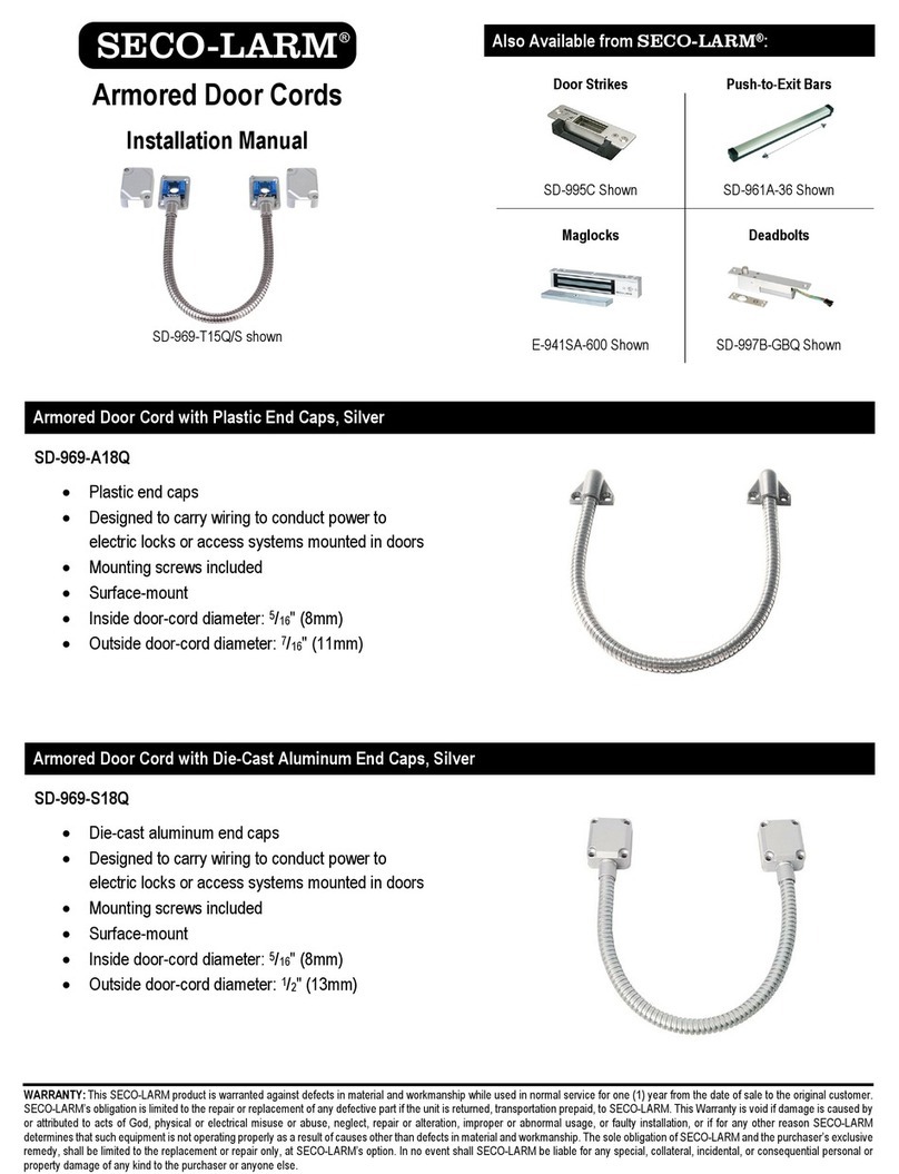
SECO-LARM
SECO-LARM SD-969-A18Q installation manual

LCN
LCN 4840 installation instructions
Assa Abloy
Assa Abloy Corbin Russwin ED4000 Series installation instructions
Assa Abloy
Assa Abloy RD3 user manual
GEZE
GEZE Slimdrive SL NT Installation and service instructions
Manaras
Manaras Opera-MH Installation instructions manual
Assa Abloy
Assa Abloy Norton 9540 Series installation instructions
BFT
BFT ELI-250 Installation and user manual

Dormakaba
Dormakaba UNIVERSAL PT 60 Mounting instructions
AGS
AGS TST40 Assembly instructions
