TOPP K200 User manual
INSTRUCTIONS FOR INSTALLATION AND USE
K200
AUTOMATION AND ELECTROMECHANICAL DRIVERS
FOR LINEAR SLIDING DOORS WITH ONE OR TWO PANELS
COD. 0P5506
EN
VER 0.0
REV 08.19
installer's manual/original instructions


EN
INDEX
3
INSTRUCTIONS FOR INSTALLATION AND USE
EN
EN
K200
5.7- List of errors and warning ................................................................................................................pag. 47
5.8- Self restore management of errors C-D-E-K-N-P-Q ........................................................................pag. 48
5.10- Self restore management after anti panic alarm ..................................................................pag. 49
5.11- self restore management after ........................pag. 49 opening fire or an opening of emergency
6- APPENDICES
6.2- Spare parts and optional accessories ..............................................................................................pag. 51
5.12- Digital switch .................................................................................................................................pag. 50
6.1- Maintenance.....................................................................................................................................pag. 51
6.3- Disposal ...........................................................................................................................................pag. 52
5.9- Self restore management of errors F-G-H-I-J .........................................................................pag. 49
6.4- Troubleshooting................................................................................................................................pag. 52
7- EC DECLARATION OF INCORPORATION OF PARTLY COMPLETED MACHINERY ..........................pag. 53
EU DECLARATION OF CONFORMITY....................................................................................................pag. 53
1.3- Installer.............................................................................................................................................pag. 04
3.8- Installing the door block ...................................................................................................................pag. 20
1.5- Servicing...........................................................................................................................................pag. 05
2- TECHNICAL DESCRIPTION
2.5- Models..............................................................................................................................................pag. 07
2.3- Technical data .................................................................................................................................pag. 06
3.1- General recommendations...............................................................................................................pag. 11
3.2- Installing the crossbar ......................................................................................................................pag. 11
2.2- Proper use .......................................................................................................................................pag. 05
1.1- General recommendations...............................................................................................................pag. 04
3- INSTALLATION
1.2- General safety rules ........................................................................................................................pag. 04
2.4- Packing ............................................................................................................................................pag. 06
1.4- User..................................................................................................................................................pag. 05
2.6- Sliding doors with one panel ...........................................................................................................pag. 08
3.4- Installing the carriages on the door..................................................................................................pag. 13
1- GENERAL INFORMATION
2.1- Rating place and “CE” marking .......................................................................................................pag. 05
3.3- Installing the adapter and track........................................................................................................pag. 12
2.7- Description of parts and dimensions ...............................................................................................pag. 09
3.5- Fastening and adjustment of the sliding panels...............................................................................pag. 14
3.7- Fastening the drive brackets on the door panel...............................................................................pag. 18
3.9- Installing the casing .........................................................................................................................pag. 21
4- ELECTRICAL CONNECTION
3.6- Installing the motor module, belt transmission, belt,logline..............................................................pag. 16
4.1- General recommendations...............................................................................................................pag. 22
4.4- Pre-wired electrical connections ......................................................................................................pag. 24
4.8- DS2 digital connection .....................................................................................................................pag. 41
4.9- Connection of key device.................................................................................................................pag. 42
4.2- Electrical connection ........................................................................................................................pag. 22
4.5- Electrical wiring diagram (flow chart) ...............................................................................................pag. 25
4.3- Electronic circuit board.....................................................................................................................pag. 23
4.6- Connection of detection sensors .....................................................................................................pag. 26
4.7- Program selection with MS1 knob ...................................................................................................pag. 41
4.10-Antipanic connection.......................................................................................................................pag. 42
4.11- Connetion of door block and pharmacy function ...........................................................................pag. 43
5- USE AND OPERATION
5.1- Technical description .......................................................................................................................pag. 44
5.3- First card start-up ............................................................................................................................pag. 44
5.4- Reset phase: learning .....................................................................................................................pag. 45
5.5- restart in case of power failure:zero (near).......................................................................................pag. 45
5.6- Programming parameters ...............................................................................................................pag. 46
5.2- Emergency battery ..........................................................................................................................pag. 44

IT
GENERAL INFORMATION
1
Before installing the automation the installer must read and understand all parts of this manual.
&TOPP srl reserves the right to amend or improve the manual and the products described therein at any time without
notice.
&This manual is an integral part of the automation unit and must be kept by the installer, with all the enclosed
documentation, for future reference.
&This manual was written by TOPP srl, which holds the copyright. No part of this manual may be reproduced or
published without the manufacturer's written authorization.
&This manual provides all instructions necessary to ensure correct installation and maintenance of the automation:
TOPP srl is not liable for any damage to persons, animals and property caused by failure to follow these instructions.
&The data contained in this manual were written and checked with the maximum care; TOPP srl is not liable for possible
errors due to omissions or printing errors, or errors in transcription.
1.1
GENERAL RECOMMENDATIONS
&The installer must verify compliance with the current directives and regulations on the safe use of motorized doors.
&Installation of the automation must be done exclusively by qualified technical personnel in possession of the
professional requisites foreseen by the laws in the country of installation.
&Every installer must provide visible annotation of the data identifying the drive system.
&The installer must be able to install the automation, start it and operate it with the power on in electrical cabinets or
shunt boxes, and must be qualified to perform all actions of an electrical and mechanical nature and any kind of
adjustment.
&After installing the automation, the installer must analyze the system for risks and verify that the sliding door
installation does not present risks of crushing or shearing, adopting adequate corrective measures, if necessary, and
applying the warning signs foreseen by the laws in force to identify hazardous zones.
4
1.3
INSTALLER
1.2
GENERAL SAFETY RULES
&IMPORTANT! – During handling and installation of the parts, the personnel shall be equipped with suitable personal
protection equipment (PPE) so as to perform the works required under safe conditions.
&IMPORTANT! – The personnel must be informed of the risks of accident, about the safety devices for the operators
and about the general rules for accident prevention foreseen by the international directives and laws in force in the country
in which the automation is installed. In any case, the personnel must comply scrupulously with the safety regulations for
prevention of accidents in force in the country in which the automation is installed.
&IMPORTANT! – To prevent injury and risks for the health of the workers, the maximum limits shall be applied for
manual handling of loads, as provided in standard ISO 11228-1.
&When handling electric parts always wear grounded antistatic conductive bracelets as electrostatic charges can
damage the electronic parts on the circuits.
&Any tampering with or unauthorized replacement of parts or components of the automation mechanisms and any use
of accessories or consumables other than the originals may represent a hazard and relieves the manufacturer of any civil
and penal liability.
& In order for the automation unit to operate correctly, shall be carried out periodical maintenance on it, as indicated in
par. 6.1 of this manual. Maintenance operations that require the automation unit to be even partially disassembled should
be carried out exclusively after the power supply to the same has been cut off.
&Never try to oppose the movement of the door and work near the hinges or other mechanical moving parts in motion
(such as belts, carriages, etc.). The manufacturer is not liable for any damages caused by improper or unreasonable use
of the automation.
&Children must not play with the device.
&The automation contains mobile mechanical parts, electrical connections and electronic circuits for control of door
movement; the automation must therefore be protected, along its entire length, by an aluminum casing.
&This device may be used by children no younger than 8 years of age, by people with reduced physical, sensory or
mental capacities and by inexperienced users, as long as they are supervised or as long as they have received
instructions on the safe use of the device.
&Do not remove or alter the plates and labels applied by the manufacturer on the automation and its accessories.
INSTRUCTIONS FOR INSTALLATION AND USE
EN K200

5
Contact the installation technician or retailer for assistance.
1.5
SERVICING
IT
TECHNICAL DESCRIPTION
2
2.1
RATING PLATE AND “CE” MARKING
It is formed of an adhesive plate made from polyester, screen-printed black, with the following dimensions: W=50mm -
H=36mm.
It should be applied by the installation technician in a clearly visible position on the outside of the automation unit.
The “CE” marking certifies the conformity of the machine to the essential health and safety requisites foreseen by the
European product directives.
1.4
USER
Use of the automation must be exclusively permitted to users who comply with the instructions in this manual and in the
manuals of the TOPP devices connected to it.
The user must not open the casing or perform any operations restricted to maintenance personnel or specialized experts.
In case of breakdown or malfunction of the door, the user should simply switch off the circuit breaker and abstain from any
attempt to repair the system.
The user must be able to operate the automation under normal conditions and perform simple operations or startup or
resetting the automation following any forced interruptions, using the devices provided (digital switch, analogue switch,
etc.).
INSTRUCTIONS FOR INSTALLATION AND USE
EN
K200
&The installation technician shall accept full responsibility for any installation errors and for any failure to adhere to the
instructions provided in this manual. The installation technician shall therefore be exclusively liable for any damages
caused to users and/or third parties that may arise as a result of incorrect installation.
&The installer must also supply the owner with all information regarding automatic, manual and emergency function of
the automation.
2.2
PROPER USE
In case you want to exclude the auto recovery please contact support Topp Srl.
The K200 automation mechanism was designed and produced exclusively to operate (open and close) linear sliding
doors in residential, public and industrial buildings.
The recovery action must be taken into account in applications where there are features that provide access
control with inputs different from those of the radar (example reader bedge) for which automation could not
ensure the operating mode set.
The door may be used in escape routes only if equipped with anti-panic break-through systems. It must be possible to
break through in the direction of escape no matter what the position of the door.
The automation software is designed to perform automatic recovery in the instance where anomalous
The automation in order to perform the above, if set in a mode other than "Closed", perform a reset called "Near"
that provides for the complete opening and closing of the doors at a low speed, before returning in the set state the
function selector.
events as described in chapters 5.8-5.10.
It is strictly forbidden to use the automation for purposes other than those described herein, in order to guarantee at all
times the safety of the installer and user and the correct function of the automation.

6
2.4
PACKING
%N.1 K200 automatic door (complete with motor unit and belt transmission preassembled on the crossbar, side caps,
casing, door stop limit switch, cable raceway, emergency battery,raceway,rubber cable sleeves);
%N. 2 warning labels for moving wings that have to be sticked on the centre of the moving wings (refer to picture A);
%N.2 Supporting brackets on the crossbar;
The number of some of the parts described above may vary depending on the type of configuration (e.g. number of door
panels). If more parts are necessary, contact the manufacturer.
Make sure the parts described above are in the package and that the automation has not undergone any damage in
shipment. If you find anything unusual, do not install the automation and request the service department of the local
retailer or the manufacturer.
%N.1 package of hardware consisting of 2 self-tapping screws TC d6x70 and 2 nylon anchor bolts 10x60;
%N.1 Adapter for framed door panels;
%N.2 Carriage units with relative hardware for fastening to the adapter;
Every standard product package (cardboard carton) contains:
2.3
TECHNICAL DATA
Tab. 1 lists the technical data that characterize the K200 automation.
POWER SUPPLY
PROTECTION OF ELECTRIC DEVICES
WORKING TEMPERATURE
NUMBER OF DOOR PANELS
230V ~ 50Hz
24V 500mA max
0,41A
90W
Continuous
Adjustable 10 ÷ 80 cm/s
Adjustable 1 ÷ 5 cm/s
Adjustable 0 ÷ 60 s
IP X0
1 PANEL 2 PANELS
K200
MODEL
Tab. 1
PERIPHERAL POWER OUTPUT
POWER ABSORBED
ABSORPTION
OPENING/CLOSING SPEED
OPENING/CLOSING APPROACH SPEED
AUTOMATIC CLOSING TIME
TYPE OF USE
MAINS VOLTAGE FUSE 230V
OPENING/CLOSING ACCELERATION Adjustable 1 ÷ 12
5 x 20 - T800 delayed
MAXIMUM CAPACITY
SIZE OF OPENING
140 kg
800÷2800 mm
100 + 100 kg
1000÷2800 mm
INSTRUCTIONS FOR INSTALLATION AND USE
EN K200
-20°C
+50°C
Warning labels
for moving wings
Ref. A
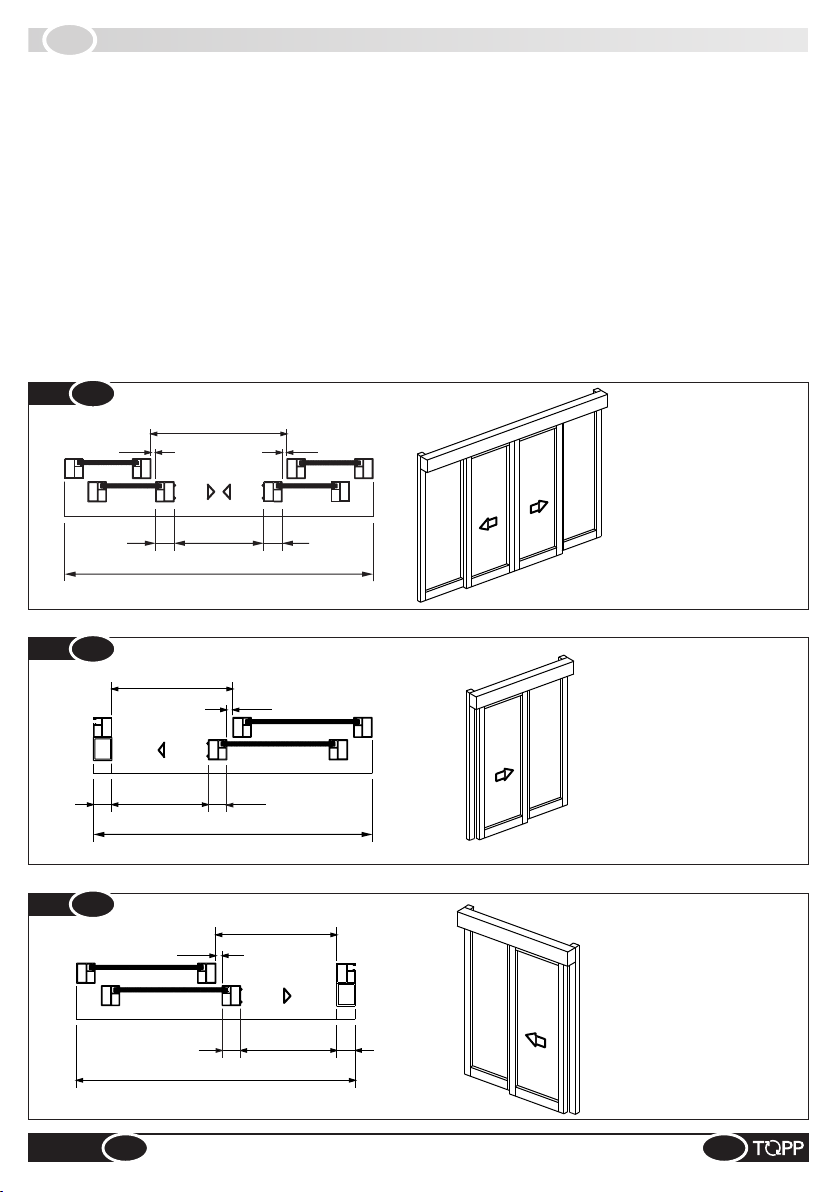
2.5
MODELS
Two models of automation are available:
@When order a single door panel application, always specify the direction of opening of the door, seen from the front
of the automation.
%automation with 2 door panels (Fig.2) which allows a pair of door panels to glide simultaneously in opposite
directions;
%automation with 1 door panels which allows a single door panel to glide in one direction; Fig.3 shows an application
with a single door that opens toward the right (seen from the front of the automation); Fig.4, shows a single door that
opens toward the left (seen from the front of the automation).
@To comply with the safety regulations, the glide of the door panel VPA must be less than the door opening width VL.
The glide of the door panel VPA is equal to VL when the upright on the door does not have any roundings and/or
protrusions that could cause a shearing effect.
VPA*
VL
LT/LC
25 25
75
75
VPA*
VL
LT/LC
25
75
75
VPA*
LT/LC
25
75 75
LT/LC
LT/LC
PC
BP
PC
BP
PC
PC
LT/LC
LT/LC
PC
BP
BP
PC
Fig. 2
Fig. 3
Fig. 4
7
VPA = net doorway width
LT/LC = automation length /
casing length
VL = gross opening
BP = rail + runner on the floor
PC = electric wire raceway
1 RIGHT DOOR PANEL
1 LEFT DOOR PANEL
2 DOOR PANELS
VPA = net doorway width
PC = electric wire raceway
LT/LC = automation length /
casing length
BP = rail + runner on the floor
VL = gross opening
BP = rail + runner on the floor
VPA = net doorway width
LT/LC = automation length /
casing length
VL = gross opening
PC = electric wire raceway
INSTRUCTIONS FOR INSTALLATION AND USE
EN
K200
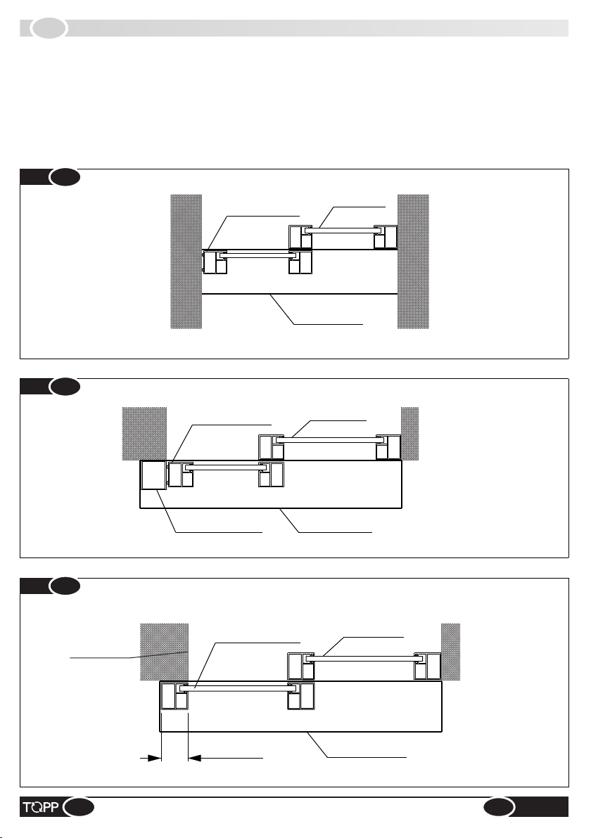
2.6
DESCRIPTION OF PARTS AND DIMENSIONS
To reduce the hazard of getting the fingers caught, we recommend the assembly type as shown in Fig.5a and Fig.5b,
where the wall and/or tubular frame act as a jamb and stop the door panel.
@In some countries the laws forbid this type of assembly as there is a possible risk of getting the fingers caught.
Alternatively, proceed as shown in Fig.6 overlapping the end of the wall (and/or closing upright) with the profile of the
sliding panel and moderating the closing speed and speed of approach of the door.
Fixed door
panel
Sliding door panel
Automation
Fixed door panel
Sliding door panel
Tubular jamb Automation
Fixed door panel
Sliding door panel
Overlap Automation
Fig. 5a
Fig. 5b
Fig. 6
8
Wall end
INSTRUCTIONS FOR INSTALLATION AND USE
EN K200

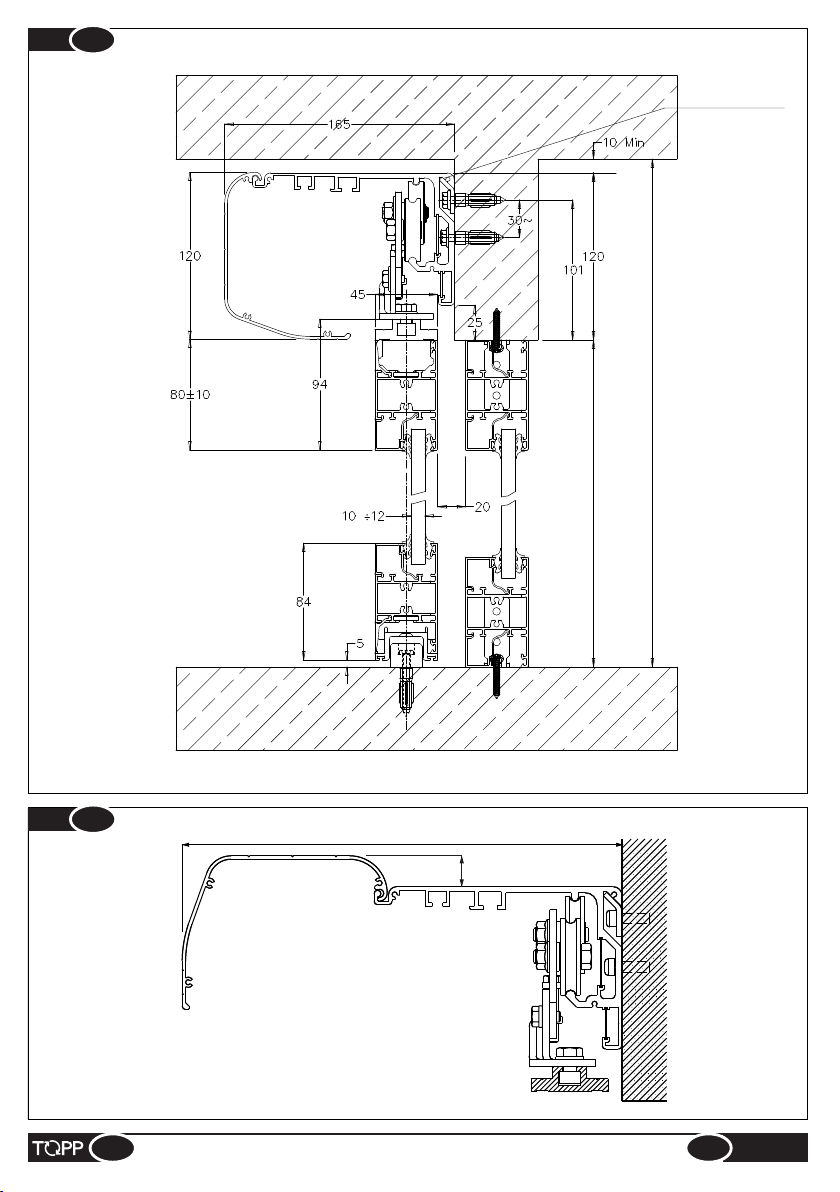
2.7
DESCRIPTION OF PARTS AND DIMENSIONS
1 -
2 -
3 -
4 -
5 -
6 -
7 -
Main crossbar
Carriage with double wheel
Adapter for door panel suspension
Casing
Toothed transmission belt
18 - Door stop
11 - Door lock with manual release
12 -
13 - Photocell control unit
14 -
15 - Rail for door guide
16 - Plastic runner on floor
17 - Wire raceway
8 -
9 -
10 -
Door panel drive bracket
Belt transmission with pulley
Low voltage transformer
Electronic control circuit
Lateral case fastener
Emergency battery
Gearmotor
Metal motor module19 -
Crossbar supporting hooks
9
INSTRUCTIONS FOR INSTALLATION AND USE
5
Fig. 7
20 - Logline
EN
K200
15 15
16 16
13
44
9
67
63
19
3
218
18 12 11
10
14
1
20
17
17
7
8
255
20
Fig. 9
10
INSTRUCTIONS FOR INSTALLATION AND USE
EN K200
Ceiling height
Opening door height
Crossbar supporting
bracket
Fig. 8

IT
INSTALLATION
3
3.1
GENERAL RECOMMENDATIONS
The automation must be installed exclusively by competent, qualified technical personnel in possession of the
technical requisites foreseen by the legislation in force in the country of installation.
&Do not install the automation on the external wall of the building, subject to atmospheric agents (rain, snow, etc.).
&Do not use the automation in environments with a potentially explosive atmosphere.
&During installation of the door, take care to avoid any risks during the movement of closure and/or opening the door,
and to protect against risks in accordance with the provisions of standard EN 16005 at item 4.6.21 for the door opening
movement and item 4.6.2.2 for door closure. Protection of the primary closing edge should take account of the types of
users of the door (see EN 16005, 4.6.2.2).
&The forces developed by the complete system during operation must respect the regulations in force in the country of
installation; if this is not possible, protect and signal by means of electronic safety devices the zones affected by those
forces.
&Before installing the automation, verify that the structure to be automated is stable, sturdy and able to withstand the
weight of the automation and, if necessary, take steps to ensure that it is. Topp Srl is not liable for failure to comply with the
rules of good workmanship in the construction of the door panels to motorize, or for any distortions that may develop with
use of the device.
&The glass for door panels shall comply with the provisions of the Standard (EN 16005 4.4.2 - Materials: tempered
glass in accordance with EN 12150_1; stratified glass in accordance with EN ISO 12543-1 and EN ISO 12543-2).
(Model with two panels) To install the crossbar, proceed as follows:
%Mark the surface where the automation will be fastened at the center of the opening VL that is also the center of the
crossbar;
@If the floor is not perfectly flat, decide the position of the supporting brackets referring to the highest point of the floor.
%Fasten the crossbar supporting brackets to the wall using self-drilling/sell-tapping screws type d5.5 or d6,3;
%Remove the cover on the casing;
%Fasten the crossbar to the wall with 3 self-tapping screws type d6.3 for every meter of crossbar and paying careful
attention not to damage the gliding base of the carriages with the drill spindle. In case of damage it will be necessary to
replace the entire crossbar;
%Install the crossbar and make sure it is aligned;
%After fastening the crossbar clean the glide zone soiled by drilling residues.
%Decide the position of fastening the crossbar supporting brackets, referring to the measurements shown in Fig.8;
3.2
INSTALLING THE CROSSBAR
Ÿto the line of the wall end on the left of the doorway for application of 1 door panel with the opening toward the left;
%Fasten the crossbar to the wall with 3 self-tapping screws type d6.3 for every meter of crossbar and paying careful
attention not to damage the gliding base of the carriages with the drill spindle. In case of damage it will be necessary to
replace the entire crossbar.
%Mark the surface where the automation will be fastened at the center of the crossbar that corresponds:
Ÿto the line of the wall end on the left of the doorway for application of 1 door panel with the opening toward the right;
%Decide the position of fastening the crossbar supporting brackets, referring to the measurements shown in Fig.8;
((Model with 1 panel) To install the crossbar, proceed as follows:
@If the floor is not perfectly flat, decide the position of the supporting brackets referring to the highest point of the floor.
%Remove the cover on the casing;
%Fasten the crossbar supporting brackets to the wall using self-drilling/sell-tapping screws type d5.5 or d6,3.
%Install the crossbar and make sure it is aligned;
%After fastening the crossbar clean the glide zone soiled by drilling residues.
11
INSTRUCTIONS FOR INSTALLATION AND USE
EN
K200

3.3
INSTALLING THE ADAPTER AND RAIL
70÷80 40
Door panel
40
45 Adapter
%Make sure the upper part of the panel crossbar is reinforced at the base (minimum thickness 3 mm);
%Mark the fastening points on the door using the adapter and rail as a templat;
%Drill the door panel at the top and fasten the adapter using cylindrical M6 screws or cylindrical self-tapping d5.5 screws
depending on the type of material;
%Cut the adapter and rail to the measurement of the finished door width, removing another 2 mm from the jamb sider;
@The number of fastening holes will depend on the size and weight of the door.
%Drill the door at the bottom and fasten the rail using flared self-tapping cylindrical screws diam. 4.8.
%Drill the adapter and rail starting at about 70/80 mm from the end;
20
31
Rail
Fig. 10
12
IRON 2 mm (with lesser thickness use threaded rivets)
3 mm (with lesser thickness use threaded rivets)
100 mm
50 mm
Minimum thickness
Materials of the fastening surface
ALUMINUM
SOLID WOOD
REINFORCED CONCRETE
110 mm (with lesser thickness use chemical bolts)
PERFORATED CONCRETE
INSTRUCTIONS FOR INSTALLATION AND USE
EN K200

@Make sure the carriages are installed correctly and are aligned with each other, with the adapter and with the
crossbar.
Install the carriages on the adapter as shown in the figure.
Standard adapter
Fastening nut
Carriage
70 70
7070
15÷70
70 70
15÷70
3.4
INSTALLING THE CARRIAGESON THE DOOR
Fig. 11
Installation by insertion
Fig. 12
Single door panel, opening toward the left
Single door panel, opening toward the right
Fig. 13
Double door panel, simultaneous opening toward the right and left
13
INSTRUCTIONS FOR INSTALLATION AND USE
EN
K200
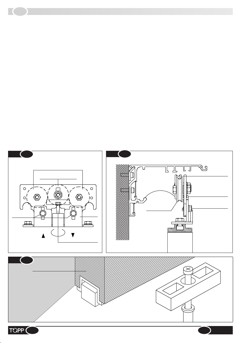
3.5
FASTENING AND ADJUSTMENT OF THE SLIDING PANELS
%Fasten the runner to the floor at point “A” using the anchor bolt and self-tapping screw d 6x70 contained in the hardware
package (Fig.16).
%Before tightening the screws make sure the carriages are aligned with each other and with the crossbar.
To fasten the sliding panels to the crossbar, proceed as follows:
%Loosen the fastening screws on the carriages and insert the no. 10 fixed wrench in the height adjustment screw on the
carriage and turn it to the left or right so that the door panel is about 5 mm off the floor (height for the standard runner);
%Determine the distance “A” for adjustment of the door panel (Fig. 17);
%Lower the anti-derailing wheels of the carriages (Fig.14);
%Bring the panels to the crossbar and make sure the gliding base of the carriages is clean and free of any scraps;
%Fasten the door panel to the crossbar by raising it slightly and hooking it first on one side and then on the other, or both
sides at once (Fig.15);
@If an air seal brush must be installed between the sliding panel and the upright or wall, adjust the panel so that there is
a space of about 1 mm between it and the brush along the entire length;
%Adjust the height of the sliding panels (Fig.18) using the special adjustment screws on the carriages (Fig.17). After
performing this operation, tighten the screws on the load-bearing wheels and raise the anti-derailing wheel.
@Using the height adjustment screws on the carriages you can raise or lower the door by ±10mm (with the crossbar
installed on the basis of the measurements shown in Fig.8).
%Adjust the distance “A” (Fig.17) by loosening the two screws that hold the lower bracket of the carriage to the adapter.
The holes on the brackets are in slot form to permit movement of the door by about 18 mm.
Load-bearing
wheels
Anti-derailing wheels
Height adjustment
Anti-derailing wheels
LEFT
Load-bearing wheels
Fastening screw
Adjustment screw
Carrello
RIGHT
Rear part of door panel
Fig. 15
Fig. 14
Fig. 16
14
Carriage Carriage
fastening screwfastening screw
Carriage
fastening screw
INSTRUCTIONS FOR INSTALLATION AND USE
EN K200
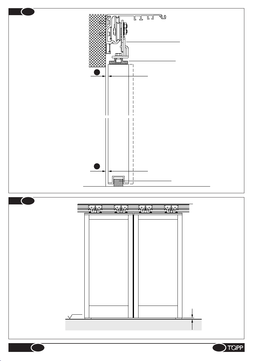
Lower carriage bracket
Standard adapter
Runner on floor
A
A
Fig. 17
LPF
Fig. 18
5
15
INSTRUCTIONS FOR INSTALLATION AND USE
EN
K200

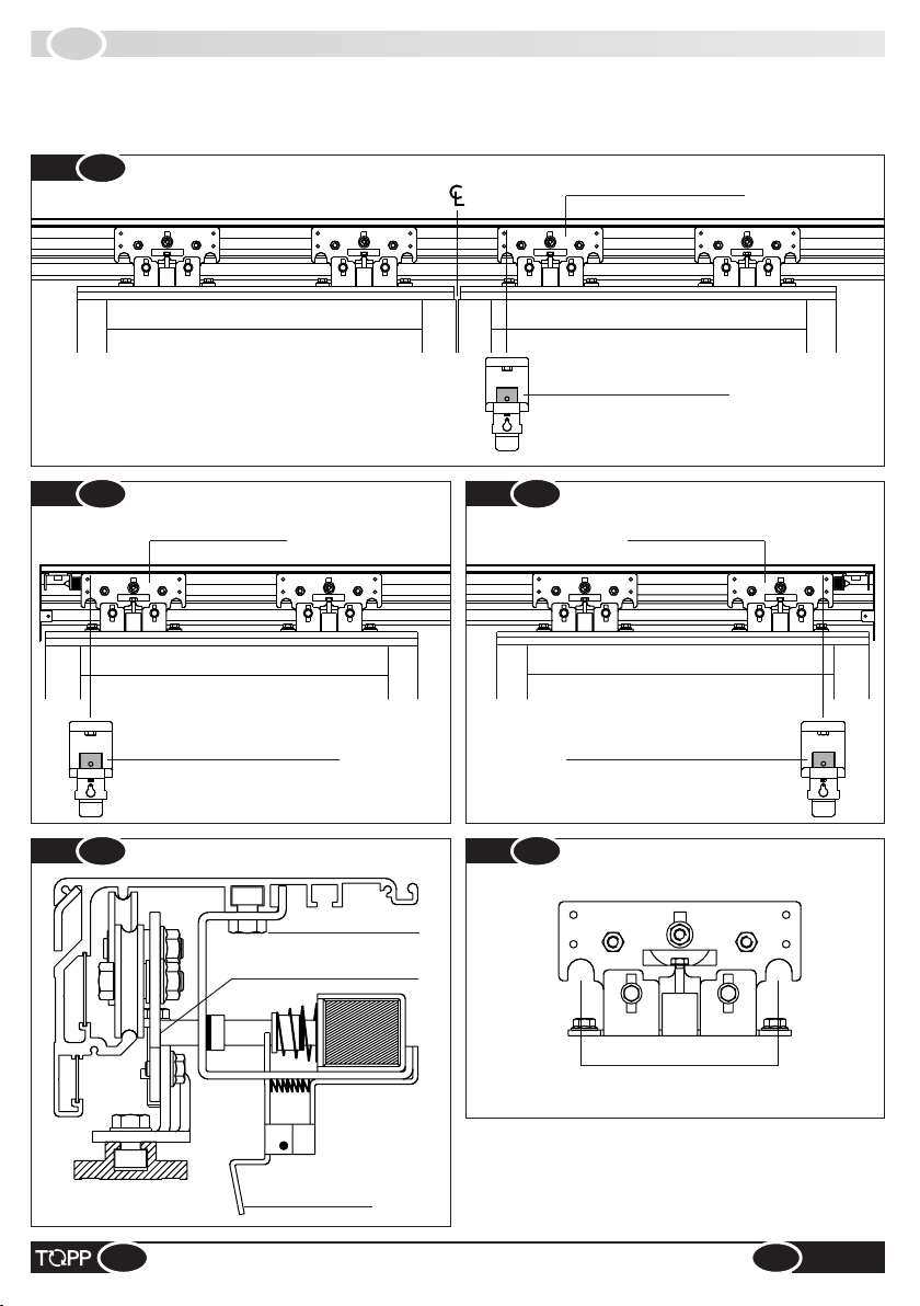
3.6
INSTALLING THE MOTOR MODULE, BELT TRANSMISSION, BELT,LOGLINE
K200 - model with 2 door
panels (Fig.19)
K200 - model with
1 door panel (Fig.20)
16
INSTRUCTIONS FOR INSTALLATION AND USE
2700 17601760 2 x 3504
2800 1812 1812 2 x 3608
1000 876 876 2 x 1736
1100 928 928 2 x 1840
1200 980 980 2 x 1944
1300 1032 1032
2 x 2048
1400 1084 1084 2 x 2152
1500 1136 1136 2 x 2256
1600 1188 1188 2 x 2360
1700 1240 1240 2 x 2464
1800 1292 1292 2 x 2568
1900 1344 1344 2 x 2672
2000 1396 1396 2 x 2776
2100 1448 1448 2 x 2880
2200 1500 1500 2 x 2984
2300 1552 1552 2 x 3088
2400 1604 1604 2 x 3192
2500 1656 1656 2 x 3296
2600 1708 1708 2 x 3400
VPA AB
L Belt
L Logline
1700 120 1994 1 x 3976
1800 120 2098 1 x 4184
1900 120 2202 1 x 4392
2000 120 2306 1 x 4600
2100 120 2410 1 x 4808
2200 120 2514 1 x 5016
2300 120 2618 1 x 5224
2400 120 2722 1 x 5432
2500 120 2826 1 x 5640
2600 120 2930 1 x 5848
2700 120 3034 1 x 6056
2800 120 3138 1 x 6264
1000 120 1266 1 x 2520
1100 120 1370 1 x 2728
1200 120 1474 1 x 2936
1300 120 1578
1 x 3144
1400 120 1682 1 x 3352
1500 120 1786 1 x 3560
1600 120 1890 1 x 3768
VPA A
800 120 1058 1 x 2104
900 120 1162 1 x 2312
VPA AB
L Belt
L Logline
942
1046
1150
1254
1358
1462
1566
1670
1774
1878
1982
2086
2190
2294
2398
2502
2606
2710
2814
248
352
456
560
664
768
872
976
1080
1184
1288
1392
1496
1600
1704
1808
1912
2016
2120
2224
2328
EN K200
MOTOR MODULE
1 RIGHT DOOR PANEL
Lower belt bracket – front carriage – panel opening toward the right
B
A
BELT TRANSMISSION
BELT TENSION ADJUSTMENT
1 LEFT DOOR PANEL A
B
MOTOR MODULE
Upper belt bracket – front carriage – panel opening toward the left
BELT TRANSMISSION
BELT TENSION ADJUSTMENT
Fig. 20
2 DOOR PANELS
Lower belt bracket – front carriage – panel opening toward the right
Upper belt bracket – front carriage – panel opening toward the left
B
BELT TRANSMISSION
BELT TENSION ADJUSTMENT
Fig. 19
MOTOR MODULE
A
C
L

17
INSTRUCTIONS FOR INSTALLATION AND USE
EN
K200
-Mark the reference measurements on the crossbar using
the tables on page 16;
Installing the belt transmission (Fig.22):
Installing the transmission belt (Fig. 23a, 23b):
Before installing the motor module, belt transmission and
belt on the crossbar, prepare and install the wires necessary
for the electrical connections and make sure the carriages,
door panels and runners on the floor have been fully
adjusted and positioned.
Installing the motor module (Fig.21):
-To tighten the belt, loosen screws “VTF” on the
transmission and turn screw “C” to obtain the proper belt
tension.
-Fit the motor module with the slots provided for fastening in
the VTM screws, check the reference mark on the crossbar
once more and tighten the VTM screws.
-Mark the reference measurements on the crossbar using
the tables on page 16;
-Loosen the two VTM screws on the crossbar for fastening
the motor module;
-Remove the two VTF screws on the crossbar for fastening
the belt transmission;
-Fit the transmission with the specific fastening holes in the
VTF screws and tighten them;
-Install the transmission belt on the motor and transmission
pulley making sure the belt junction brackets are positioned
as shown in Fig.24. (Upper bracket for door opening to the
left, lower bracket for door opening to the right).
-To check the tension, with the handshake bring the two
edges of the belt as shown in Fig. 23b.The tension is
enough if there is some resistance before the contact of the
two edges.
-Tighten screws “VTF” after checking that the transmission
is aligned with the crossbar.
-Fig.23a Slightly loosen screws “A” on the tension
adjustment, take the belt transmission to the end of its run
and tighten screws “A”.
Fig. 23b
belt trasmission
Motor module
Fig. 23a
ABelt
tension
VTF
C
Fig. 21
No. 6 hexagonal wrench
VTM
Motor module
nut
Fig. 22
transmission
VTF
No. 6 hexagonal wrench
nut
Belt
adjustment

3.7
FASTENING DOOR DRIVE BRACKETSE
2 DOORS – simultaneous opening toward the right and left
DOOR OPENING TO RIGHT DOOR OPENING TO LEFT
M6x8 screws
M6x10 screws
Upper belt bracket
M6x8 screws
M6x10 screws
Upper belt bracket
Left front door carriage Right front door carriage
Horizontal adjustment slots
Door drive bracket
Horizontal adjustment slots
Door drive bracket
C
L
Fig. 24
18
INSTRUCTIONS FOR INSTALLATION AND USE
EN K200

1 LEFT DOOR – opening toward the left
1 RIGHT DOOR – opening toward the right
Front door carriage
Horizontal adjustment slots
Screws M6x8
Screws M6x10
Lower belt bracket
Door drive bracket
M6x8 screws
M6x10 screws
Upper belt bracket
Front door carriage
Horizontal adjustment slots
Door drive bracket
Fig. 25
Fig. 26
19
INSTRUCTIONS FOR INSTALLATION AND USE
EN
K200
3.8
INSTALLING THE DOOR BLOCK
Right door front carriage
Door block with manual
release incorporated
Front carriage Front carriage
Door block with manual
release incorporated
Door block with manual
release incorporated
2 DOOR PANELS
1 RIGHT DOOR PANEL 1 LEFT DOOR PANEL
Carriage block fastener
Manual release
Carriage block fastener
Fastening screw
During installation, make sure that when the door is closed with the block on, it must be possible to open the door manually
by at least 2-3 mm. This tolerance is necessary to enable the block to be released without difficulty.
Fig. 27
Fig. 28 Fig. 29
Fig. 30
Attention!: The door block system is not to be considered
as a device for protection against break-ins.
To release and open the door, push the manual release
lever under the casing forward and, at the same time, pull
the door with your hand until it opens.
Fig. 31
20
INSTRUCTIONS FOR INSTALLATION AND USE
EN K200
Table of contents
Other TOPP Door Opening System manuals


