manuals.online logo
Brands
  1. Home
  2. •
  3. Brands
  4. •
  5. Assa Abloy
  6. •
  7. Door Opening System
  8. •
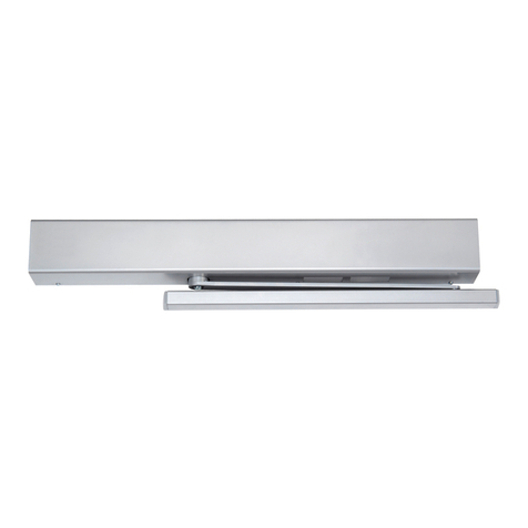
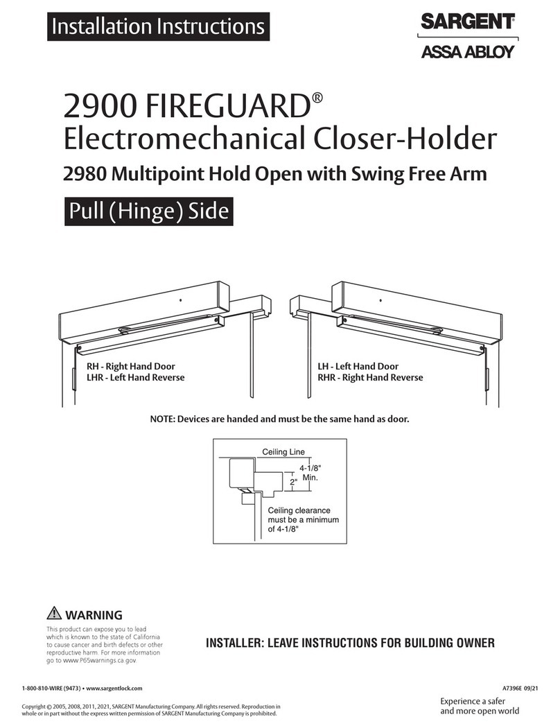
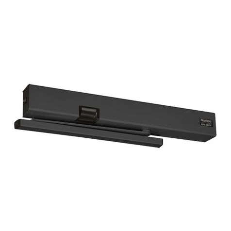
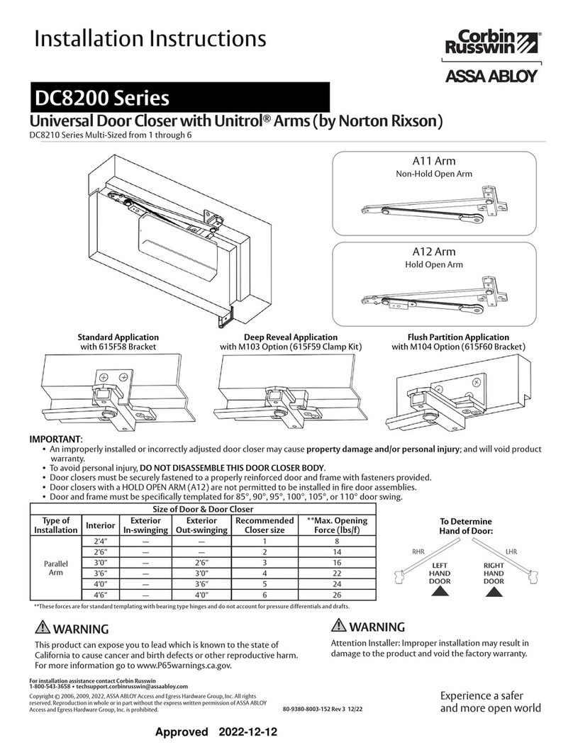
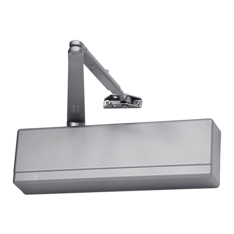
  9. Assa Abloy SARGENT Powerglide 281 Series User manual

Assa Abloy SARGENT Powerglide 281 Series User manual

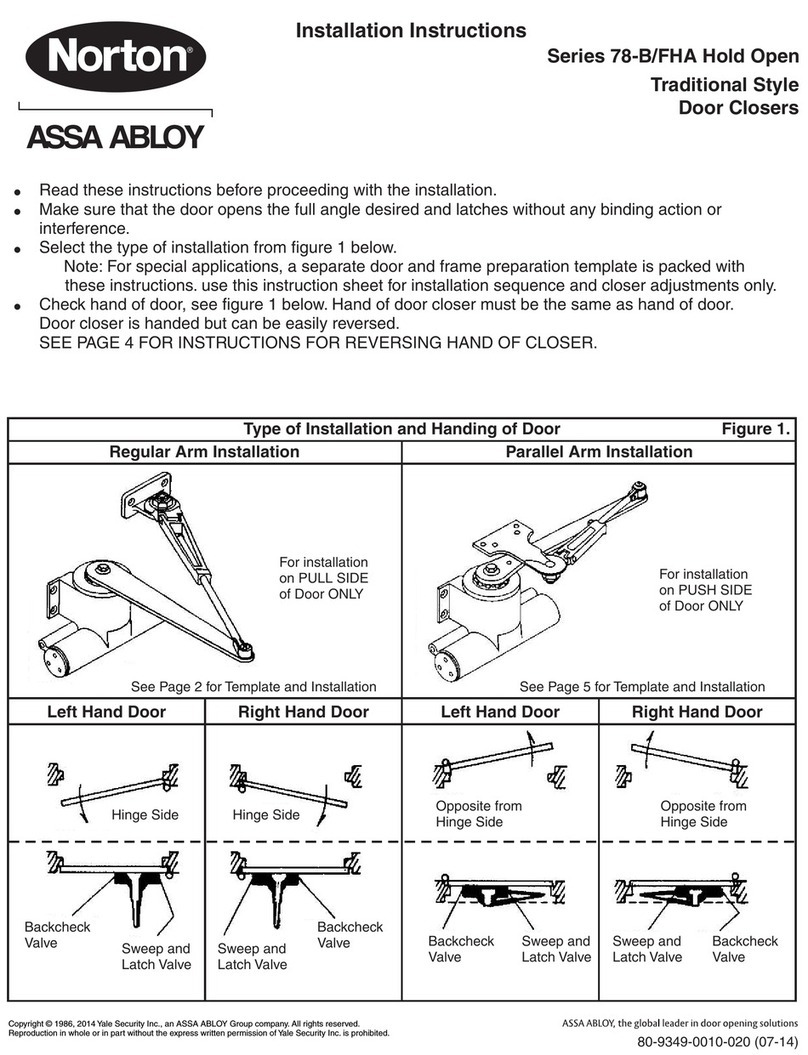
Closer mounted to frame
on stop side of door.
Top Jamb Application
(Type 25-O, 25-OZ, and 25-OZA Arms)
Use instructions on page 4
Standard Application
(Type 25-O Arm)
Use instructions on page 3
Closer mounted
on hinge side of door.
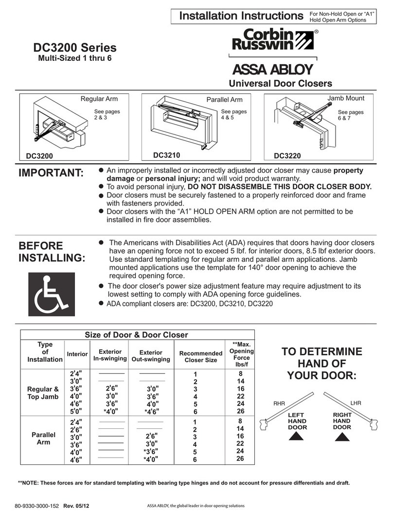
Parallel Arm Application
(Type 25-P9)
Use instructions on page 5
Closer mounted
on stop side of door.
NOTE: For 08 and OLC type arms mounting,
see data sheets provided with arm.
1-800-727-5477 • www.sargentlock.com
A7278F 12/22 Rev 6
Installation Instructions
281 Powerglide Series
Closer with Regular Arms (Without Holder)
281 Series Non Sized Adjustable from Sizes 1 thru 6
Copyright © 2003, 2008, 2014, 2020, 2022, SARGENT Manufacturing Company. All rights reserved. Reproduction in whole or in part without the
express written permission ofSARGENT Manufacturing Company is prohibited. Patent pending and/or patent www.assaabloydss.com/patents.
Approved 2022-12-08
Standard and Top Jamb Applications
Number of Turns of Spring Power Adjusting Screw
From Factory Setting (Use Chart as Guide ONLY)
Door Width
in (mm)
Approximate
Door Weight (Pounds)
281 Exterior
Doors
Interior
Doors *
24 (610) 80 Factory Set —
30 (762) 110 1-5 CW
32 (813) 115
1-5 CCW36 (914) 130 5-8 CW
40 (1016) 150
42 (1067) 155 8-13 CW Factory Set
44 (1118) 165
46 (1168) 170 13-15 CW 1-5 CW
48 (1219) 180
over 48 (1219) — up to 19 CW as req. 5 CW & up as req.
LEFT
HAND DOOR
RIGHT
HAND DOOR
PULL
HINGE SIDE PULL
HINGE SIDE
STOP (PUSH) SIDE STOP (PUSH) SIDE
+-
Increase
Power Decrease
Power
Counterclockwise
(CCW)
Clockwise
(CW)
1/4" Allen Spring Power
Adjusting Screw
Parallel Arm Application Only
Number of turns of Spring Power Adjusting Screw
From Factory Setting (Use Chart as Guide ONLY)
Door Width
in (mm)
Approximate
Door Weight (Pounds)
281 Exterior
Doors
Interior
Doors*
24 (610) 80 2-7 CW —
30 (762) 110
32 (813) 115 7-11 CW 1-5 CCW
36 (914) 130
40 (1016) 150
11-15 CW Factory Set
42 (1067) 155
44 (1118) 165
1-8 CW46 (1168) 170 15-17 CW
48 (1219) 180
over 48 (1219) — up to 19 CW as req. 8 CW & up as req.
To Determine Your Hand of Door
Spring Power Adjustment
Adjust spring according to the
appropriate application chart.
*If interior doors do not have to comply with ADA requirements, exterior door
settings are recommended. Where strong drafts exist, increase spring power as
needed by turning spring adjustment screw clockwise. If necessary, reduce spring
power by turning screw counterclockwise.
2
1-800-727-5477 • www.sargentlock.com A7278F 12/22 Rev 6
281 Series
Installation Instructions
Closer with Regular Arms
Copyright © 2003, 2008, 2014, 2020, 2022, SARGENT Manufacturing Company. All rights reserved. Reproduction in
whole or in part without the express written permission ofSARGENT Manufacturing Company is prohibited. Patent
pending and/or patent www.assaabloydss.com/patents.
Approved 2022-12-08
1. Prepare door and frame.
2. Mount bracket and closer to door.
3. Attach foot and pivot to frame.
Attach foot to frame with pivot away from hinge.
You’ve installed the 281 Powerglide Series Closer - Standard Mount.
🛑
Go to page 6 for closer adjustments and cover installation.
1
2
3
4
5
Arm
Screw
Swivel Arm
Rod
Position of Main Arm
when Assembling to
spindle Index Mark
on Spindle
Main Arm
4. Attach Arm.
Attach arm with index mark on spindle aligned as shown. Secure with screw
and washer. Insert rod end into swivel arm and tighten arm screw.
Arm
Type Mounting Max Door
Opening Dim A Dim B
Regular
Arm
No
Holder
Standard 120° 7" 12-1/8"
Alternate 160° 5" 10-1/8"
If Butt, Frame, and Wall conditions permit, door will open 180°
NOTES:
1. Right hand door shown, left hand door opposite.
2. This dimension is taken from hinge edge of door for invisible hinges.
3. Drill and tap and use screws provided or use mortise nuts when required.
Pivot
Dim B
Dim
A
1-1/4" 2"
#12 x 1-1/2 Wood Screws or
#12-24 x 5/8 Flat Head
Machine Screws
7/8"
10-3/8"
Top of
Door
1"
of Hinge Pivot:
Butts, offset Pivots, Swing Clear,
Center Hung, or Invisible hinges
Alternate mounting is recommended
for ADA compliant doors
Install mounting
bracket with arrow
pointing up for both
RH and LH doors.
Install Closer with
Spring Adjustment
Screw away from
hinge.
Use Mounting bracket
as drill thru template
Right Hand
Door Shown
Right Hand Door Shown (Left Hand Door Opposite)
281 Standard Application Instructions
3
1-800-727-5477 • www.sargentlock.com
281 Series
Installation Instructions
Closer with Regular Arms
Copyright © 2003, 2008, 2014, 2020, 2022, SARGENT Manufacturing Company. All rights reserved. Reproduction in
whole or in part without the express written permission ofSARGENT Manufacturing Company is prohibited. Patent
pending and/or patent www.assaabloydss.com/patents.
A7278F 12/22 Rev 6
Approved 2022-12-08
281 Top Jamb Application Instructions
1. Prepare door and frame.
3. Attach foot and pivot.
You’ve installed the 281 Powerglide Series Closer - Top Jamb Mount.
🛑
Go to page 6 for closer adjustments and cover installation.
Attach foot
to door with
pivot away from
hinge.
Arm Type Reveal Depth Dim A Max Door
Opening
"O" Arm 0" to 2" 9-5/16" 180°
"OZ" Arm 2-1/8" to 5" 10-1/8" 140°
"OZA" Arm 5-1/8" to 8" 10-15/16" 140°
IMPORTANT: Use alternate mounting if door can open beyond limits shown
for standard mounting.
NOTES:
1. Left hand door shown. Right hand door opposite.
2. These dimensions may be reduced to 3/8" min. if rail on top casing is
narrow or low ceiling condition exists. Foot placement should be moved
accordingly.*
3. This dimension is taken from hinge edge of door for invisible hinges.
4. Drill and tap and use screws provided or use mortise nuts when required.
4. Install main arm and spindle.
2. Mount bracket and closer to door.
Use Mounting bracket
as drill-through template
Install mounting
bracket with arrow
pointing down for
both RH and LH doors.
Install Closer with
Spring Adjustment
Screw away from
hinge.
Right Hand
Door Shown
Right
Angle
Rod
Swivel
Arm 45°
Position of Main Arm When
Assembling to Spindle
Right Hand Door
Arm
Screw
C
L
Dim
A
3-5/8"
2"
#12 x 1-1/2 Wood Screws or
#12-24 x 5/8 Flat Head
Machine Screws
10-3/8"
Top of
Door
1"
of Pivot
Hinge
Frame
5/8"
*1-5/8 "
Left Hand
Door Shown
Spring Power
Adjustment
Screw
Index mark on
spindle
View looking up when
assembling arm to spindle
Right Hand
Door Shown
Left Hand
Door Shown
Main Arm
Main Arm
View Looking Up
4
1-800-727-5477 • www.sargentlock.com A7278F 12/22 Rev 6
281 Series
Installation Instructions
Closer with Regular Arms
Copyright © 2003, 2008, 2014, 2020, 2022, SARGENT Manufacturing Company. All rights reserved. Reproduction in
whole or in part without the express written permission ofSARGENT Manufacturing Company is prohibited. Patent
pending and/or patent www.assaabloydss.com/patents.
Approved 2022-12-08
281 Parallel Arm Application Instructions
1. Prepare door and frame.
4. Assemble the spindle.
Max Door
Opening Dim A Dim B
120° 4-1/2" 10-1/2"
*180° 1-5/8" 7-5/8"
NOTES:
1. Left hand door shown. Right hand opposite.
2. Do not use this mounting for "swing clear" hinges.
3. This dimension is taken from hinge edge of door for
invisible hinges.
4. May be reduced by 1/2" to avoid door trim.
Drill & tap and use screws provided or use mortise nuts
when required.
2. Mount bracket and closer. 3. Attach foot bracket to frame stop.
Optional arms for mounting.
(Refer to data sheets provided with arm)
Remove backing from self adhesive tape
and use bracket as drill-through template.
C
L
C
L
Dim A
2-1/2"
#12 x 1-1/2
Wood Screws or
#12-24 x 5/8 Flat Head
Machine Screws
10-3/8"
Top of
Door
1"
of Hinge Pivot
Stop
5/16"
of Bracket
Dim B
Door
1-1/4" #12 x 1-1/2
Wood Screws or
#12-24 x 5/8 Flat Head
Machine Screws
7/8"
1/2"
Hinge Pivot:
Butt, Offset Pivots, Swing Clear,
Center hung or Invisible hinges
3"
Install mounting
bracket with arrow
pointing up for both
RH and LH doors.
Install Closer with
Spring Adjustment
Screw towards hinge.
Right Hand
Door Shown
For flush frame and door conditions
For use with overhead
door holders
P4 or P4A
Bracket
P3 or P3A
Bracket (Sargent #590
shown)
P4A bracket is used with overhead doors
Approx 45°
1
2
3
4
5
Main Arm
Main Arm
1
2
3
4
5
Right Hand
Door
Left Hand
Door
Index Mark on
Spindle
Index Mark on
Spindle
You’ve installed the 281 Powerglide Series Closer - Parallel Arm Mount.
🛑
Go to page 6 for closer adjustments and cover installation.
CAUTION: Door closer will not
operate properly if main arm is
not indexed correctly.
5
1-800-727-5477 • www.sargentlock.com
281 Series
Installation Instructions
Closer with Regular Arms
Copyright © 2003, 2008, 2014, 2020, 2022, SARGENT Manufacturing Company. All rights reserved. Reproduction in
whole or in part without the express written permission ofSARGENT Manufacturing Company is prohibited. Patent
pending and/or patent www.assaabloydss.com/patents.
A7278F 12/22 Rev 6
Approved 2022-12-08
++
Regulating Door Speed and Latching as Needed
Use hex socket (1/8" Allen) wrench and turn valves
clockwise to slow down or counterclockwise to speed up
door movement.
Faster
(+) Slower
(–)
Regulating Backcheck
To regulate the intensity of backcheck action, turn valve
clockwise to increase or counterclockwise to decrease
checking
Decrease
(–) Increase
(+)
CAUTION: Set valve for slight cushioning effect. It is damaging to
the closer if the checking action is too abrupt. Never use backcheck
as a door stop. ALWAYS USE DOOR STOP TO STOP THE DOOR
For Models with Optional Delayed Action Feature
"Delayed Action" provides slow door closing through
delayed action range.
Turn valve clockwise to slow down or counterclockwise
to speed up door movement.
Faster
(+) Slower
(–)
Adjusting Foot for Additional Closing Power
(For Standard and Top Jamb Applications Only)
Move foot
Pivot to hole
nearest hinge
Final Adjustment and Regulating Procedure
Latching
Speed Range
Closing Speed
Range
Delayed
Action Range
Backcheck
Range
Latching
Speed
Valve
Closing
Speed
Valve
Delayed
Action
Valve
(Optional)
Backcheck
Valve
1/4" Spring Power
Adjustment Screw
Hinge Edge of Door
Install Cover
Install cover with two (2) screws as shown.
Insert is removable.
Place in unused opening.
6
1-800-727-5477 • www.sargentlock.com A7278F 12/22 Rev 6
281 Series
Installation Instructions
Closer with Regular Arms
Copyright © 2003, 2008, 2014, 2020, 2022, SARGENT Manufacturing Company. All rights reserved. Reproduction in
whole or in part without the express written permission ofSARGENT Manufacturing Company is prohibited. Patent
pending and/or patent www.assaabloydss.com/patents.
Approved 2022-12-08
Using Mortise Nuts with Sargent Door Closers
NOTES:
1. See instruction or data sheet packed with door closer for dimensions locating the closer body and foot on door and frame.
2. Mortise nut shown is designed for unreinforced metal doors.
3. For top jamb and corner bracket applications: The door closer foot will be attached to the door in a manner similar to that shown
for mounting the closer body.
4. For doors 2-1/4" thick: Mortise nut shown for 1-3/4" thick doors will be furnished along with appropriate length thru-bolts. Door
construction must provide a bridge type reinforcement to prevent the door rail from collapsing when thru-bolts are tightened.
Frame
Door Stop
Mortise Nut Head
Drill 3/8" Dia. hole
for Mortise Nut
body.
Door
Drill 1/4" Dia. hole
for mounting screws
Cover
Sargent 1430 Series Closer Shown
(Other series similar)
See Note #1 above for dimension
information. If a dimension is less than
7/8" is used. The door stop must be cut
to clear the Mortise nut head or the
Mortise nut head must be recessed.
(See enlarged view "Y")
Frame
Door
Stop
Mortise Nut
Head
Shorten Mortise
nut body to this
length
351 Door closer
shown. (Track assembly
mounting is similar)
3/8" Dia. hole
View "Y"
1/4" Dia.
drilled hole
351 Door Closer Shown
1/8"
5/8" Dia. hole
Mortise Nut
9/16"
Dia.
#12-24 Thread
1-11/16" for 1-3/4" thick door
1-5/16" for 1-3/8" thick door
(See Note #4 above for 2-1/4" thick doors)
7/64"
7
1-800-727-5477 • www.sargentlock.com
281 Series
Installation Instructions
Closer with Regular Arms
Copyright © 2003, 2008, 2014, 2020, 2022, SARGENT Manufacturing Company. All rights reserved. Reproduction in
whole or in part without the express written permission ofSARGENT Manufacturing Company is prohibited. Patent
pending and/or patent www.assaabloydss.com/patents.
A7278F 12/22 Rev 6
Approved 2022-12-08
A7278F 12/22 Rev 6
Attention Installer: Improper installation
may result in damage to the product and
void the factory warranty.
WARNING
WARNING
This product can expose you to lead which is known to the state of California to
cause cancer and birth defects or other reproductive harm. For more information
go to www.P65warnings.ca.gov.
1-800-727-5477 • www.sargentlock.com
Copyright © 2003, 2008, 2014, 2020, 2022, SARGENT Manufacturing Company. All rights reserved. Reproduction in
whole or in part without the express written permission ofSARGENT Manufacturing Company is prohibited.
Patent pending and/or patent www.assaabloydss.com/patents.
Approved 2022-12-08

Other Assa Abloy Door Opening System manuals
Assa Abloy Norton 7200 Series Quick guide

Assa Abloy

Assa Abloy Norton 7200 Series Quick guide

Assa Abloy Besam SL500 User manual

Assa Abloy

Assa Abloy Besam SL500 User manual

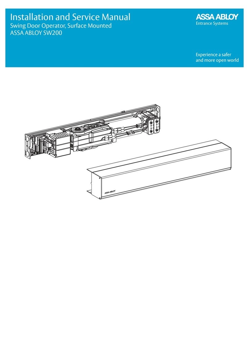
Assa Abloy SW200 User manual

Assa Abloy

Assa Abloy SW200 User manual

Assa Abloy Norton 6300 Series Quick guide

Assa Abloy

Assa Abloy Norton 6300 Series Quick guide

Assa Abloy Corbin Russwin DC8200 Series User manual
Assa Abloy

Assa Abloy Corbin Russwin DC8200 Series User manual

Assa Abloy DC3210 Series User manual

Assa Abloy

Assa Abloy DC3210 Series User manual

Assa Abloy Corbin Russwin PED5200 User manual

Assa Abloy

Assa Abloy Corbin Russwin PED5200 User manual

Assa Abloy DC700 User manual

Assa Abloy

Assa Abloy DC700 User manual

Assa Abloy Corbin Russwin PED5000 DB Series User manual

Assa Abloy

Assa Abloy Corbin Russwin PED5000 DB Series User manual

Assa Abloy SW60 Manual

Assa Abloy

Assa Abloy SW60 Manual

Assa Abloy G-CO-C User manual

Assa Abloy

Assa Abloy G-CO-C User manual

Assa Abloy Lockwood 724 Series User manual

Assa Abloy

Assa Abloy Lockwood 724 Series User manual

Assa Abloy G-CO-FMS User manual

Assa Abloy

Assa Abloy G-CO-FMS User manual

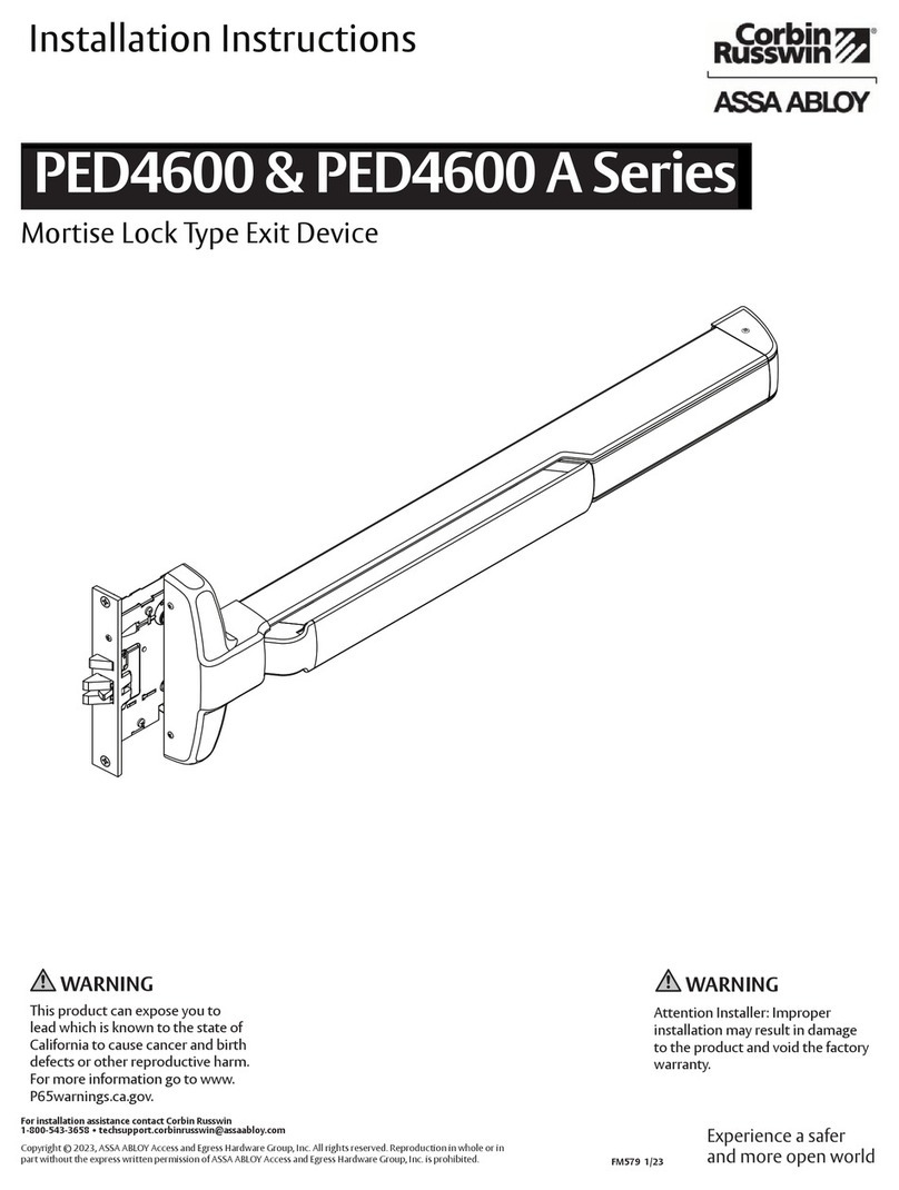
Assa Abloy Corbin Russwin PED4600 A Series User manual
Assa Abloy

Assa Abloy Corbin Russwin PED4600 A Series User manual

Assa Abloy Norton 7500 Series User manual

Assa Abloy

Assa Abloy Norton 7500 Series User manual

Assa Abloy Norton 5900 Series Quick guide

Assa Abloy

Assa Abloy Norton 5900 Series Quick guide

Assa Abloy Norton 6300 Series Quick guide

Assa Abloy

Assa Abloy Norton 6300 Series Quick guide

Assa Abloy Besam VersaMax ICU User manual

Assa Abloy

Assa Abloy Besam VersaMax ICU User manual

Assa Abloy Norton 9500 Series User manual

Assa Abloy

Assa Abloy Norton 9500 Series User manual

Assa Abloy Norton 1600H Series User manual

Assa Abloy

Assa Abloy Norton 1600H Series User manual

Assa Abloy RIXSON W73ER User manual

Assa Abloy

Assa Abloy RIXSON W73ER User manual

Assa Abloy Norton LEO 5700 Series User manual

Assa Abloy

Assa Abloy Norton LEO 5700 Series User manual

Assa Abloy NORTON RIXSON 1600 Series User manual

Assa Abloy

Assa Abloy NORTON RIXSON 1600 Series User manual

Assa Abloy MAB 609 + AC593 Instruction Manual

Assa Abloy

Assa Abloy MAB 609 + AC593 Instruction Manual

Popular Door Opening System manuals by other brands

ONLEVEL Banana Slide 50 installation instructions

ONLEVEL

ONLEVEL Banana Slide 50 installation instructions

Allegion LCN 8310-836T quick start guide

Allegion

Allegion LCN 8310-836T quick start guide

Dormakaba Best EHD9000 PT installation instructions

Dormakaba

Dormakaba Best EHD9000 PT installation instructions

Lamp FM150PRO installation manual

Lamp

Lamp FM150PRO installation manual

Nabco GT20 Programming manual

Nabco

Nabco GT20 Programming manual

MANTION SMT WIBAT APPLIQUE installation instructions

MANTION SMT

MANTION SMT WIBAT APPLIQUE installation instructions

BWI 416 Series installation instructions

BWI

BWI 416 Series installation instructions

BFT K 130 manual

BFT

BFT K 130 manual

Nabco Acusensor 3 instruction manual

Nabco

Nabco Acusensor 3 instruction manual

LCN 4050 Series installation instructions

LCN

LCN 4050 Series installation instructions

Tucker Auto-Mation SW10 installation guide

Tucker Auto-Mation

Tucker Auto-Mation SW10 installation guide

MS Sedco CleraPath Spectrum S-COR installation instructions

MS Sedco

MS Sedco CleraPath Spectrum S-COR installation instructions

GTO/PRO EXIT WAND installation manual

GTO/PRO

GTO/PRO EXIT WAND installation manual

CDVI Digiway SR Easy start guide

CDVI

CDVI Digiway SR Easy start guide

Besam PowerSwing installation manual

Besam

Besam PowerSwing installation manual

Auta 700105 manual

Auta

Auta 700105 manual

CRL JACKSON 300 Series installation instructions

CRL

CRL JACKSON 300 Series installation instructions

Dormakaba Muto Premium XL120 installation instructions

Dormakaba

Dormakaba Muto Premium XL120 installation instructions

manuals.online logo
manuals.online logoBrands
  • About & Mission
  • Contact us
  • Privacy Policy
  • Terms and Conditions

Copyright 2025 Manuals.Online. All Rights Reserved.