manuals.online logo
Brands
  1. Home
  2. •
  3. Brands
  4. •
  5. Dimplex
  6. •
  7. Heater
  8. •
  9. Dimplex AC3CN User manual

Dimplex AC3CN User manual

08/19239/1 - Issue 1
The product complies with the European Safety Standards EN60335-2-30 and the European Standard Electromagnetic Compatibility
(EMC) EN55014, EN60555-2 and EN60555-3 which cover the essential requirements of EEC Directives 73/23 and 89/336
AC3CN Recessed Ceiling Heater / Over Door Heater
1
2
‘C’
‘B’ ‘A’‘D’ 6
‘1’
‘2’ ‘3’
C
M
T
‘1’ ‘2’ ‘3’
NLNMH1 H2
DF SF SF SF
SF
DF
EE
B
C
T
ss ss
4
4
0mm min.
min.
200
200
mm
min.
min.
70
70
mm max.
max.
'y'
'x'
'C'
1 2
5 6
7
3
8
4
‘e’ ‘e’‘f’ ‘f’
‘g’ ‘g’
‘B’
‘
A
’
‘B’
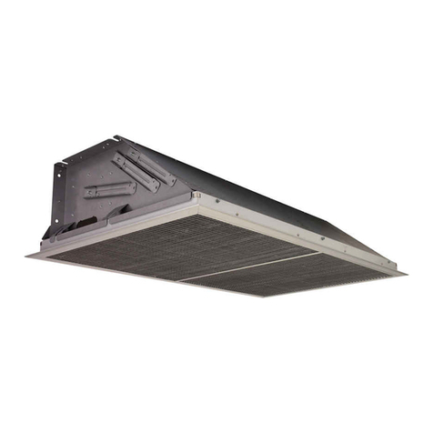
Recessed Ceiling Heater / Over Door Heater
Model: AC3CN
IMPORTANT: THESE INSTRUCTIONS SHOULD BE READ CAREFULLY AND RETAINED FOR FUTURE REFERENCE
WARNING: Ensure power cable path does not come into contact with
internal heater elements or fans.
Make connections as per wiring Diagram (see Fig. 8) and replace the
base cover.
Labels Description
BBLOWER MOTOR
EHEATER ELEMENT
TTERMINAL BLOCK
CPOWER CABLE FROM SWITCH PANEL
(Typically 5 core - NOT SUPPLIED)
Connection of Switch Panel
The mains electrical supply cable and power cable to this heater (neither
supplied) should be connected as per the wiring diagram shown in
Fig. 7 (see Fig. 3 for Switch No.’s).
Labels Description
‘1’ ON - OFF (Single Pole Switch)
‘2’ HALF HEAT (Single Pole Switch)
‘3’ SECOND HALF HEAT (Single Pole Switch)
T TERMINAL BLOCK
C POWER CABLE TO HEATER
(Typically 5 core - NOT SUPPLIED)
M MAINS IN POWER CABLE (NOT SUPPLIED)
∗Test all switch settings once installation is complete ∗
Installation of Heater
The Installation of this product must only be carried out by a
prescribed competent person in accordance with Building
Regulations (Part P) and the current IEE Wiring Regulations for
electrical equipment.
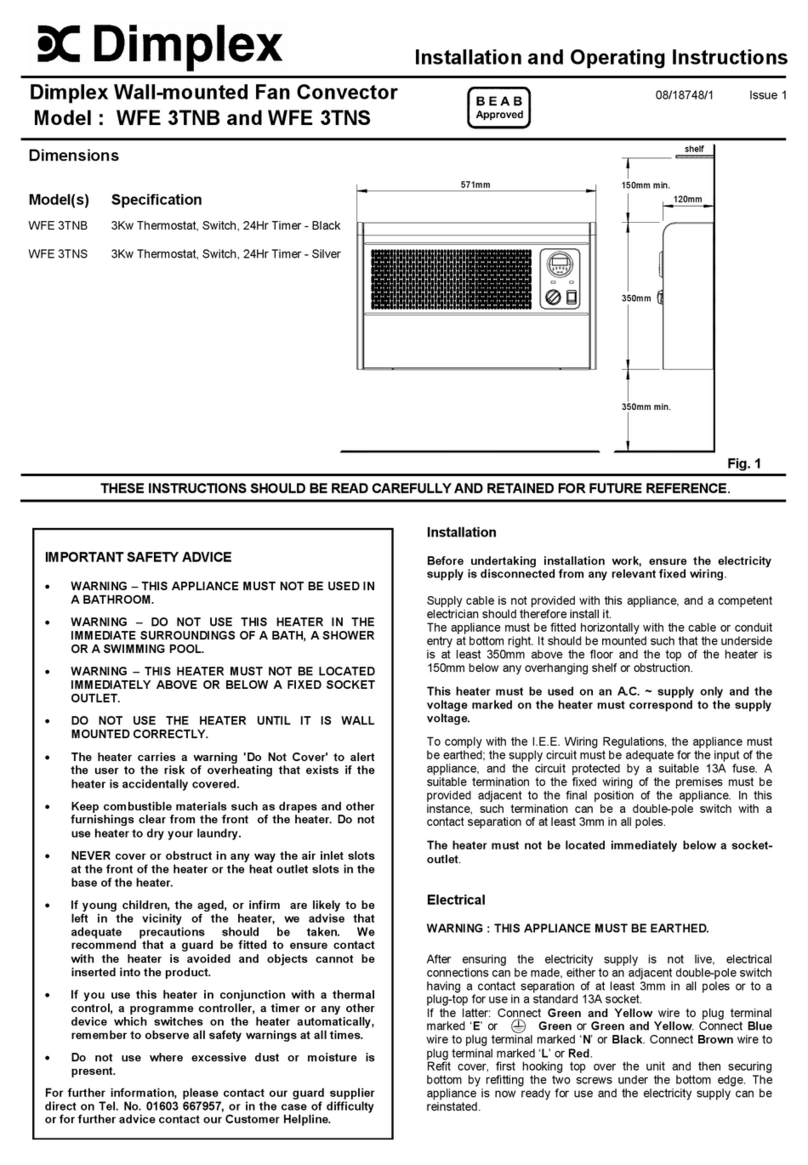
This heater can either be installed into a suspended or plasterboard
ceiling. First it is necessary to ensure that 200mm of sufficient space
exists above the ceiling for the Installation of this product (see Fig. 1
and Fig. 2).
This product is designed to be suspended by threaded rod or
wires/chains. Always ensure this unit is adequately supported when
installed.
Installation in a plasterboard (or similar) Ceiling
A hole (610x610mm) as indicated in Fig. 1 must be cut into the ceiling.
It may be necessary to fix an internal supporting frame around the newly
cut aperture in a plasterboard ceiling.
The heater can then be installed in the ceiling void as detailed in the
‘Mounting of Appliance’ section and on completion of ‘Electrical
Connection’, the Ceiling grille assembly (see ‘A’ in Fig. 1 and Fig. 5)
can then be fixed into position.
Installation in a Suspended Ceiling
A standard 600 x 600mm ceiling tile needs to be removed as close to
the final position of the product as possible.
The heater can then be installed in the ceiling void as detailed in the
‘Mounting of Appliance’ section and on completion of ‘Electrical
Connection’, only the supplied egg crate grille core should be fitted into
position replacing the old ceiling tile.
Mounting of Heater
In order to mount the unit into the ceiling void, use lengths of threaded
bar or hooks (not supplied) screwed into the M8 threaded inserts located
in the top side of the heater (see Fig. 1 for dimensions). Adjust the
height of the heater so the air inlet/outlet panel (see ‘B’ in Fig. 1 and
Fig. 5) is positioned inside the grille frame and no more than 70mm
above the installed height of the egg crate grille which allows access for
future maintenance. The unit should also be positioned inside the grille
opening to achieve optimum air-flow effect, as shown in Fig. 2.
IMPORTANT SAFETY ADVICE
Warning - Disconnect from the mains supply before carrying
out maintenance.
DO NOT COVER OR OBSTRUCT the air inlet/outlet ceiling grille.
A minimum distance of 1.5 metres must be observed between
the ceiling grille and any furniture, combustible material or
furnishings.
ENSURE THIS PRODUCT IS EARTHED.
Ensure the supply cables are of adequate current carrying
capacity and are protected by a suitable fuse.
A suitable termination to the fixed wiring of the premises must
be provided adjacent to the final position of the Switch Panel.
This heater must not be located immediately above or below a
fixed socket outlet or connection box.
This product must not be subjected to water spray or immersion
and should be mounted such that no part of it can be touched
by a person using a fixed bath or shower.
DO NOT use the heater in the immediate surroundings of a bath,
a shower or a swimming pool.
DO NOT use this heater in areas where excessive dust exists.
This product should be mounted safely into ceiling areas only.
The ceiling can be either of a plasterboard (or similar)
construction, or of suspended 600 x 600mm ceiling tiles.
DO NOT store or use any flammable materials or sprays in the
vicinity of the heater – FIRE HAZARD.
DO NOT insert any foreign objects into the heater openings.
Risk of injury, electric shock or damage to the heater may occur.
Ensure proper manual handling procedures are observed at all
times.
Model Loading Current Voltage
(kW) (amps) (volts)
AC3CN 3 13 ∼230-240
General
The carton contains: -
1 AC3CN heater
1 Ceiling grille assembly (frame + egg crate core)
1 Switch Box
This Recessed Ceiling Heater / Over Door Heater is a robust heater
intended for installation into a suspended or plasterboard ceiling.
For optimum results, do not install this product in ceilings higher than 3
metres. If multiple heaters are installed, generous spacing should be
provided between heaters to achieve an even heating distribution.
Electrical Connection
The Electrical Connection of this product should be carried out by a
competent electrician and be in accordance with the current IEE wiring
regulations before replacing the bottom cover.
A suitable local isolating switch must be provided in the electrical supply
circuit with at least 3mm clearance on each pole.
Connection of Heater
Gain access to the terminal block (see ‘y’ in Fig. 4) by removing the 12
screws fixing the air inlet/outlet panel (see ‘B’ in Fig. 1 and Fig. 5).
Remove the ‘knock-out’ (see ‘x’ in Fig. 4) from the top of the unit and
feed the power cable (see ‘C’ in Fig. 4 and Fig. 5) into the heater using
an appropriate cable gland (not supplied) to fix the cable.
Installation of Switch Panel
WARNING: The Switch Panel should not be installed in a toilet or
washroom.
The backing box (standard B.S. double gang as shown in Fig. 3) should
be rebated into a suitable wall. The box should be fitted so that the
switch panel will be flush with the wall. Suitable conduit should be used
where applicable to carry the cable between the heater and the switch
panel.
The cable used to connect the heater to the switch panel should have
sufficient cores to allow connection as per the enclosed wiring diagrams.
Operation of Switch Panel
Switch on electrical supply (MAINS IN) to the Switch Panel.
Switching the switch marked ‘I’ (see ‘1’ in Fig. 3) energises the fan and
switches on the electrical supply to the heater.
The heat selection switches allow heat settings to be chosen as shown
below:
Settings - I Fan Only
I + 1/2Heat
I + Full Heat
The desired setting can be obtained through switch selection.
Maintenance
WARNING: ALWAYS DISCONNECT HEATER FROM THE POWER
SUPPLY BEFORE ATTEMPTING ANY MAINTENANCE.
Thermal Safety cut-out(s)
The power supply to the heating elements will be interrupted if one or a
combination of the following abnormal events occur:
1. Air inlet/outlet panel is obstructed.
2. Internal ventilation is impaired due to build up of dust
and fluff.
3. Blower unit stalls.
Note : If the cut-out operates, the fan may continue to run impairing the
performance of the heater. The heater must be turned off immediately
and the cut-out(s) reset following the ‘Procedure for resetting cut-out(s)’.
Procedure for resetting cut-out(s)
Establish cause and eliminate.
You need to reset thermal cut-out(s), located behind the Air Inlet/Outlet
panel (see ‘B’ in Fig. 5 and for detail view see Fig. 6).
To access the Air Inlet/Outlet panel of the heater you must remove the
grille core out from it’s frame, by first lifting up and then sliding to one
side - see steps 1 & 2 in Fig. 5.
To reset the thermal safety cut-out, press the black reset button (see ‘g’
in Fig. 6) on the side of the cut-out (see ‘f’ in Fig. 6) as described in
steps 2 - 4 :-
Steps to reset cut-out(s)
1. Disconnect power supply.
2. Pass small flat head screwdriver through Air Inlet/Outlet panel
‘B’ to button side of cut-out (see ‘g’ in Fig. 6) avoiding contact
with element (see ‘e’ in Fig. 6).
3. Press reset button in direction shown in Fig. 6 to reset cut-out.
(Cut-out clicks when reset)
4. Remove screwdriver carefully.
5. Turn on supply.
If the cut-out continues to operate intermittently, the heater should be
switched off and a service agent contacted.
Cleaning of Heater / Switch Panel
Internal and grille appearance can be maintained by occasionally
vacuuming or wiping with a light duster. External appearance of the
Switch Panel can be maintained by wiping occasionally with a light duster
or for stain removal, a weak soap solution can be applied with a cloth
and the surface wiped dry.
Note: Care must be taken to avoid any moisture ingress into the
switch panel.
After Sales Service
Your product is guaranteed for one year from the date of purchase.
Within this period, we undertake to repair or exchange this product free
of charge provided it has been installed and operated in accordance
with these instructions.
Your rights under this guarantee are additional to your statutory rights,
which in turn are not affected by this guarantee.
Should you require after sales service you should contact our customer
services help desk on 0870 727 0101. It would assist us if you can
quote the model number, series, date of purchase, and nature of the
fault at the time of your call. The customer services help desk will also
be able to advise you should you need to purchase any spares.
Please do not return a faulty product to us in the first instance as this
may result in loss or damage and delay in providing you with a satisfactory
service.
Please retain your receipt as proof of purchase.
Glen Dimplex UK Limited Customer Services: Tel. +44 (0) 870 7270101
Millbrook House (8am – 6pm Mon-Fri Fax. +44 (0) 870 7270102
Grange Drive 8.30am – 1pm Sat) e-mail - [email protected]
Hedge End
Southampton
Hampshire. SO30 2DF
England
Dimpco Ltd. Customer Services: Tel. +353 (0) 1 842 4833
Airport Road Fax. +353 (0) 1 842 4839
Cloghran
Co. Dublin
Republic of Ireland
[c] Glen Dimplex UK Limited
All rights reserved. Material contained in this publication may not be reproduced in whole or in part, without prior permission in writing from Glen Dimplex UK Limited.
UK
IE

Other Dimplex Heater manuals

Dimplex 402BT User manual

Dimplex

Dimplex 402BT User manual

Dimplex EMC4240 User manual

Dimplex

Dimplex EMC4240 User manual

Dimplex DECS2TN User manual

Dimplex

Dimplex DECS2TN User manual

Dimplex SRX 070C User manual

Dimplex

Dimplex SRX 070C User manual

Dimplex EWA-C Series User manual

Dimplex

Dimplex EWA-C Series User manual

Dimplex OCR15 User manual

Dimplex

Dimplex OCR15 User manual

Dimplex ECW 934 User manual

Dimplex

Dimplex ECW 934 User manual

Dimplex Electric Unit Heaters User manual

Dimplex

Dimplex Electric Unit Heaters User manual

Dimplex DHCH20E User manual

Dimplex

Dimplex DHCH20E User manual

Dimplex Quantam User manual

Dimplex

Dimplex Quantam User manual

Dimplex T Series User manual

Dimplex

Dimplex T Series User manual

Dimplex DEE 1113 User manual

Dimplex

Dimplex DEE 1113 User manual

Dimplex Studio 842 User manual

Dimplex

Dimplex Studio 842 User manual

Dimplex Q-Rad QRAD050RF User manual

Dimplex

Dimplex Q-Rad QRAD050RF User manual

Dimplex QM070 Quantum User manual

Dimplex

Dimplex QM070 Quantum User manual

Dimplex DGR32WNG User manual

Dimplex

Dimplex DGR32WNG User manual

Dimplex PLX 500 User manual

Dimplex

Dimplex PLX 500 User manual

Dimplex AC3CE User manual

Dimplex

Dimplex AC3CE User manual

Dimplex BFH24E User manual

Dimplex

Dimplex BFH24E User manual

Dimplex DuoHeat Duo300N User manual

Dimplex

Dimplex DuoHeat Duo300N User manual

Dimplex LST100 User manual

Dimplex

Dimplex LST100 User manual

Dimplex CXLSN User manual

Dimplex

Dimplex CXLSN User manual

Dimplex CXL User manual

Dimplex

Dimplex CXL User manual

Dimplex RFI815D31 Guide

Dimplex

Dimplex RFI815D31 Guide

Popular Heater manuals by other brands

Fabbri Termomeccanica F85 Technical guidebook

Fabbri Termomeccanica

Fabbri Termomeccanica F85 Technical guidebook

Comfort Home Products SeasonsComfort ECH400 manual

Comfort Home Products

Comfort Home Products SeasonsComfort ECH400 manual

Jula 410-198 User instructions

Jula

Jula 410-198 User instructions

Remington HH-400T-KFA User's manual & operating instructions

Remington

Remington HH-400T-KFA User's manual & operating instructions

Alfresco GPH2500 instruction manual

Alfresco

Alfresco GPH2500 instruction manual

Creda TSF24K installation instructions

Creda

Creda TSF24K installation instructions

Teddington E Series operating manual

Teddington

Teddington E Series operating manual

Consort LST500E Installation & Control Guide

Consort

Consort LST500E Installation & Control Guide

Commodity Axis ViaAqua VA 50Q quick start guide

Commodity Axis

Commodity Axis ViaAqua VA 50Q quick start guide

DeWalt DXH2000 instruction manual

DeWalt

DeWalt DXH2000 instruction manual

Desa 200 owner's manual

Desa

Desa 200 owner's manual

ONNLINE OFB 500 installation guide

ONNLINE

ONNLINE OFB 500 installation guide

Frico UF601 Original instructions

Frico

Frico UF601 Original instructions

Create WARM HANDY user manual

Create

Create WARM HANDY user manual

Sawo TH6-80Ni user manual

Sawo

Sawo TH6-80Ni user manual

Grill'D Air Max Assembly and installation manual

Grill'D

Grill'D Air Max Assembly and installation manual

flowair ELiS C Series Technical documentation operation manual

flowair

flowair ELiS C Series Technical documentation operation manual

Reznor CAUA Installation

Reznor

Reznor CAUA Installation

manuals.online logo
manuals.online logoBrands
  • About & Mission
  • Contact us
  • Privacy Policy
  • Terms and Conditions

Copyright 2025 Manuals.Online. All Rights Reserved.