DimSport My Tuning Bike User manual

Issued by: PM approved by DG Rev.07 date 12/06/16 pag. 1/6
Device for permanent auto mapping
function with Bosch wideband O2 sensor
(For racing vehicle use only)
Overview
My Tuning Bike is an accessory for Rapid Bike Evo and Racing modules that allows an automapping of the
injection by means of a wideband Bosch O2 sensor instead of the OEM narrowband sensor.
It converts and sends the signal of a Bosch LSU 4.9 017 025 wideband O2 sensor* to the RapidBike module
through the CAN-BUS line. Then the RapidBike module will calculate, with a frequency of 20ms, the
adjustments needed to reach the A.F.R. target previously set and it will store them into a dedicated map.
My Tuning Bike is a universal product that can be installed on every vehicle equipped with a Rapid Bike Evo
or Racing module.
*For My Tuning Bike manufactured up to the end of 2015, a Bosch LSU 4.2 7351 wideband O2 sensor is
needed.
Issued by: PM approved by DG Rev.07 date 12/06/16 pag. 2/6
Warnings
Check before installation:
No exhaust leaks (how to check: obstruct the exit of the exhaust pipe, if the engine turns on it means that
there are leaks).
No intake leaks
Clean air system (PAIR valve) blocked or removed.
The first column of the injection trim map is not modified by the My Tuning Bike so it’s not possible to set
an AFR target.
My Tuning Bike works only with modules programmed with firmware:
-
1.0.30 or newer for Rapid Bike Evo
-
1.0.28 or newer for Rapid Bike Racing
Installation
WARNING
The wideband O2 sensor is added to the standard configuration of the bike, it is not intended as a
replacement of the OEM O2 sensor:
The OEM O2 sensor CANNOT be removed;
The connection to the RapidBike Evo/Racing wiring must be carried out (if expected) in order to
allow the modulation of the O2 sensor signal;
Dimensione Sport s.r.l. accepts no responsibility in terms of bad operating of the vehicle if the OEM sensor is
removed.
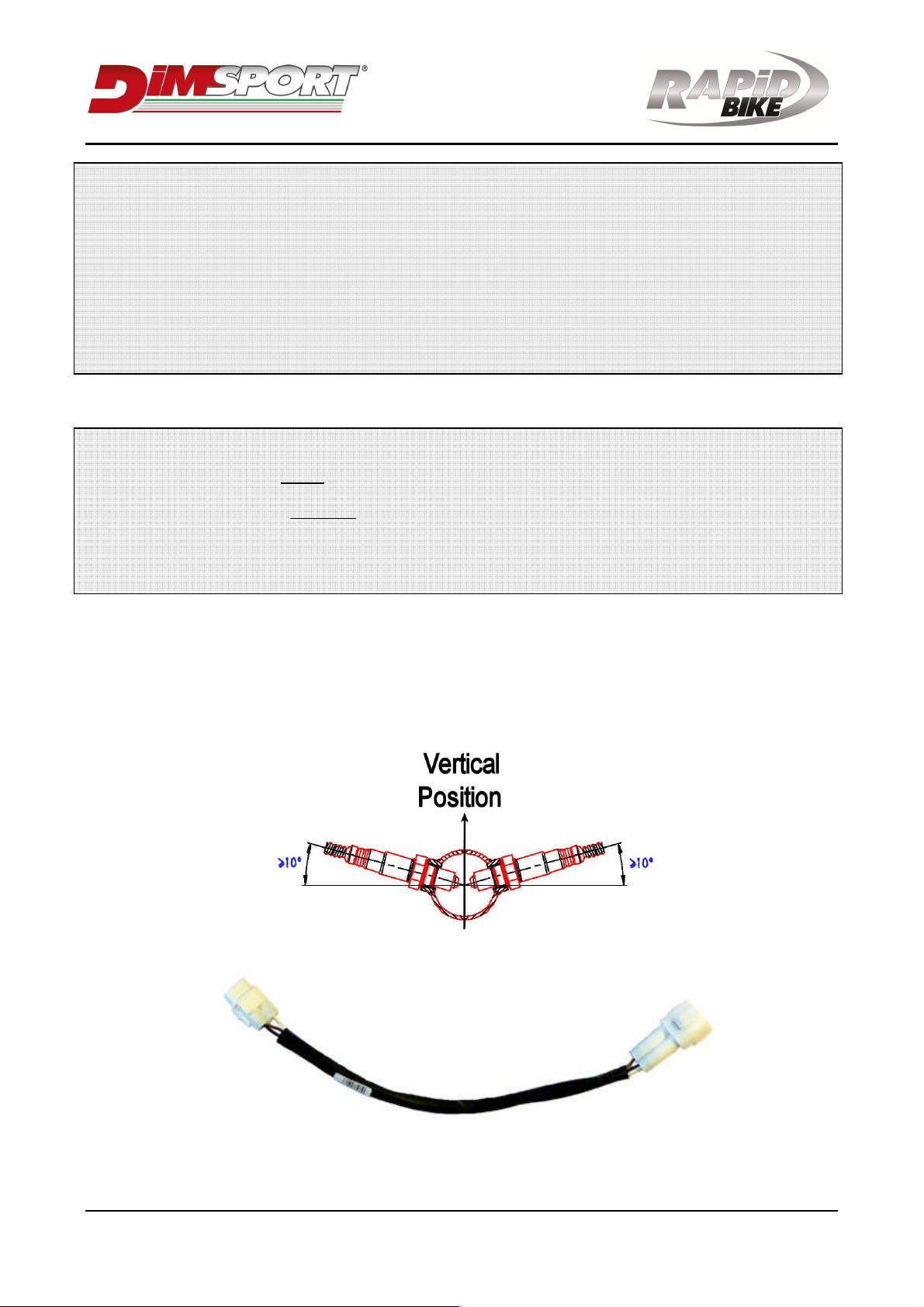
1. Install the M 18x1,5mm steel bung on the exhaust before the catalytic converter (if present) and where
the multiple cylinders collect. If more My Tuning Bike must be installed it’s recommended to install the
bung 15cm from the exhaust port on the respective cylinder you wish to tune.
The bung must be installed in a way that reduces the risk of moisture contamination on the sensor.
We suggest an inclination higher than 10°(see pict ure).
2. Connect the wiring F27-TERM1 to the Rapid Bike connector marked as CAN.
Issued by: PM approved by DG Rev.07 date 12/06/16 pag. 3/6
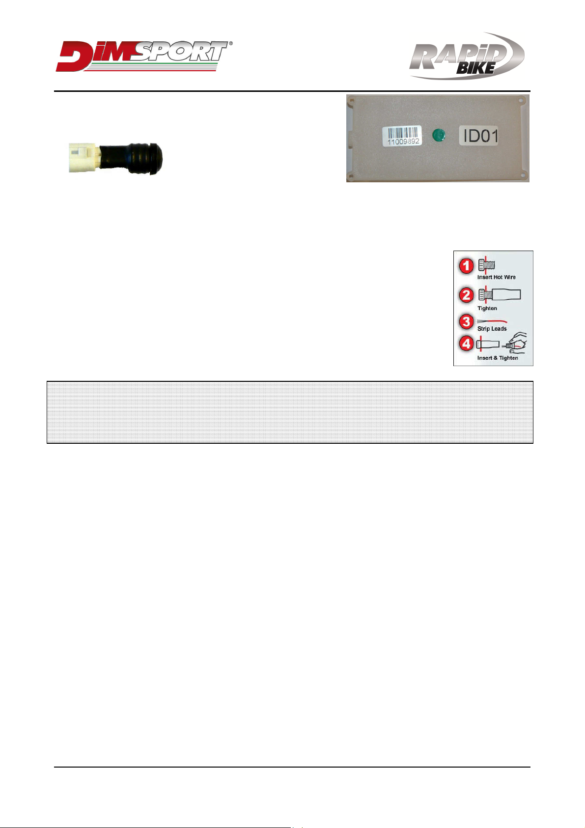
3. Connect the 3 pin connector of the My Tuning Bike labelled
as ID01 to the wiring F27-TERM1.
4. Connect the connector F27-
TERM2 to the 3 pin white
connector of the My Tuning Bike
wiring.
5. Connect the O2 sensor to the My Tuning Bike wiring ensuring the cable will not get pinched or damaged
by the exhaust.
6. Connect the black wire with the eyelet of the My Tuning Bike to the negative pole of the battery.
7. Connect the red wire of the My Tuning Bike to a switched 12v source using the
supplied posi-tap.
My Tuning Bike absorbs maximum 3A (during O2 sensor heating process): check on
the maintenance manual of the vehicle if this power consumption is supported by the
12v source. The power for the tail light is a good location.
8. Close or disable the clean air injection system (also called PAIR valve) if applicable
(only on vehicles WITHOUT catalytic converter).
WARNING
My Tuning Bike will record the serial number of the module to which is connected at the first engine
start. Then it will not work if connected to other modules.
This will happen also when more My Tuning Bike are installed to a Rapid Bike module
Settings
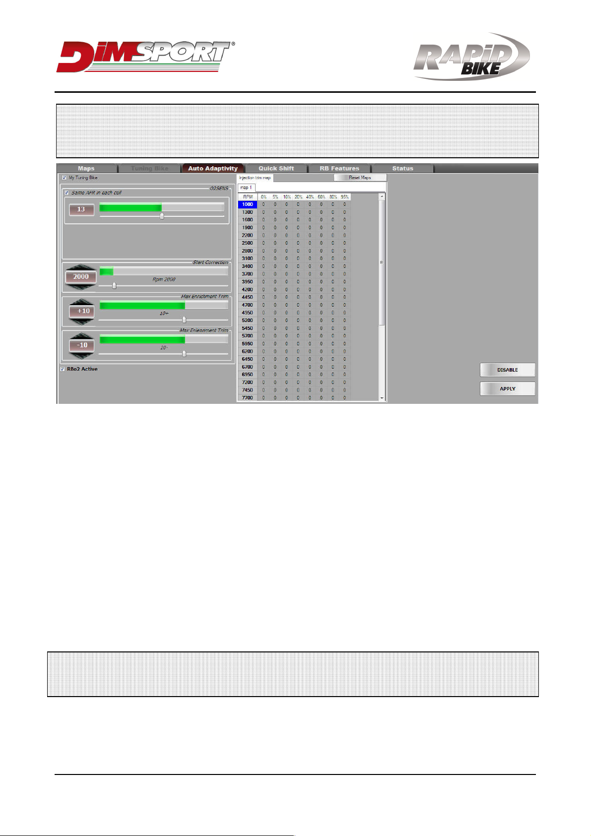
When My Tuning Bike is connected to a Rapid Bike Evo or Racing module it activates automatically with the
default settings:
oTarget AFR: 13.2 for all the cells of the map (except TPS 0%)
oStart correction: 2000 rpm
oMax positive trim: 10
oMax negative trim: 10
A different AFR target for each cell of the map can be set as following:
1. Connect the RapidBike module to the software (downloadable from the RapidBike website) by means of
the USB cable.
2. Select the mask “My Tuning Bike” and remove the mark on the option Same AFR for each cell.
3. Select the cells and modify the AFR value with buttons +and –on the keyboard (or icons in the
software).
Multiple cells can be highlighted by using click/drag with the mouse and modified together: in this situation
the value can be changed with buttons +and – or by right-clicking with the mouse and selecting Edit.
Right-click with the mouse on a cell and select Don’t modify to disable the injection adjustments on that cell.
4. Click on Apply to save new settings.
Issued by: PM approved by DG Rev.07 date 12/06/16 pag. 4/6
WARNING
Disable the feature “Average cell” removing the flag in “RB Features Map configuration
rows\columns”.
If the Rapid Bike module is set for a switch map the adjustments will be only calculated for the map 1.
The switch map will not switch between map 1 and map 2 but it will turn on/off the My Tuning Bike
(position map 1 = ON, position map 2 = OFF)..
If the My Tuning Bike is turned off the injection trim map won’t be modified again but its values will be
used to adjust the base map during driving.
Operating and checks
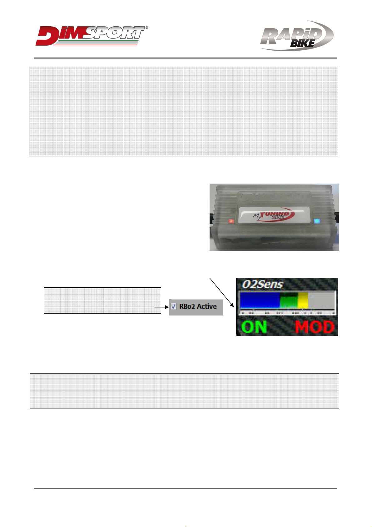
1. Turn on ignition, the blue led and the red led must turn
on:
Blue led => connection established with RB module.
Red led => 12V power supply ok.
2. Turn on the engine, the My Tuning Bike will
automatically start to heat the O2 sensor.
3. Then the Rapid Bike module will wait until three
conditions are satisfied:
a) The My Tuning Bike O2 sensor has reached the operating temperature (the red led starts to flash).
b) If the OEM O2 sensor is installed and it is hot and works properly. The blue sign will appear on the
down side of the AFR display to confirm this condition.
If the OEM O2 sensor is not installed,
deselect the RB-O2 function that is in
Auto-adaptivity.
c) The engine has exceeded 4500 rpm/min.
The purpose is to avoid adjustments while the engine is working in
unstable conditions (engine heating, etc.).
Once the three conditions are satisfied the adjustments will be performed for RPM values higher than the
one set for the option Start correction.
Warning
If the My Tuning Bike is connected to a RapidBike Racing module it is strictly necessary that the RB
wiring is connected properly to the crankshaft position sensor.
4. After the driving session, the injection trim map can be checked by downloading the map from the
RapidBike module and selecting the form My Tuning Bike.
The injection trim map can be erased by clicking on Reset Maps or it can be added permanently to the
base map by right-clicking on a cell and select Add correction (then the trim map will be erased).
If the RapidBike maps are configured with one map for each injector the My Tuning Bike will use only
one trim map that will be applied on each injection map.
Issued by: PM approved by DG Rev.07 date 12/06/16 pag. 5/6
Warning
Multiple trim maps will be created if multiple My Tuning Bike will be connected to the RapidBike
module or if a map for each gear ratio will be set (a trim map for each gear ratio will be created).
My Tuning Bike is equipped with two leds (red and blue) that allows to verify the installation of the device:
-Red led off: device not powered
-Red led on: device powered
-Red led flashing: O2 sensor hot
-Blue led off: CAN line communication off / CAN line communication error
-Blue led flashing: CAN line communication on
Multiple My Tuning Bike connection
System requirements for n°2 My Tuning Bike:
-2 cylinders engine where an O2 sensor for each exhaust port can be installed.
-Rapid Bile Evo or Racing set with one map for each cylinder.
System requirements for n°3 or n°4 My Tuning Bike:
-3 or 4 cylinders engine where an O2 sensor for each exhaust port can be installed.
-RapidBike Evo o Racing set with one map for each injector. If the bike has 8 injectors the trim
map will adjust couples of injectors: 1-5, 2-6, 3-7 and 4-8.
WARNING: when multiple My Tuning Bike are connected, if the map configuration is wrong or there
is a problem on the connection of the devices, only the AFR value of the device ID01 will be used to
trim the injection.
1. Connect the wiring F27-TERM1 between the Rapid Bike wiring 3 pin connector marked as CAN and the
male 3 pin connector of the first My Tuning Bike (ID01).
Others My Tuning Bike must be connected in series to the first My Tuning Bike:

Issued by: PM approved by DG Rev.07 date 12/06/16 pag. 6/6
WARNING: others My Tuning Bike will be identified as ID02, ID03 and ID04. Follow the order when
connecting them in series.
2. Connect the F27-TERM2 connector to the 3 pin female connector of the last My Tuning Bike.
A trim value of the main AFR target can be set for each My Tuning Bike.
The correction maps n°2, 3 and 4 will be displayed on the software only after the first use of the My Tuning
Bike devices (engine on, O2 sensors hot, etc.) because the RapidBike module creates them only after
checking the proper operating and connection of all the devices connected.
Dimsport Srl
Zona Industriale Madonnina - Loc. san Iorio, 8 B
15020 SERRALUNGA DI CREA (AL) - ITALY
T (+39) 0142.9552 F (+39) 0142.940094
E-mail: info.rapidbike@dimsport.it
is a company of
Table of contents
Other DimSport Motorcycle Accessories manuals


Popular Motorcycle Accessories manuals by other brands


hepco & becker
hepco & becker 500102 manual

Saddlemen
Saddlemen T06-09-0291RS User's guide & installation instructions

GYS
GYS Alien True Color XXL manual

hepco & becker
hepco & becker 7009521 00 01 manual

SW-Motech
SW-Motech DUSC M HSK.00.745.10000/B Mounting instructions

Ops-Core
Ops-Core ACH-ARC installation instructions