Dinel CLS-23 User manual

Read carefully the instructions published in this manual before the rst use of the sensor. Keep the manual
at a safe place. The manufacturer reserves the right to implement changes without prior notice
TEHNIČNI LIST IN NAVODILA
KAPACITIVNI MERILNIKI NIVJA - SERIJA: Cls – 23
www.materm.si tel: 02 608 90 10


CONTENT
1 . Safety .........................................................................................................................................4
2 . Packing, transportation and storage ..........................................................................................4
3 . Brief. ...........................................................................................................................................5
4 . Features of variants ...................................................................................................................5
5 . Dimensional drawings ................................................................................................................6
6 . Mounting recommendation .........................................................................................................7
7 . Electrical connection ..................................................................................................................9
8 . Sensor setting ............................................................................................................................11
9 . Status signalization ....................................................................................................................11
10 . Accessories ..............................................................................................................................12
11 . Order code ...............................................................................................................................13
12 . Correct specication examples ................................................................................................13
13 . Safety, protections, compatibility and explosion proof .............................................................14
14 . Use, manipulation and maintenance ........................................................................................14
15 . General conditions and warranty .............................................................................................14
16 . Marking of labels ......................................................................................................................15
17 . Specications ...........................................................................................................................16
CLS–23 © Dinel, s.r.o.
4
All operations described in this instruction manual have to be carried out by trained
personnel or by an accredited person only. Installation, commissioning, operation and
maintenance of the capacitive level sensors has to be carried out in accordance with this
instruction manual; the provisions of regulations in force regarding the installation of
electrical equipment have to be adhered to.
Improper use, installation or set-up of the sensor can lead to crashes in the application,
(overlling of the tank or damage of system components).
The manufacturer is not responsible for improper use, loss of work caused by either
direct or indirect damage, and for expenses incurred at the time of installation or during
the period of use of the level sensors.
1 . Safety
Used symbols
To ensure maximum safety of control processes, we have dened the following safety instructions
and information. Each instruction is labeled with the appropriate pictogram.
Alert, warning, danger
This symbol informs you about particularly important instructions for installation and op-
eration of equipment or dangerous situations that may occur during the installation and
operation. Not observing these instructions may cause disturbance, damage or destruction
of equipment or may cause injury.
Information
This symbol indicates particularly important characteristics of the device.
Note
This symbol indicates helpful additional information.
2 . Packing, transPortation and storage
Equipment CLS–23 is packed in a polythene bag and the whole consignment is placed in a card-
board box. The cardboard box is suitably lled to prevent mechanical damage during transport. Let
the device packed up till the use to prevent possible damage.
Transport to the customer is realized by forwarding company. Upon receipt, please check whether
the shipment is complete and corresponds to the extent of the order, or whether during the transport
did not occurred the damage of the packaging or the equipment. The device apparently damaged
during transport do not use and contact the manufacturer to resolve the situation.
If the device is transported further, then only wrapped in the original packaging and protected
against shocks and weather. Store the device in its original packaging in a dry place, sheltered from
the weather, with humidity up to 85% without the effects of chemically active substances. Storage
temperature range is from -10 °C to +50 °C.
Sensor variants CLS–23_–20 a 21 with the electrodes longer than 100 mm are tted with
protective caps at the ends of the electrodes to prevent damage of the electrodes, box
rupture or injury of handling persons. Before commissioning, remove the caps.

5
© Dinel, s.r.o. CLS–23
4 . FeatUres oF variants
3 . brieF
Capacitive level sensors (switches) CLS–23 are designed for limit level detection of electrically
conductive and non-conductive uids in vessels, reservoirs, sumps, pipes, tanks, etc. The sensitiv-
ity of the sensor can be easily set by placing magnetic pen on sensitive spot.
The process coupling at the housing can be with metric thread (M18x1.5 ; M20x1.5), pipe thread
(G3/8” ; G1/2”) or sealing thread (NPT 1/2–14). Output performances – transistor output with open
collector (PNP), two wire electronic switch (S) and NAMUR output.
There are next performances available: N – Normal for non-explosive areas, E – Extended tem-
perature range for non-explosives areas, Xi – Explosion proof (intrinsically safe for explosive ar-
eas), NT – High temperature variant for non-explosives areas and XiT – High temperature variant
for explosive areas.
CLS–23_–10 Uncoated short bar electrode, for sensing of electrically non-conductive
liquids (mineral and plant oils,resins, etc.). Mounting in horizontal position.
Electrode length 30 mm.
CLS–23_–11 Insulated (coated) short bar electrode, for non-aggressive electrically
conductive liquid sensing (water, water solutions). The insulation is made
from PP (Polypropylene).
Electrode length 30 mm.
CLS–23_–12 Insulated (coated) short bar electrode, for moderately aggressive electri
cally conductive liquid sensing (chemicals, water, moderately aggressive
water solutions). Higher temperature resistance than variant “11”. The insula
tion is made from FEP (Tetrauoroethylene-Peruoro-Propylene).
Electrode length 30 mm
CLS–23_–20 Partly insulated rod electrode, for level detection of conductive and non-
conductive liquids, partially resistant to vapours (water) condensation in the
sensing area. The insulation is made from FEP. Vertical mounting; horizontal
mounting (from the side) is possible for shorter electrodes (up to 200 mm)
Electrode length from 50 mm to 1 m.
CLS–23_–21 Fully insulated rod electrode, for universal use, for level detection of con
ductive liquids (water, water solutions). Resistant to vapours (water) conden
sation in the sensing area and partially resistant to medium
spraying. The insulation is made from FEP. Vertical mounting; horizontal
mounting (from the side) is possible for shorter electrodes (up to 200 mm).
Electrode length from 50 mm to 1 m.
CLS–23_–30 Uncoated removable rod electrode, for level detection of conductive and
non-conductive liquids. Vertical mounting; horizontal mounting (from the
side) is possible for shorter electrodes (up to 200 mm).
Electrode length from 50 mm to 1 m.
CLS–23 © Dinel, s.r.o.
6
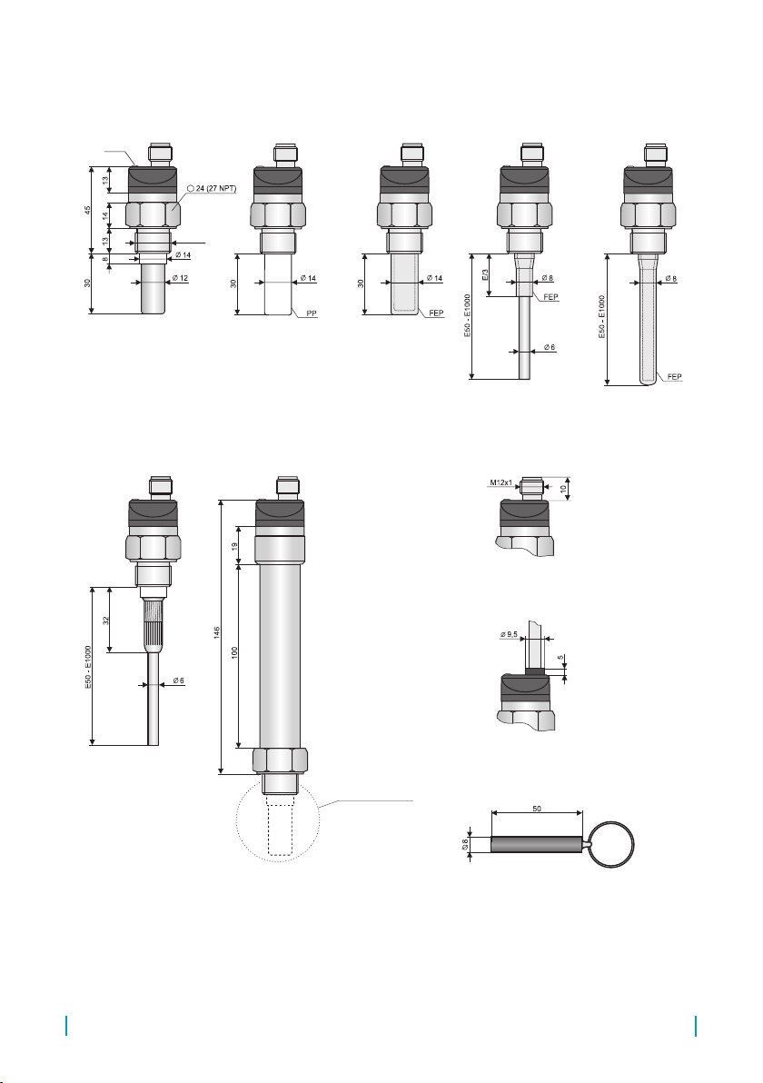
5 . dimensions drawings
CLS – 23_ – 10 CLS – 23_– 11
CLS – 23_ – 30
Variant „A“
with cable outlet
Variant „C“ with connector
(except CLS–23N, NT, Xi, XiT)
Magnetic pen MP–8
Electrode type according
to specic variants
CLS – 23_ –12
CLS – 23_ –21
High temperature variants
(CLS–23_T–10; 12; 20; 21; 30)
CLS – 23_ –20
Thread
Types of threads:
G 3/8''
M18x1,5
M20x1,5
1/2–14 NPT
LED *
* Variant „E“ without LED state indicator

7
© Dinel, s.r.o. CLS–23
6 . moUnting recommendation
CLS-23 level sensors can be xed in a vertical, horizontal or bevelled position into the shell of the
vessel, the storage tank for the xation console in the pit, by screwing into the welding ange, using
a xing nut or NPT process connection.
Basic application recommendations are mentioned below.
During assembly into the metal tank or the storage tank, it is not necessary to separately ground the
base of the level sensor. In the case of installation in concrete tanks or silos, it is recommended to
install a level sensor on the auxiliary metal construction (console, cap, etc.) and to then connect it
using a permanently dipped metal item or with steel reinforcement in the concrete (armouring).
In the case of the reading of an aggressive medium, we recommend that the producer be consulted.
If the sensors are tted with protective caps at the ends of the electrodes, remove the
caps before commissioning.
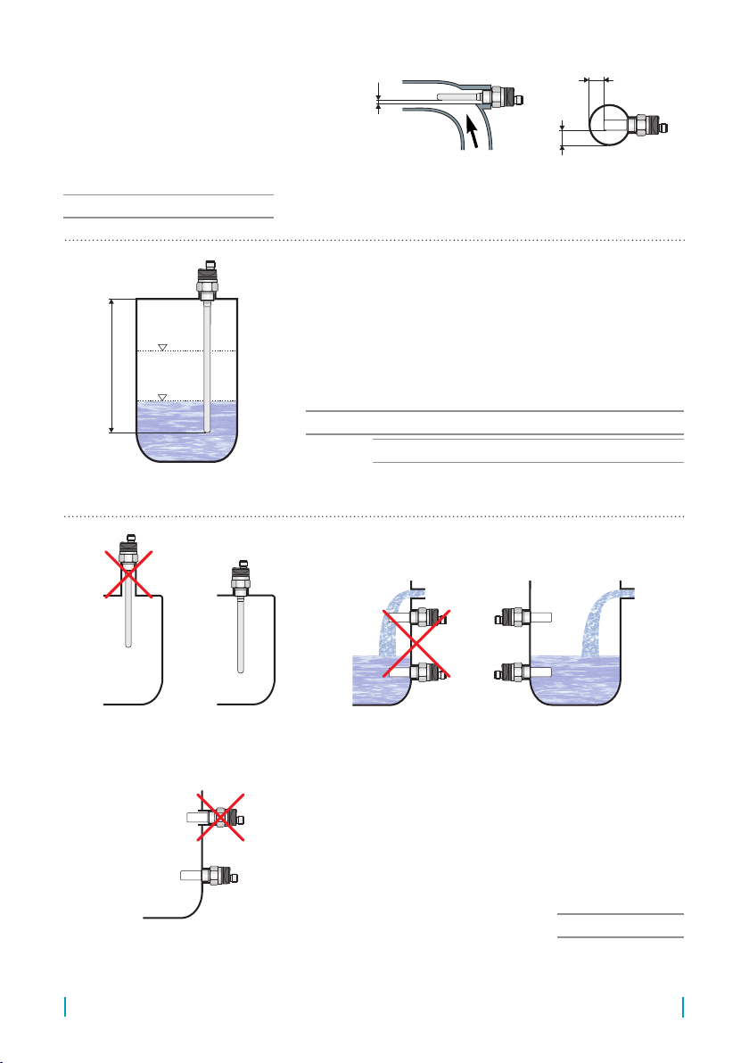
For top mounting (vertical position) it is necessary to keep the
distances from walls and from other sensors.
All vertically mounted sensors
E – Electrode length in mm
max.
min.
E
b
E
E
k
c
d
>5
E
a
Ep
>5
>5
30
E
30a
EEp
20
E
40b
50
E
10c
40
E
40d
20
E
20k
+≈
>
+≥=
+≥=
+≥=
+≥=
30
E
30a
EEp
20
E
40b
50
E
10c
40
E
40d
20
E
20k
+≈
>
+≥=
+≥=
+≥=
+≥=
30
E
30a
EEp
20
E
40b
50
E
10c
40
E
40d
20
E
20k
+≈
>
+≥=
+≥=
+≥=
+≥=
30
E
30a
EEp
20
E
40b
50
E
10c
40
E
40d
20
E
20k
+≈
>
+≥=
+≥=
+≥=
+≥=
Mounting in a bypass measuring tube. We recommend to
keep the tube diameter.
Applies to: CLS–23_–20, 21, 30
E – Electrode length in mm
max.
min.
E
b
E
E
k
c
d
>5
E
a
Ep
>5
>5
Fig. 1: Vertical mounting
Fig. 2: Bypass measuring tube
CLS–23 © Dinel, s.r.o.
8
When installing the sensor into the pipe it
is necessary to choose properly internal di-
ameter of the tube to ensure the inner walls
distances from the electrode to min. 5 mm.
In some cases (sticky liquids, liquids with low
dielectric constant) is suitable to mount the
sensor in the knee tube.
Applies to: CLS–23_–10, 11, 12, 20, 21
When installing the sensor in vertical position it can be used
for 2-state (LO-HI) level control between the min. and max.
level. The position of the minimum and maximum level can be
changed by setting the sensor. Fluid changes require new set-
tings of the sensor
E – Electrode length in mm
Applies to: CLS–23_–20, 30 (only for electrically non-conductive liquids)
Applies to: CLS–23_–21 (for electrically conductive liquids)
max.
min.
E
b
E
E
k
c
d
>5
E
a
Ep
>5
>5
max.
min.
E
b
E
E
k
c
d
>5
E
a
Ep
>5
>5
max.
min.
E
b
E
E
k
c
d
>5
E
a
Ep
>5
>5
Sensor installation close to inlet hole, in a narrow
neck or using improper welding ange may result in
malfunction of the sensor.
Suitable welding anges can be found in the Dinel
assortment, types ON, NN – see Accessories.
Applies to: All variants
max.
min.
E
b
E
E
k
c
d
>5
E
a
Ep
>5
>5
max.
min.
E
b
E
E
k
c
d
>5
E
a
Ep
>5
>5
max.
min.
E
b
E
E
k
c
d
>5
E
a
Ep
>5
>5
max.
min.
E
b
E
E
k
c
d
>5
E
a
Ep
>5
>5
max.
min.
E
b
E
E
k
c
d
>5
E
a
Ep
>5
>5
WRONG CORRECT
WRONG
CORRECT
WRONG CORRECT
Fig. 3: Mounting in the pipe
Fig. 4: Two state regulation by hysteresis setting
Fig. 5: Long tting tubes in side wall mounting

9
© Dinel, s.r.o. CLS–23
Applies to: CLS–23_–20, 21, 30 (for electrode length up to 300 mm)
For electrodes with a length over 300 mm for the detection in non-conductive containers (sensors
in vertical position) must be used the auxiliary electrode (e.g. conductivity probe). The auxiliary
electrode is connected to the sensor housing. Recommended length of the auxiliary electrode
and the distance from the sensor are shown in the picture.
Suitable types of auxiliary electrode probes are e.g. Dinel CNP–18F–30 with M18 thread.
max.
min.
E
b
E
E
k
c
d
>5
E
a
Ep
>5
>5
Electrical connection to
the sensor housing
Conductive probe
CNP–18F–30
Non-conductive tank
30
E
30a
EEp
20
E
40b
50
E
10c
40
E
40d
20
E
20k
+≈
>
+≥=
+≥=
+≥=
+≥=
E – Electrode length in mm
30
E
30a
EEp
20
E
40b
50
E
10c
40
E
40d
20
E
20k
+≈
>
+≥=
+≥=
+≥=
+≥=
max.
min.
E
b
E
E
k
c
d
>5
E
a
Ep
>5
>5
Auxiliary electrode PDE–18
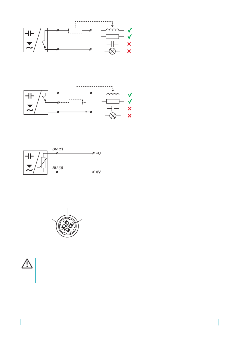
7 . electrical connection
For “A” variant with the xed cable, the individual colour cores of the connecting cable are con-
nected to the respective terminals of the related equipment (supply unit).
For “C” variant with the connector, the cable can be supplied with the sensor (length 2 or 5 m), tted
with the pressed connector socket or dismountable connector socket without the cable (see acces-
sories). In this case the cable is connected to the inside pins of the socket according to Fig. 10.
The sensor with related equipment is interconnected by a suitable three-core (P variation) or two-
core (S and R variations) cable. The length of the cable for the Xi and XiT variations must be
selected with respect to the maximum permitted parameters (usually inductance and capacity) of
the outside intrinsically safe circuit of supply units (NSSU, NDSU, NLCU). If using a dismountable
connector socket, the outside diameter of the cable is a maximum of 6 mm
Sensors CLS–23 are equipped with protection against over-voltages and current overload. The capacity
loads and low resistance (bulb) are evaluated by sensors with output type „P“ and „S“ as short circuit.
Sensors with output type „R“ are designed for interconnect to intrinsically safe supply units.
In case of strong ambient electromagnetic interference, paralleling of conductors with power distribu-
tion, or for the distribution to distance over 30 m, we recommend to use shielded cable.
Fig. 6: Auxiliary electrode in non-conductive tanks
CLS–23 © Dinel, s.r.o.
10
CLS–23_–_–_–S–_
Positive pole (+ U) of power supply
is connected through a load (relay) to
brown (blue) wire or pin connector No.
1, negative pole is connected to white
wire or pin connector No. 3.
Typ CLS–23_–_–_–P–_
Positive pole (+ U) of power supply is
connected to brown wire or pin connec-
tor No. 1, negative pole is connected to
blue wire or pin connector No. 3. Load
(relay) is connected to black wire or pin
connector No. 4.
+U
0V
BN (1)
WH, BU (3)
+U
0V
BN (1)
BU (3)
BK (4)
+U
0V
BN (1)
WH, BU (3)
+U
0V
BN (1)
BU (3)
BK (4)
Typ CLS–23_–_–_–R–_
Brown wire or pin connector No. 1 is
connected to positive pole (+U) of In-
trinsically safe supply unit. Blue wire or
pin.connector No. 3 is connected to
negative pole of Intrinsically safe sup-
ply unit.
Electrical connection must be done in de-energized state! For switching supply sources,
it is necessary to check that the input is galvanically separated from the network side
and that they are tted with a lter suppressing the conforming interference (terminals
+ and – oscillate together towards the ground potential), or the interference is removed
in another manner.
Fig. 7: “S“ type sensors connection
(2 - wire electronic switch)
Fig. 8: “P“ (PNP) type sensors connection
Fig. 9: “R“ (NAMUR) type sensors connection
Legend:
(1...3) – Terminals number for variants with connector
BN – Brown
WH – White
BK – Black
BU – Blue
Fig. 10: Inside of the connector socket
Output (BK)
0V (BU)
+U (BN)

11
© Dinel, s.r.o. CLS–23
8 . sensor settings
The setting is done by placing magnetic pen MP–8 to sensitive
spot Mlocated on the front of the sensor. Short time attaching
(up to 2 sec.) of the magnetic pen to the sensitive spot M
makes the sensor open. Long time attaching (at least 4 sec.) of
the pen when the level is changed, denes closed state of the
sensor. In this way is set the sensitivity for the measured medi-
um and switching modes SO (normally open) or SC (normally
closed).
Sensitive spot
FACTORY DEFAULT SETTINGS:
Types CLS–23_–10; –20; –30 are set to detect mineral oil, CLS–23_–11; –12; –21 to detect water.
The mode O is set (sensor closes when immersed).
When the level is low (the container is empty), attach the magnetic pen
MP–8 to the sensitive spot
M
for long time (min. 4 sec.). When the level
is high (the container is full), attach the magnetic pen MP–8 to the sensitive
spot
M
for short time (max. 2 sec.).
.
When the level is low (the container is empty), attach the magnetic pen
MP–8 to the sensitive spot M for short time (max. 2 sec.). When the
level is high (the container is full), attach the magnetic pen MP–8 to the
sensitive spot M for long time (min. 4 sec.).
mode O
(normally open)
mode C
(normally close)
9 . statUs signalization (only with LED state indicator variant)
Indicator Function
Orange LED
Continuous light – Sensor is closed (switched ON)
Dark – Sensor is open (switched OFF)
Rapid ashing (period 0.2 s) – Unrecognized upper and lower limits or setting mistake
Slow ashing (period 0.8 s) – Short circuit at sensor output
Sensors of type CLS–23E are produced without signaling indicator LED. For control of correct
settings it is necessary to interconnect the sensor to related evaluation unit or load.
In the case of the vertical mounting for detection of non-conductive liquids by sensors CLS–23_–20;
–30 and for detection of conductive and non-conductive liquids by sensors CLS–23_–21 it neces-
sary to set limits ON and OFF when electrode of the sensor is immersed to medium.
CLS–23 © Dinel, s.r.o.
12
For security reasons, we recommend to set the mode O (normally open, sensor closes when immersed)
for minimum level detection. Any failure of the sensor or wiring is equally apparent as the emergency
level state. Analogously – for the maximum level detection is recommended to set the mode C (normally
closed, sensor opens when immersed).
10 . accessories
Standard
(included in the level sensors price)
• 1pc of Magnetic pen MP–8
• 1pc of Seal (non-asbestos)
Optional
(for extra charge)
• Extra cables (over the standard length 2 m)
• Non-rewirable connector plug M12
(“N” and “NT” variants)
• Rewirable connector plug M12
(“N” and “NT” variants)
• Steel or Stainless steel welding ange
• Stainless steal xing nut UM–18x1,5
• Other seals (PTFE, Al, etc.)
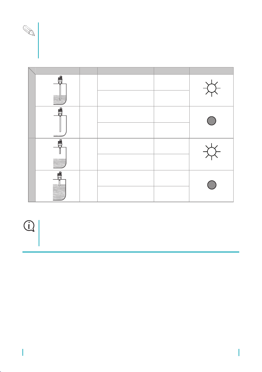
Level state Mode Type of sensor Output state LED indicator *
Minimum level sensing
O
CLS–23_–_ _– _ –P–_
CLS–23_–_ _– _ –S–_ CLOSED
(Shine)
CLS–23Xi–_ _– _ –R–_
CLS–23XiT–_ _– _ –R–_
HIGHER
CURRENT
O
CLS–23_–_ _– _ –P–_
CLS–23_–_ _– _ –S–_ OPEN
(Dark)
CLS–23Xi–_ _– _ –R–_
CLS–23XiT–_ _– _ –R–_
LOWER
CURRENT
Maximum level sensing
C
CLS–23_–_ _– _ –P–_
CLS–23_–_ _– _ –S–_ CLOSED
(svítí)
CLS–23Xi–_ _– _ –R–_
CLS–23XiT–_ _– _ –R–_
HIGHER
CURRENT
C
CLS–23_–_ _– _ –P–_
CLS–23_–_ _– _ –S–_ OPEN
(nesvítí)
CLS–23Xi–_ _– _ –R–_
CLS–23XiT–_ _– _ –R–_
LOWER
CURRENT
* Variant „E“ without LED state indicator
Sensor for each ash of the LED switches its output on for approx. 3 ms. This period is sufciently
short to avoid unwanted switching of relay contacts. For binary inputs, we recommend to set the
lter so as not to respond to pulses shorter than 3 ms.
Units Dinel NSSU, NDSU a NLCU with transistor switch („T“) detects and transmitts these pulses
to the output.
13
© Dinel, s.r.o. CLS–23
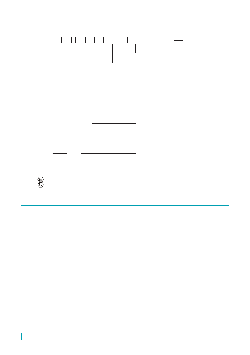
11 . order code
CLS – 23 – – – – E Cable
Performance:
N – Normal for non-explosive areas
E – Extended temperature range variants for non-explosive
areas (without LED)
NT – High temperature variants for non-explosive areas
Xi – (intrinsically safe) for hazardous areas
XiT – (intrinsically safe), high temperature variants
Process connection:
G3/8 – Pipe thread G 3/8“
G1/2 – Pipe thread G 1/2“
M18 – Metric thread M 18x1,5
M20 – Metric thread M 20x1,5
NPT – Sealing thread 1/2–14 NPT
Output type:
P – PNP (Open collector)
S– 2-wire electronic switch
R – NAMUR (For Xi variants only)
Electric connection:
A – Cable outlet (+ Spec. the length of the cable)
C – Connector – (+ Spec. type of the socket)
except variant “A“
Type and electrode performance:
10 – Uncoated short bar, length 30 mm
11 – Insulated (coated) short bar (PP), length 30 mm
12 – Insulated (coated) short bar (FEP), length 30 mm
20 – Partly insulated rod (FEP), length 50 ... 1000 mm
21 – Fully insulated rod (FEP), length 50 ... 1000 mm
30 – Uncoated removable rod, length 50 ... 1000 mm
Length of cable in meters
(variant “A“)
Electrode length in mm
12 . correct sPeciFication examPles
CLS–23N–10–A–S–G3/8 cable 5 m
(N) For non-explosive areas; (10) Uncoated short bar electrode 30 mm, (A) Cable outlet with 5 m xed cable; (S) 2-wire electronic
switch; (G3/8) Process connection with pipe thread G3/8”
CLS–23E–30–A–S–G1/2 E450 cable 10 m
(E) Extended temperature range performance for non-explosive areas; (30) Uncoated removable rod electrode; (A) Cable outlet with
10 m xed cable; (S) 2-wire electronic switch; (G1/2) Process connection with pipe thread G1/2”; (E450) Electrode length 450 mm.
CLS–23NT–20–C–S–M18 E320
(NT) High temperature variants for non-explosive areas; (20) Partly insulated rod electrode (FEP); (C) Electrically connection with
connector; (S) 2-wire electronic switch; (M18) Process connection with metric thread M18x1.5; (E320) Electrode length 320 mm.
CLS–23Xi–11–C–R–NPT
(Xi) Intrinsically safe for hazardous areas; (11) Insulated (coated) short bar (PP) electrode 30 mm (C) Electrically connection with
connector; (R) NAMUR output type; (NPT) Process connection with sealing thread 1/2 – 14 NPT.

CLS–23 © Dinel, s.r.o.
14
It is forbidden to make any changes or interventions to the CLS–23 sensor without the
consent of the producer. Any repairs must only be carried out by the producer or author-
ized service organisations.
Assembly, installation, commissioning, service and maintenance of the CLS–23 level
sensor must be carried out in accordance with this manual and the provisions of valid
standards for the installation of electrical equipment must be complied with.
14 . Use, maniPUlation and maintenance
The level meter does not require any personnel for its operation.
13 . saFety, Protections, comPatibility and exPlosion ProoF
The level sensor is equipped with a protection against electric shock on electrode, polarity, overvoltage
and short-term current overload on the output.
Electromagnetic compatibility is provided by conformity with standards EN 55011 / B, EN 61326-1, EN
61000-4-2 (8 kV), -4-3 (10 V/m), -4-4 (2 kV), -4-5 (1 kV) a -4-6 (10 V).
Explosion proof CLS–23Xi and XiT is examined FTZÚ - AO210 Ostrava - Radvanice, certicate No.
FTZÚ 12 ATEX 0106X.
Supplied electrical equipment matches the requirements of valid European directives for safety and
electromagnetic compatibility. The declaration of Conformity for the above mentioned product was
issued.
Special conditions for safe use
If the apparatus is used as device of Group II and with using of an approved power supply device,
which output parameters comply with required input parameters, it is necessary to have an galvanic
separation or in case of apparatus without galvanic separation (Zener barriers) it is necessary to
provide equipotential equalizing between sensor and barrier earthing point.
Design CLS–23Xi-11 (12, 20, 21) can be used in zone 0. Other design DLS–23Xi can be used in
zone 0 only electrode part and head with electronics can be used only in zone 1.
Ambient temperature: Tamb = - 20°C ... +75°C
Temperature of measured medium according to design variant:
Xi typ 10, 12: (- 25°C to + 105°C)
Xi typ 11: (- 10°C to + 105°C)
Xi typ 20, 21, 30, XiT: (- 30°C to + 150°C)
15 . general conditions and warranty
Dinel, s.r.o. guarantees for the period of three (3) years that the product has the characteristic as in
technical specication is mentioned. The guarantee can be invoked only when the product is com-
pleted by original invoice and guarantee list. This guarantee does not cover the damages resulting
from misuse, improper installation or incorrect maintenance.

15
© Dinel, s.r.o. CLS–23
16 . marking oF labels
This guarantee cease when user or the other person makes any changes on the product or the
product is mechanically or chemically damaged, or the serial number is not readable.
In the case of rightful complaint we replace the product or its defective part.
Real label size 81 x 9 mm.
CLS-23Xi-__-_-R-____ E____ No.:______
IP68
Štítek pro CLS-23Xi-10(30)-
FTZÚ 12 ATEX 0106X
U = 12V I = 15m A
P = 45mW C = 15nF
L = 10uH t = -20 .. . +75 °C
a
i
i
i
i
II 1/2G Ex ia IIC T6 Ga/Gb
i
CLS-23XiT-__-_-R-____ E____ No.:______
IP68
Štítek pro CLS-23XiT-10(30)-
FTZÚ 12 ATEX 0106X
U = 12V I = 15m A
P = 45mW C = 15nF
L = 10uH t = -20 .. . +75 °C
i
i
i
i
II 1/2G Ex ia IIC T6 Ga/Gb
i
CLS-23Xi-__-_-R-____ E____ No.:______
IP68
Štítek pro CLS-23Xi-11(12, 20, 21)-
FTZÚ 12 ATEX 0106X
U = 12V I = 15m A
P = 45mW C = 15nF
L = 10uH t = -20 .. . +75 °C
i
i
i
i
II 1G Ex ia IIB T6 Ga
i
CLS-23XiT-__-_-R-____ E____ No.:______
IP68
Štítek pro CLS-23XiT-11(12, 20, 21)-
FTZÚ 12 ATEX 0106X
U = 12V I = 15m A
P = 45mW C = 15nF
L = 10uH t = -20 .. . +75 °C
i
i
i
i
II 1/2G Ex ia IIB T6 Ga/Gb
i
a
a
a
1026
1026
1026
1026
Symbol of producer: Dinel logo®
Internet address: www.dinel.cz
Level sensor type and electrode length: CLS–23Xi(XiT)–_ _–_–R–_ _ Exxxx
Serial number: Ser. No.: xxxxx – (from the left: production year, serial production No.)
Label of non-explosive device: , Performance II 1/2G Ex ia IIC T6 Ga/Gb
Limit operating parameters: Ui = 12 V =, Ii = 15 mA; Pi = 45 mW; Ci = 15 nF; Li = 10 μH
Ambient temperature range: ta= -20 ... +75 °C
Number of certicate of intrinsically safety: FTZÚ 12 ATEX 0106X
Compliance mark:
Protection class: IP68, Electro-waste take-back system mark:
Level sensor label data CLS–23Xi(T)–10, 30
Symbol of producer: Dinel logo®
Internet address: www.dinel.cz
Level sensor type and electrode length: CLS–23Xi(XiT)–_ _–_–R–_ _ Exxxx
Serial number: Ser. No.: xxxxx – (from the left: production year, serial production No.)
Label of non-explosive device: , Performance II 1G Ex ia IIB T6 Ga or II 1/2G Ex ia IIB T6 Ga/Gb
Limit operating parameters: Ui = 12 V =, Ii = 15 mA; Pi = 45 mW; Ci = 15 nF; Li = 10 μH
Ambient temperature range: ta= -20 ... +75 °C
Number of certicate of intrinsically safety: FTZÚ 12 ATEX 0106X
Compliance mark:
Protection class: IP68, Electro-waste take-back system mark:
Level sensor label data CLS–23Xi(T)–11, 12, 20, 21
CLS-23Xi-__-_-R-____ E____ No.:______
IP68
Štítek pro CLS-23Xi-10(30)-
FTZÚ 12 ATEX 0106X
U = 12V I = 15m A
P = 45mW C = 15nF
L = 10uH t = -20 .. . +75 °C
a
i
i
i
i
II 1/2G Ex ia IIC T6 Ga/Gb
i
CLS-23XiT-__-_-R-____ E____ No.:______
IP68
Štítek pro CLS-23XiT-10(30)-
FTZÚ 12 ATEX 0106X
U = 12V I = 15m A
P = 45mW C = 15nF
L = 10uH t = -20 .. . +75 °C
i
i
i
i
II 1/2G Ex ia IIC T6 Ga/Gb
i
CLS-23Xi-__-_-R-____ E____ No.:______
IP68
Štítek pro CLS-23Xi-11(12, 20, 21)-
FTZÚ 12 ATEX 0106X
U = 12V I = 15m A
P = 45mW C = 15nF
L = 10uH t = -20 .. . +75 °C
i
i
i
i
II 1G Ex ia IIB T6 Ga
i
CLS-23XiT-__-_-R-____ E____ No.:______
IP68
Štítek pro CLS-23XiT-11(12, 20, 21)-
FTZÚ 12 ATEX 0106X
U = 12V I = 15m A
P = 45mW C = 15nF
L = 10uH t = -20 .. . +75 °C
i
i
i
i
II 1/2G Ex ia IIB T6 Ga/Gb
i
a
a
a
1026
1026
1026
1026
CLS-23Xi-__-_-R-____ E____ No.:______
IP68
Štítek pro CLS-23Xi-10(30)-
FTZÚ 12 ATEX 0106X
U = 12V I = 15m A
P = 45mW C = 15nF
L = 10uH t = -20 .. . +75 °C
a
i
i
i
i
II 1/2G Ex ia IIC T6 Ga/Gb
i
CLS-23XiT-__-_-R-____ E____ No.:______
IP68
Štítek pro CLS-23XiT-10(30)-
FTZÚ 12 ATEX 0106X
U = 12V I = 15m A
P = 45mW C = 15nF
L = 10uH t = -20 .. . +75 °C
i
i
i
i
II 1/2G Ex ia IIC T6 Ga/Gb
i
CLS-23Xi-__-_-R-____ E____ No.:______
IP68
Štítek pro CLS-23Xi-11(12, 20, 21)-
FTZÚ 12 ATEX 0106X
U = 12V I = 15m A
P = 45mW C = 15nF
L = 10uH t = -20 .. . +75 °C
i
i
i
i
II 1G Ex ia IIB T6 Ga
i
CLS-23XiT-__-_-R-____ E____ No.:______
IP68
Štítek pro CLS-23XiT-11(12, 20, 21)-
FTZÚ 12 ATEX 0106X
U = 12V I = 15m A
P = 45mW C = 15nF
L = 10uH t = -20 .. . +75 °C
i
i
i
i
II 1/2G Ex ia IIB T6 Ga/Gb
i
a
a
a
1026
1026
1026
1026

CLS–23 © Dinel, s.r.o.
16
17 . sPeciFications
technical sPeciFications
Supply voltage 6 ... 30 V DC
Supply current – Output type P
– Output type S
max. 0,6 / 7 mA (OFF / ON state)
max. 0,6 mA (OFF state)
Switched current (Min. / Max.) – Output type P
– Output type S
max. 100 mA
3,3 mA / 40 mA (min. / max.)
Remanent voltage - ON state – Output type P
– Output type S
1,8 V
6,0 V
Output time delay 0,1 s
Protection class IP68 (0,1 MPa)
Cable
(for cable outlet performance)
CLS–23N, NT, Xi, XiT
CLS–23E
PVC 2x 0,34 mm2 (3x 0,34 mm2 – výstup type P)
Silicone 2x 0,5 mm2
Weight
(with 2 m cable and 30 mm electrode)
CLS–23N, E, Xi
CLS–23NT, XiT
Approx. 45 g
Approx. 190 g
electrical Parameters – variants Xi, XiT
Supply voltage 8 ... 9 V DC
Current supply (state OFF / ON) – NAMUR ≤ 1 mA / ≥ 2,2 mA
Max. internal values Ui = 12 V DC; Ii = 15 mA; Pi = 45 mW; Ci = 15 nF; Li = 10 µH
Coupling capacity / Electric strength 44 nF / 250 V AC
Cable LC parameters Typical C < 150 pF/m
Typical L < 0,8 µH /m
Process connection
Type Size Marking
Metric thread M18 x 1,5 M18
Metric thread M20 x 1,5 M20
Pipe thread (BSP) G 3/8'' G3/8
Pipe thread (BSP) G 1/2'' G1/2
Sealing thread 1/2–14 NPT
oUtPUt tyPe
Output Variants
S („S“) N, E, NT
PNP („P“) N, E, NT
NAMUR („R“) Xi, XiT
material PerFormance
Sensor part Variants Material
Housing All variants Plastic PP
Process coupling All variants Stainless steel W.Nr. 1.4305 (AISI 303)
Electrode All variants Stainless steel W.Nr. 1.4305 (AISI 303)
Electrode insulation CLS–23_–11 Plastic PP
Electrode insulation CLS–23_–12, 20, 21 Plastic FEP

17
© Dinel, s.r.o. CLS–23
oUtPUt tyPe
Output Variants
S („S“) N, E, NT
PNP („P“) N, E, NT
NAMUR („R“) Xi, XiT
working areas (EN 60079-10–1)
CLS – 23N
Performance for non-explosive areas
CLS – 23E
Extended temperature performance for non-explosive areas
CLS – 23NT
High temperature performance for non-explosive areas
CLS – 23Xi (XiT)–10
CLS–23Xi (XiT)–30
Performance for explosive areas (XiT–high temperature), II 1/2 G Ex ia IIC T6 Ga/
Gb
with intrinsically safe supply units, electrode part zone 0, housing
zone 1
CLS – 23Xi–11, 12, 20, 21 Performance for explosive areas, II 1 G Ex ia IIB T6 Ga with intrinsically safe
supply units, whole sensor zone 0
CLS – 23XiT–11, 12, 20, 21
High temperature performance for explosive areas,
II 1/2 G Ex ia IIB T6 Ga/Gb
with intrinsically safe supply units, electrode part zone 0, housing zone 1.
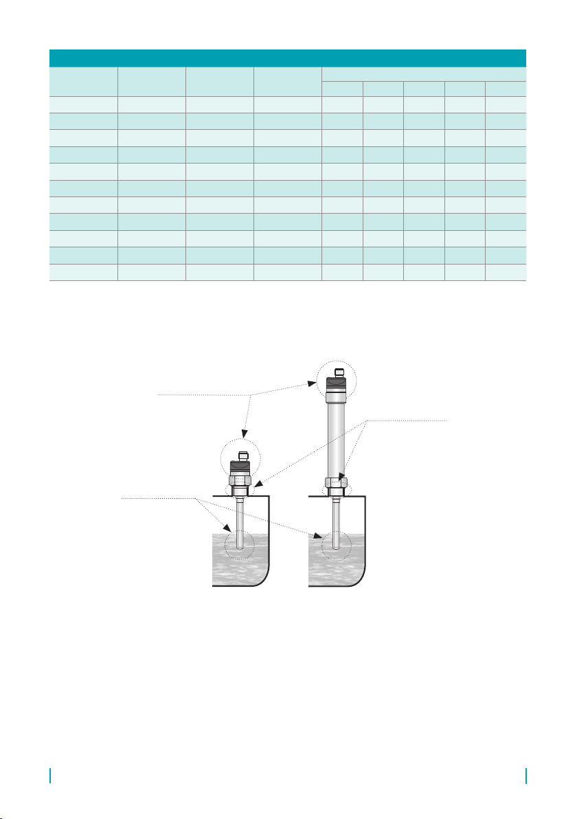
temPeratUre and PressUre resistance – variants N, E, NT
Variant
(Performance) Temperature tpTemperature tmTemperature taMax. operating pressure for temperature tp
to 30°C to 85°C to 105°C to 130°C do 150°C
CLS–23N–10 -25°C ... +105°C -25°C ... +105°C -20°C ... +80°C 8 MPa 6 MPa 5 MPa – –
CLS–23E–10 -25°C ... +120°C -25°C ... +120°C -25°C ... +105°C 8 MPa 6 MPa 5 MPa – –
CLS–23NT–10 -30°C ... +150°C -30°C ... +150°C -20°C ... +80°C 8 MPa 6 MPa 5 MPa 4 MPa 3 MPa
CLS–23N–11 -10°C ... +105°C -10°C ... +105°C -10°C ... +80°C 7 MPa 5 MPa 4 MPa – –
CLS–23E–11 -10°C ... +105°C -10°C ... +105°C -10°C ... +105°C 7 MPa 5 MPa 4 MPa – –
CLS–23N–12 -25°C ... +105°C -25°C ... +105°C -20°C ... +80°C 8 MPa 6 MPa 5 MPa – –
CLS–23E–12 -25°C ... +120°C -25°C ... +120°C -25°C ... +105°C 8 MPa 6 MPa 5 MPa – –
CLS–23NT–12 -30°C ... +150°C -30°C ... +150°C -20°C ... +80°C 8 MPa 6 MPa 5 MPa 4 MPa 3 MPa
CLS–23N–20 -25°C ... +105°C -30°C ... +150°C * -20°C ... +80°C 3 MPa 2,5 MPa 2 MPa – –
CLS–23E–20 -25°C ... +120°C -30°C ... +150°C * -25°C ... +105°C 3 MPa 2,5 MPa 2 MPa – –
CLS–23NT–20 -30°C ... +150°C -30°C ... +150°C -20°C ... +80°C 3 MPa 2,5 MPa 2 MPa 1,5 MPa 1 MPa
CLS–23N–21 -25°C ... +105°C -30°C ... +150°C * -20°C ... +80°C 3 MPa 2,5 MPa 2 MPa – –
CLS–23E–21 -25°C ... +120°C -30°C ... +150°C * -25°C ... +105°C 3 MPa 2,5 MPa 2 MPa – –
CLS–23NT–21 -30°C ... +150°C -30°C ... +150°C -20°C ... +80°C 3 MPa 2,5 MPa 2 MPa 1,5 MPa 1 MPa
CLS–23N–30 -25°C ... +105°C -30°C ... +150°C * -20°C ... +80°C 8 MPa 6 MPa 5 MPa – –
CLS–23E–30 -25°C ... +120°C -30°C ... +150°C * -25°C ... +105°C 8 MPa 6 MPa 5 MPa – –
CLS–23NT–30 -30°C ... +150°C -30°C ... +150°C -20°C ... +80°C 8 MPa 6 MPa 5 MPa 4 MPa 3 MPa
* Valid for top mounting (in vertical position)
CLS–23 © Dinel, s.r.o.
18
temPeratUre and PressUre resistance – variants Xi, XiT
Variant
(Performance) Temperature tpTemperature tmTemperature taMax. operating pressure for temperature tp
to 30°C to 85°C to 105°C to 130°C to 150°C
CLS–23Xi–10 -25°C ... +105°C -25°C ... +105°C -20°C ... +75°C 8 MPa 6 MPa 5 MPa – –
CLS–23XiT–10 -30°C ... +150°C -30°C ... +150°C -20°C ... +75°C 8 MPa 6 MPa 5 MPa 4 MPa 3 MPa
CLS–23Xi–11 -10°C ... +105°C -10°C ... +105°C -10°C ... +75°C 7 MPa 5 MPa 4 MPa – –
CLS–23Xi–12 -25°C ... +105°C -25°C ... +105°C -20°C ... +75°C 8 MPa 6 MPa 5 MPa – –
CLS–23XiT–12 -30°C ... +150°C -30°C ... +150°C -20°C ... +75°C 8 MPa 6 MPa 5 MPa 4 MPa 3 MPa
CLS–23Xi–20 -25°C ... +105°C -30°C ... +150°C * -20°C ... +75°C 3 MPa 2,5 MPa 2 MPa – –
CLS–23XiT–20 -30°C ... +150°C -30°C ... +150°C -20°C ... +75°C 3 MPa 2,5 MPa 2 MPa 1,5 MPa 1 MPa
CLS–23Xi–21 -25°C ... +105°C -30°C ... +150°C * -20°C ... +75°C 3 MPa 2,5 MPa 2 MPa – –
CLS–23XiT–21 -30°C ... +150°C -30°C ... +150°C -20°C ... +75°C 3 MPa 2,5 MPa 2 MPa 1,5 MPa 1 MPa
CLS–23Xi–30 -25°C ... +105°C -30°C ... +150°C * -20°C ... +75°C 8 MPa 6 MPa 5 MPa – –
CLS–23XiT–30 -30°C ... +150°C -30°C ... +150°C -20°C ... +75°C 8 MPa 6 MPa 5 MPa 4 MPa 3 MPa
* Valid for top mounting (in vertical position)
tm– Medium
operating temp
tp– Temp. in process
connection place
ta–
Ambient temperature
range (on housing)
Variants:
N; E; Xi;
Variants:
NT; XiT;

Materm d.o.o.
2313 Fram
Tel.: 02 608 90 10
Fax: 02 608 90 18
E-mail: i[email protected]
www.materm.si
The latest version of this instruction manual can be found at www.materm.si
Version:
industrial electronics
10/2013
Other manuals for CLS-23
2
Table of contents
Other Dinel Accessories manuals


Popular Accessories manuals by other brands


ROSE DISPLAYS
ROSE DISPLAYS ANOQUICK SQUARE WITH GOTCHA AND MULTICLIPS manual

Joolz
Joolz footboard instruction manual

SilentCall
SilentCall MEDALLION DB2-MC Installation and operating instructions

SAFEasy
SAFEasy SF2 Series instruction manual

Panasonic
Panasonic Grid-EYE AMG88 Series manual

ETC
ETC Unison Echo E-OCC-SR installation guide


