Dinel DLS-27 Series User manual

Read carefully the instructions published in this manual before the rst use of the level meter. Keep the manual
at a safe place. The manufacturer reserves the right to implement changes without prior notice.
průmyslová elektronika

1 . Basic description ..................................................................................................................... 3
2 . Variants of sensors .................................................................................................................. 4
3 . Dimensional drawing ................................................................................................................ 5
5 . Mechanical mounting ............................................................................................................... 6
4 . Installation and putting into operation ...................................................................................... 6
6 . Range of application and installation of individual variants ...................................................... 12
7 . Electrical connection ................................................................................................................ 13
8 . Settings .................................................................................................................................... 15
9 . Function and status indication .................................................................................................. 16
10 . Order code ............................................................................................................................. 17
11 . Correct specication examples .............................................................................................. 17
12 . Accessories ............................................................................................................................ 18
13 . Safety, protections, compatibility and explosion proof ........................................................... 18
14 . Use, manipulation and maintenance ...................................................................................... 19
15 . General, conditions and warranty .......................................................................................... 20
16 . Marking of labels .................................................................................................................... 20
17. Technical specications.......................................................................................................... 23
18 . Packings, shipping and storage ............................................................................................. 26
19 . FAQ (Frequently asked questions) ........................................................................................ 27

DLS–27 © Dinel, s.r.o.
3
Capacitive level sensors DLS® are designed for limit sensing of the level of liquid and bulk
solids in tanks, sumps, tubes or, hoppers, silos, etc. The sensors are manufactured in several
modications of sensing electrodes (rod and rope). The electrodes can be given an insulating
coating, a useful feature in case of adhesive, aggressive or conductive media sensing. Rod
electrodes are also available in a version with reference tube for measuring uids in tanks made
from non-conductive material.
Sensors are manufactured in the following congurations: N – for non-explosive areas, Xd –
For use in ammable dust atmospheres; Xi – Explosion proof – intrinsically safe for hazardous
(explosive) areas and XiM – Explosion proof – intrinsically safe for use in mines with methane
or ammable dust presence danger (see technical specications). There are high temperature
performance NT, XiT, XiMT available and various types of process connection (metric and pipe
thread, jointless connection Tri-clamp).
To ensure maximum safety of control processes, we have dened the following safety instructions
and information. Each instruction is labelled with the appropriate pictogram.
This symbol informs you about particularly important instructions for installation and operation of
equipment or dangerous situations that may occur during the installation and operation. Not observing
these instructions may cause disturbance, damage or destruction of equipment or may cause injury.
This symbol indicates particularly important characteristics of the device.
This symbol indicates helpful additional information.
Alloperationsdescribed in this instructionmanualhave to becarriedout by trained personnel
or by an accredited person only. Warranty and post warranty service must be exclusively
carried out by the manufacturer.
Improper use, installation or set-up of the sensor can lead to crashes in the application.
The manufacturer is not responsible for improper use, loss of work caused by either direct
or indirect damage, and for expenses incurred at the time of installation or during the period
of use of the level sensors.

4
© Dinel, s.r.o. DLS–27
• DLS–27_–10 Uncoated short bar electrode for sensing non-adhesive bulk solids (sand,
sugar) and non-conductive liquids (petroleum products, oils), horizontal
mounting.
Electrode length 50 mm or 100 mm.
• DLS–27_–11 Fully coated short bar electrode, for sensing conductive liquids (water).
Horizontal mounting into tanks and tubes.
Electrode length 30 mm.
• DLS–27_–20 Semi-coated rod electrode for sensing slightly adhesive bulk solids
(cement, our) and non-conductive liquids (plant oils), horizontal, slant or
vertical mounting.
Electrode length from 0.1 m to 1 m.
• DLS–27_–21 Fully coated rod electrode (FEP insulation) for sensing conductive liquids
(water solutions, water), adhesive and aggressive materials, horizontal or ver-
tical mounting.
Electrode length from 0.1 m to 1 m.
• DLS–27_–22 Fully coated rod electrode (PFA insulation) with enhanced resistance,
for sensing aggressive conductive liquids and materials. Horizontal or vertical
mounting.
Electrode length from 0,1 m ... 1 m.
• DLS–27_–30 Dismountable uncoated rod electrode for sensing bulk solids and conduc-
tive or non-conductive liquids. Vertical or horizontal slant mounting.
Electrode length 0.1 m ... 3 m.
• DLS–27_–31 Fully coated rod electrode, for sensing aggressive conductive liquids (water,
various chemicals). Vertical mounting.
Electrode length from 0.1 m to 2 m.
• DLS–27_–40 Uncoated rope electrode and weight, for general purpose use in deeper
silos (bulk solids sensing – sand, gravel, cement) or sumps (sensing liquids).
Vertical mounting.
Electrode length from 1 m to 6 m.

DLS–27 © Dinel, s.r.o.
5
DLS – 27_ – 10 DLS – 27_ – 11 DLS – 27_ – 20 DLS – 27_ – 21, 22 DLS – 27_ – 30
DLS – 27_ – 31 DLS – 27_ – 40 High tempera-
tures variants
Tri-clamp
thread *
* Type of threads: G 3/4''
M27x2
M30x1,5
connection **
** connection:
Tri-Clamp CI34 (ø 34 mm)
6
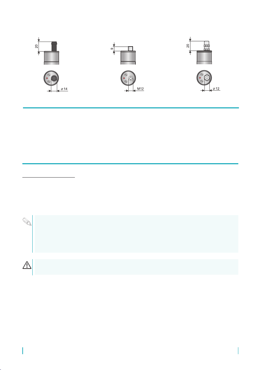
© Dinel, s.r.o. DLS–27
Variants “C” with
connector
Variants “D” with
cable outlets
Variants “B” with cable
outlets
• DLS® level sensors can be xed in a vertical, horizontal or slanted position into the wall of
a vessel, storage tank or on a xation console in a sump by screwing into the welding ange,
using a xing nut or TriClamp® process connection.
• Basic application recommendations are mentioned below.
During assembly into the metal tank or the storage tank, it is not necessary to separately ground
the base of the level sensor. In case of installation in concrete sumps or silos, it is appropriate to
install the level sensor onto a metallic auxiliary construction (console, lid, etc.), and then connect to
ametallic, constantly submergedobject,or withsteelwith steelreinforcementsin concrete (armouring).
In the case of the reading of an aggressive medium, we recommend that the producer be consulted
If the sensors are tted with protective caps at the ends of the electrodes, remove the caps
before commissioning.
Please follow next 3 steps:

DLS–27 © Dinel, s.r.o.
7
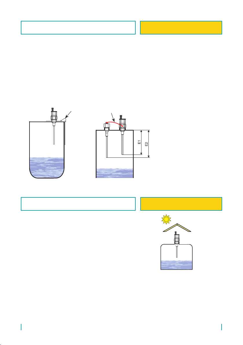
Fig. 1: Vertical mounting
In case of vertical mounting, sensors can be mounted
into open, closed and pressurized tanks. The stated dis-
tances relate to the electrode length (longer electrode).
mm20050h
E
3
2
m
E
4
3
p
E
3
4
s
E
3
1
E
10
1
a
20
E
40b
50
E
10c
40
E
40d
20
E
20k
mm20050h
E
3
2
m
E
4
3
p
E
3
4
s
E
3
1
E
10
1
a
20
E
40b
50
E
10c
40
E
40d
20
E
20k
mm20050h
E
3
2
m
E
4
3
p
E
3
4
s
E
3
1
E
10
1
a
20
E
40b
50
E
10c
40
E
40d
20
E
20k
E– Electrode length in mm
In case of side wall mounting (Fig.
3), place the sensor outside the ow
of bulk solids or liquids.
Fig. 3: Correct and incorrect installation
into storage tank side wall
In the case of side wall mounting. it
is necessary to avoid long tting tubes,
where sensed medium could accumulate
(g. on right). We recommend mounting
the sensor so that the whole sensing elec-
trode and insulation is inside the storage
tank (Figure 2 – on left).
Fig. 2: Correct and incorrect installation
with a long tube
VERTICAL MOUNTING FOR TYPE: All vertically mounted
sensors
CORRECT AND INCORRECT INSTALLATION
WITH A LONG TUBE
FOR TYPE: All from side mounted
sensors
CORRECT AND INCORRECT INSTALLATION
INTO STORAGE TANK SIDE WALL
FOR TYPE: All side mounted sen-
sors

8
© Dinel, s.r.o. DLS–27
mm20050h
E
3
2
m
E
4
3
p
E
3
4
s
E
3
1
E
10
1
a
20
E
40b
50
E
10c
40
E
40d
20
E
20k
mm20050h
E
3
2
m
E
4
3
p
E
3
4
s
E
3
1
E
10
1
a
20
E
40b
50
E
10c
40
E
40d
20
E
20k
mm20050h
E
3
2
m
E
4
3
p
E
3
4
s
E
3
1
E
10
1
a
20
E
40b
50
E
10c
40
E
40d
20
E
20k
Protective roof cover is recommended to
prevent mechanical damage of the sensor
electrode when vertical movement of ma-
terial could damage the sensing electrode
(abrasive materials, bulk-solid materials
forming blocks, piece goods).
Fig. 4: Protective roof mounting
E– Electrode length in mm
In the case of slant wall mounting it is necessary to eliminate tting tubes, thereby reducing
medium sedimentation. The wrong example of mounting is shown in Figure 5 on the left. The ap-
propriate mounting on the auxiliary vertical plate is shown in the middle. In some cases the variant
is allowed as shown in Fig. 5 on the right. But this is recommended only for measuring bulk-solid
materials by a sensor of the DLS–27_–10 type, which do not mechanically damage the electrode
and do not form separate blocks.
DLS–27_–10
!
Fig. 5: Slant wall mounting
In case of vertical installation for sensing
the level of unknown (conductive and non-
conductive) liquids in tanks or sumps, it is
appropriate to bend the electrode into a right
angle. This will increase the local sensitivity
and accuracy of sensing the level at the spot
of the bend.
When weather conditions (wind, rain, snow)
clearly inuence the electrode (open sumps),
we recommend using types with an insulated
electrode (DLS-27_-21, 31).
h = 50 to 200 mm
Fig. 6: Bending of the electrode end to sense
unknown uids
PROTECTIVE ROOF MOUNTING FOR TYPE: DLS–27_–10 and DLS–
27_–20
SLANT WALL MOUNTING FOR TYPE: DLS–27_–10 and DLS–
27_–20
BENDING OF THE ELECTRODE END TO SENSE
UNKNOWN FLUIDS FOR TYPE: DLS–27_–30
DLS–27 © Dinel, s.r.o.
9
max.
min.
E
a
b
k
d
m
p
s
E
h
> 5
E1
E
E
c
E2
Conductive probe
CNP–18
Electrically connect
Auxiliary plate
electrode PDE-27
E2 = E1+50
E1, E2 – Electrode length in mm
Fig. 7: Auxiliary electrode in non-conductive tanks
In the case of the application of the sensor in an electrically non-conductive (e.g. plastic) vessel
in the vertical position, then for the correct function, it is recommended to connect the housing of
the level sensor with an auxiliary electrode. The auxiliary electrode can consist of a bar which is
permanently dipped into the medium (e.g. conductive probe CNP–18), or can be use the auxiliary
plate electrode (PDE-27), where the rst part has thread for install of the sensor and the second part
is installed from the side on the wall into the area for the expected switching of the level sensor. Both
parts of PDE-27 are connected by steel wire. The area of the plate auxiliary electrode is a minimum
200 cm2. For non-conductive liquids, the only variation possible is with the plate auxiliary electrode
and in this case it is necessary to place the level sensor to prevent the movement of electrodes and
the axis is at the distance of lmax = E1/10, lmin = 20 mm.
The level meter must not be installed in locations exposed
to direct solar radiation and must be protected against
the eects of weather. In the event that installation in a
location with direct solar radiation is unavoidable, it is
necessary to install a shielding cover above the level
meter.
Fig. 8: Solar radiation shielding cover
AUXILIARY ELECTRODE IN NON-CONDUCTIVE
TANKS
FOR TYPE: DLS–27_–20, 21, 22,
30, 31
SOLAR RADIATION SHIELDING COVER FOR TYPE: All type
10
© Dinel, s.r.o. DLS–27
Cable
PVC hose
Hose clip
Fig. 10: Protective hose install
mm20050h
E
3
2
m
E
4
3
p
E
3
4
s
E
3
1
E
10
1
a
20
E
40b
50
E
10c
40
E
40d
20
E
20k
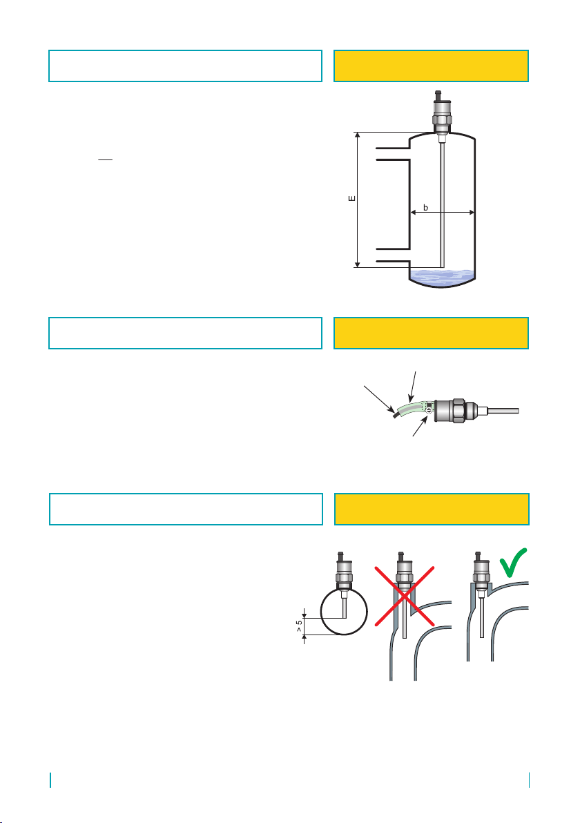
Mounting in a bypass measuring tube. We rec-
ommend upholding the tube diameter.
E– Electrode length in mm
Fig. 9: Bypass measuring tube
In the case of mounting in the pipe it is nec-
essary to provide the minimum distance of the
inner walls from the electrode at 5 mm. In some
cases (sticky liquids, low permittivity liquids) it
is better to mount the sensor into a pipe bend.
Fig. 11: Sensor mounting in a tube
If the sensor is placed vertically in an outdoor
environment or in the event of increased mechanical
stress, it is recommended to install a 15/10 mm PVC
protective hose on the "B" cable.
BYPASS MEASURING TUBE FOR TYPE: DLS–27_–20, 21, 22,
30, 31
PROTECTIVE HOSE INSTALL FOR TYPE: All sensors with cable
outlets
SENSOR MOUNTING IN A TUBE FOR TYPE: DLS–27_–10, 11, 21, 22

DLS–27 © Dinel, s.r.o.
11
In the case of vertical mounting it is possible
to use hysteresis setting for simple two state
regulation (pump control). The height of the
controlled level is done by sensitivity setting, the
gap between the min. and max. is dened by
hysteresis.
E– Electrode length in mm
In the case of vertical mounting especially on
existing tanks, it is necessary to select the pipe
length as short as possible to avoid vapour con-
densation, or sedimentation of impurities. A simi-
lar situation occurs when the sensing electrode
goes through the concrete ceiling of the silo. The
hole diameter should be at least 50 mm (based on
ceiling thickness).
Fig. 12: Two-state level regulation by
hysteresis setting
Fig. 13: Long tting tubes in vertical mounting
mm20050h
E
3
2
m
E
4
3
p
E
3
4
s
E
3
1
E
10
1
a
20
E
40b
50
E
10c
40
E
40d
20
E
20k
÷=
≈
≈
≈
÷≈
+≥=
+≥=
+≥=
+≥=
TWO-STATE LEVEL REGULATION BY HYSTER-
ESIS SETTING
FOR TYPE: DLS–27_–20, 21, 22,
30, 31
LONG FITTING TUBES IN VERTICAL MOUNT-
ING
FOR TYPE: All vertically mounted
sensors
12
© Dinel, s.r.o. DLS–27
Produced in two versions – with 50 mm or 100 mm electrode. The shorter version (E50) is suitable
for clean non-conductive liquids level sensing (oils, diesel, petrol, etc.). The longer version (E100) is
designed for non-adhesive bulk solids or non-adhesive powder materials (plastic granulates, sand,
sugar, grains, detergents, etc.) and other slightly impure, non-conductive liquids (lubricants, plant oils).
The sensor is specied to be mounted directly into a vessel or storage tank wall (best by horizontal
position) by means of welding anges or stainless steel xing nuts. In case of level sensing of low-
permittivity media in non-metal storage tanks, we recommend mounting the sensor on an auxiliary
metal-plate electrode with min. area of 200 cm2.
Specied for level sensing of conductive liquids (water and water solutions). It can be used to identify
the boundary between uids with diering permittivity (e.g. water – oil). The sensor is mounted directly
into the side wall of the vessel or in a pipe (horizontal position) by means of a standard steel or
stainless steel welding ange.
Designed for limit level detection of bulk solids with low specic weight and permittivity (cement,
hydrated lime, our), and for materials expected to have changing properties (y ash, sawdust, feed
mixtures, etc.). It is possible to use it for sensing non-conductive liquids containing a small amount of
water (up to 2%) or other impurities (plant oils, liquid propane, etc.). The sensor is mounted directly
into the wall of a vessel or storage tank using steel welding anges or xing nuts horizontally, slanted
from the side or vertically. It is recommended to mount a sensor with an electrode longer than 300
mm only in the vertical position. Hollow spaces should be minimized between the electrode and the
wall where the sensed material can accumulate (see application notes). In non-metal storage tanks,
we recommend mounting the sensor on an auxiliary metal-plate electrode with min. area of 400 cm2.
Specied for conductive liquids level sensing (water, water solutions, mud, etc.). It reacts to partial
or full immersion of the electrode (depending on the adjusted sensitivity). The lower the sensitivity,
the higher the sensor’s resistance to contaminants and clinging remnants of material. The sensor
with electrode length of up to 200 mm can be desensitized to complete water immersion, so it can be
operated in the horizontal position. The sensor can be operated in the vertical position with any length
up to 1 m. The sensor is mounted directly into the wall of the tank in horizontal or vertical position by
applying a steel or stainless steel welding ange. For variant “22”, the material PFA is used to insulate
the electrode.
Designed for sensing conductive and non-conductive liquids and bulk solids. It is not recommended
to install the sensor into closed vessels (storage tanks) where intensive water vapour condensation
occurs. The sensor reacts to electrically conductive liquids just by touch of the end of electrode.
To react to a non-conductive liquid (bulk solid), it is necessary to have 5 ÷ 20% immersion of the
electrode according to the sensor’s adjusted sensitivity and permittivity of the sensed material. The
sensor is mounted directly into a tank, hopper or sump in slant or vertical position by means of weld-
ing ange or stainless steel xing nut. In non-metal storage tanks, we recommend mounting the
sensor on an auxiliary metal-plate electrode with min. area of 500 cm2.

DLS–27 © Dinel, s.r.o.
13
Designed for limit level detection of conductive liquids (water and solutions of various chemicals).
It is possible to place the sensor electrode into closed vessels (storage tanks), open canals and
sumps. The sensor reacts to the conductive uid level after 2 ÷ 20% immersion of the electrode based
on the sensor’s set sensitivity. The sensor is mounted vertically directly into a vessel, tank or open
(concrete, plastic) sumps by means of welding anges or xing nuts. When installing the sensor into
open sumps, it is necessary to secure conductive connection of the sensor housing with the sensed
liquid. It is possible to use a metal structure, armouring or another auxiliary electrode. If you must
sense an aggressive medium in a closed plastic container, contact the manufacturer.
For sensing conductive and non-conductive liquids and bulk solids at greater depths (sewerage
sumps, shafts, wells, cement storage tanks, sand, gravel, etc.). It is not appropriate to place the
sensor electrode into closed containers (storage tanks) where intensive condensation of water vapour
occurs. The sensor reacts to electrically conductive liquids just by touch of the end of electrode.
To react to non-conductive liquid or bulk solid, a 5 ÷ 20% immersion into the material is necessary
based on the sensitivity set on the sensor and the permittivity of the sensed material. The sensor is
mounted vertically directly into the wall of a storage tank or sump. For open (concrete) sumps, it can
be mounted on an auxiliary metal structure conductively connected with the sensed material. For
mounting, you can use supplied welding anges or xing nuts..
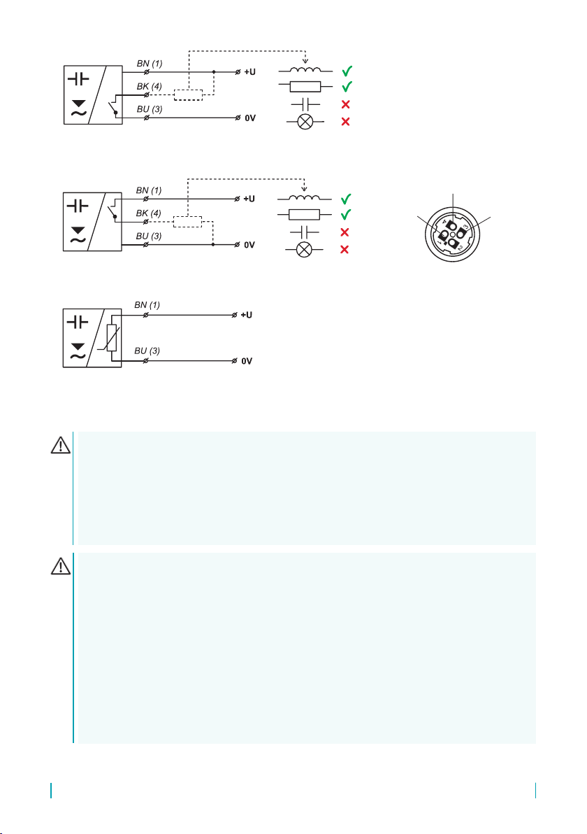
Sensor with NPN or PNP output is allowed to lead only by resistive or inductive lead. Positive
supply voltage (+U) is connected to the brown conductor BN (1), negative (0 V) to the blue
conductor BU (3) and the leads (only NPN or PNP type of output) to the black conductor BK (4).
The capacity loads and low resistance loads (bulb) is evaluated by the sensor as short circuit.
Version Xd is manufacture only with xing cable (variants “D” with cable outlets). The end of this
cable must be in terminal box with protection class IP6x.
For “B” and “D” variants with the xed cable, the individual colour cores of the connecting cable
are connected to the respective terminals of the related equipment (supply unit) see Fig. 14 to 16.
For “C” variant with the connector, the cable can be supplied with the sensor (length 2 or 5 m),
tted with the pressed connector socket or dismountable connector socket without the cable (see
accessories), the connector is not part of the sensor. In this case the cable is connected to the
inside pins of the socket according to Fig. 17.
The sensor with related equipment is interconnected by a suitable three-core (N and Xd variations)
or two-core (Xi, XiT, XiM, XiMT variations) cable. The length of the cable for the Xi, XiT, XiM,
XiMT variations must be selected with respect to the maximum permitted parameters (usually
inductance and capacity) of the outside intrinsically safe circuit of supply units (NSSU, NDSU,
NLCU).
If using a dismountable connector socket, the outside diameter of the cable is a maximum of
6 mm.
14
© Dinel, s.r.o. DLS–27
Electrical connection can only be made when de-energized!
The source of the power voltage must comprise of a stabilised safe low power source with
galvanic separation. In the event that a switch-mode power supply is used, it is essential
that its construction effectively suppresses common mode interference on the secondary
side. In the event that the switch-mode power supply is equipped with a PE safety terminal,
it must be unconditionally grounded! Spark-safe devices type DLS–27Xi(XiT, XiM, XiMT) must
be powered from a spark-safe power source meeting the above-mentioned requirements.
Legend:
(1,...) – numbers of terminals inside
the connector socket
BK – Black
BN – Brown
BU – Blue
output (BK)
0V (BU)
+U (BN)
Fig. 14: NPN output type sensor connection
(conguration N, NT, Xd)
Fig. 15: PNP output type sensor connection
(conguration N, NT, Xd)
Fig. 16: Connection of a sensor with a NAMUR
type output (conguration Xi, XiM, XiT, XiMT)
Fig. 17: Inside of the connector
socket
Due to the possible occurrence of an electrostatic charge on the non-conductive parts of
the sensor, it is necessary to ground all sensors intended for use in environments with an
explosionhazard DLS–27Xi(XiT,XiM, XiMT) andDLS-27Xd. This canbeperformed bygrounding
el. conductive tanks or el. conductive tank lids, and in the case of el. non-conductive tanks
using and grounding an auxiliary plate electrode PDE-27.
In the event that the level meter (sensor) is installed in an outdoor environment at a distance
greater than 20 m from the outdoor switchboard, or from an enclosed building, it is necessary
to supplement the electrical cable leading to the level meter (sensor) with suitable overvoltage
protection.
In the event of strong ambient electromagnetic interference, paralleling of conductors with
power distribution, or for distribution to distances over 30 m, we recommend using a shielded
cable and grounding the shielding on the side of the power source.
DLS–27 © Dinel, s.r.o.
15
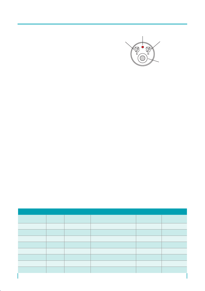
The sensitivity and hysteresis of the level sensor
are set by trimmers “S” and “H” located under the
left cover screw on the rear side.
The basic sensitivity and hysteresis is factory
adjusted and is suitable for most applications.
The sensitivity is set by trimmer “S” located under
the left cover screw on the rear side. Clockwise
turning makes the sensitivity lower, reverse
direction turning makes the sensitivity higher.
If the sensed medium is at your disposal before
setting into service it is useful to provide individual
setting as follows. In this way it is possible to achieve resistance against sediments.
1. The sensor is activated by immersion (by pouring, by ooding) the whole electrode or its part
into the sensed media. By activating the sensor changes its status (LED lights up or goes out).
2. Reduce the sensitivity (by turning the trimmer "S" to the right) until the sensor just stops
responding to this activation (immersion in the media). The LED indication is now in the same
state as before activation.
3. From this point, turn the "S" trimmer 0.5 to 1 turn (depending on the type and length of the
electrode) to the left. The sensor changes the status again and reacts to the activation (ooding)
again.
4. Verify the function by a re-activation of the sensor and watch the sensor behavior.
If the medium is not available in advance, it is possible to use the basic setting from the producer
and after some time of operation (after sedimentation of dirt) to make any correction. However,
it is always necessary to know what the permittivity of the material is and to adapt the setting on
the sensor. In the “Sensitivity characteristics” table it is stated for each type, where the change
of capacity corresponds to the 1 rotation. A denite guide can be the fact that the ooding of the
electrode in the length of 100 mm into the material with relative permeability Ɛr = 2 will cause a
change in the capacity about 1.5 to 2 pF (according to the type of electrode).
The hysteresis (position of the minimum and maximum level) can be changed by turning trimmer
“H” located under the right cover screw on the rear side. Clockwise turning makes the hysteresis
higher, reverse direction turning makes it lower. The lower the hysteresis is, the higher sensitivity is
possible to obtain, but the resistance against various disturbances get worse. For usual applications
is optimal hysteresis from ¼ to ¾ rotation of sensitivity trimmer.
After setting, it is necessary to properly tighten cover screws.
LED
Hysteresis
Cable outlet
or connector
Fig. 18: Top view of level sensor
Sensitivity
Type of sensor Treshold
sensitivity Hysteresis Sensitivity adjusting range Temperature
stability
Rel. permittivity
of material
DLS–27_–10 0,1 pF 0,1 pF ... 2 pF min. 8 pF (1 ot. = 1 pF) ± 0,004 pF/K min. 1,4
DLS–27_–11 0,2 pF 0,2 pF ... 4 pF min. 20 pF (1 ot. = 2 pF) ± 0,007 pF/K min. 5,0
DLS–27_–20 0,1 pF 0,2 pF ... 3 pF min. 15 pF (1 ot. = 1,5 pF) ± 0,006 pF/K min. 1,3
DLS–27_–21 0,3 pF 0,3 pF ... 6 pF min. 30 pF (1 ot. = 3 pF) ± 0,01 pF/K min. 4,0
DLS–27_–22 0,3 pF 0,3 pF ... 6 pF min. 30 pF (1 ot. = 3 pF) ± 0,01 pF/K min. 4,0
DLS–27_–30 0,2 pF 0,2 pF ... 4 pF min. 20 pF (1 ot. = 2 pF) ± 0,01 pF/K min. 1,6
DLS–27_–31 0,3 pF 0,2 pF ... 5 pF min. 25 pF (1 ot. = 2,5 pF) ± 0,01 pF/K min. 5,0
DLS–27_–40 0,3 pF 0,2 pF ... 6 pF min. 20 pF (1 ot. = 2 pF) ± 0,01 pF/K min. 2,0
16
© Dinel, s.r.o. DLS–27
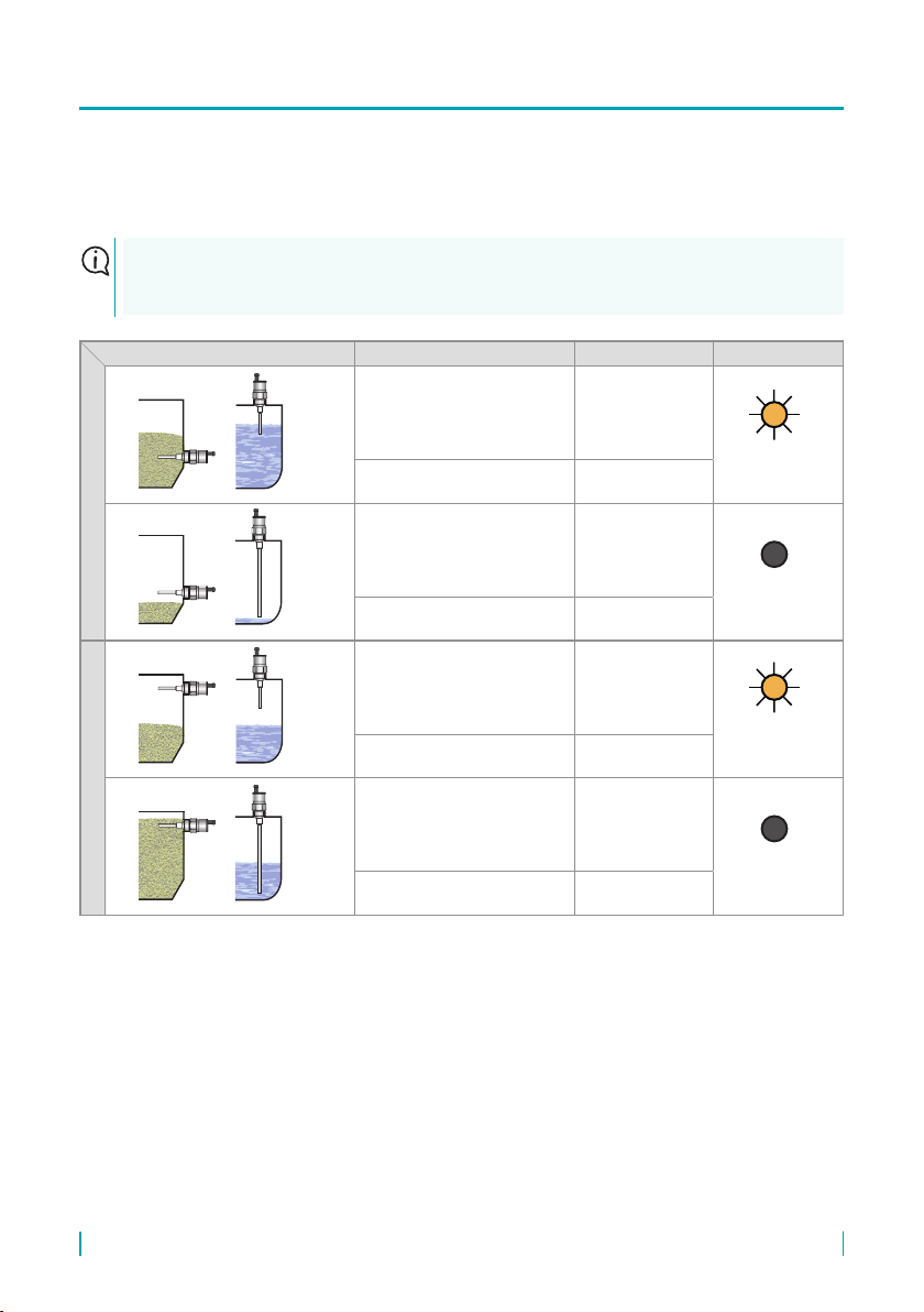
In the following table are the types of inputs and the respective statuses (ON/ OFF) in the case of
a maximum and minimum level sensing. The signalling of the status of the sensor is indicated by
the red LED located on the upper area of the sensor beside the setting trimmers of the hysteresis
(“H”) and the sensitivity (“S”).
For minimum level sensing we recommend sensor with normally open output – NO, PO, RO. It is
for failure safety reasons – eventual failure of sensor behaves similarly as an exceeding of the limit
state.Analogically for maximum level sensing we recommend normally closed outputs – NC, PC, RC.
Level state Type of output Output state LED
Minimum level sensing
DLS–27N_–_ _– _ –NO–_
DLS–27Xd –_ _–D–NO–_
DLS–27N_–_ _– _ –PO–_
DLS–27Xd –_ _–D–PO–_
CLOSED
(Shine)
DLS–27Xi–_ _– _ –RO–_ HIGHER
CURRENT
DLS–27N_–_ _– _ –NO–_
DLS–27Xd –_ _–D–NO–_
DLS–27N_–_ _– _ –PO–_
DLS–27Xd –_ _–D–PO–_
OPEN
(Dark)
DLS–27Xi–_ _– _ –RO–_ LOWER
CURRENT
Maximum level sensing
DLS–27N_–_ _– _ –NC–_
DLS–27Xd –_ _–D–NC–_
DLS–27N_–_ _– _ –PC–_
DLS–27Xd –_ _–D–PC–_
CLOSED
(Shine)
DLS–27Xi–_ _– _ –RC–_ HIGHER
CURRENT
DLS–27N_–_ _– _ –NC–_
DLS–27Xd –_ _–D–NC–_
DLS–27N_–_ _– _ –PC–_
DLS–27Xd –_ _–D–PC–_
OPEN
(Dark)
DLS–27Xi–_ _– _ –RC–_ LOWER
CURRENT

DLS–27 © Dinel, s.r.o.
17
DLS–27N–10–B–NO–M27 E100 cable 5 m
(N) Normal performance; (10) Uncoated bar electrode; (B) Cable outlet with 5 m length cable; (NO) Output type NPN with
open state at non-activated electrode; (M27) Metric thread M27x2 process connection; (E100) Electrode length 100 mm
DLS–27NT–21–C–PC–G E580
(NT) High temperature performance; (21) Fully coated rod electrode (FEP); (C) Connector; (PC) Output type NPN with
closed state at non-activated electrode; (G) Pipe thread G3/4" process connection; (E580) Electrode length 580 mm.
DLS–27Xi–30–C–RO–M30 E1420
(Xi) Explosion-proof performance; (30) Dismountable uncoated electrode; (C) Connector, (RO) Output type NAMUR
with lower current at non-activated electrode, (M30) Metric thread M30x1.5 process connection; (E1420) Electrode
length 1420 mm.
DLS–27Xd–20–D–NC–G E430 cable 3 m
(Xd) Flammable dust areas performance; (20) Partly coated electrode; (D) Cable outlet; (NC) Output type PNP with
closed state at non-activated electrode; (M30) Metric thread M30x1,5 process connection; (E430) Electrode length
430 mm.
process connection:
type of output: N – NPN (open collector)
P – PNP (open collector)
R – NAMUR (change in supply current)
connection method: B – cable outlet (+ cable length)
C – connector (socket not included with
sensor, recommended type - see ac-
cessories.)
D – cable outlet (+ cable length)
type and performance of electrode:
mech. performance:
N – non-explosive areas
NT – high temperature performance
Xd – use in ammable dusts areas
(only var. “D”) only for type 10, 20, 30, 40
Xi – for explosive environments
XiM – for mining environments
XiT – high-temperature conf. for explosive environments
XiMT – high-temperature conf. for mining environments
10 – short bar, uncoated, lengths 50 or 100 mm
11 – short bar, fully coated, xed length 30 mm
20 – rod, partly coated, lengths 0.1 ... 1 m
21 – rod, coated (FEP), length 0.1 ... 1 m
22 – rod, coated (PFA), length 0.1 ... 1 m
30 – rod, uncoated coated, length 0,1 ... 3 m
31 – rod, coated (FEP), length 0,1 ... 2 m
40 – rope with weight, uncoated, length 1 ... 6 m
G– pipe thread G 3/4"
M27 – metric thread M 27x2
M30 – metric thread M 30x1,5
Cl34 – Tri-clamp (ø34 mm)
DLS – 27 – – – – E
electrode length in mm
cable – cable length in m
Output state at non activated electrode:
O – open (NAMUR – Lower current))
C – closed (NAMUR – Higher current)

18
© Dinel, s.r.o. DLS–27
optional – for a surcharge
(see catalogue sheet of accessories)
• Extra cables (over the standard length 2 m)
• Connector socket (type ELWIKA or ELKA)
• Normal steel welding ange ON –27x2
• Stainless steel welding ange NN–G3/4“
• Stainless steel xing nut UM–27x2
• Other seals (PTFE, Al, etc.)
• Auxiliary plate electrode PDE-27
standard – included in the level
sensor price
• 1 pcs. Seal (asbestos free) *
• 1 p c s . S c r e w d r i v e r f o r a d j u s t m e n t
(each 5 pcs.)
The level sensor is equipped with protection against electric shock on the electrode, reverse polarity,
output current overload, short circuit and against current overload on output.
Protection against dangerous contact is provided by low safety voltage according to EN
33 2000- 4- 41. Electromagnetic compatibility is provided by conformity with standards EN 55022 / B,
EN 61326-1, EN 61000-4-2 to -6.
Explosion proof DLS–27Xi (XiT, XiM, XiMT) is provided by conformity with standards EN 60079-
0:2013, EN 60079-11:2012.
Explosion proof DLS–27Xd is provided by conformity with standards EN 60079-0:2013, EN 60079-
11:2012, EN 60079-31:2014. Explosion proof DLS–27Xd is veried FTZÚ – AO 210 Ostrava –
Radvanice: FTZÚ 10 ATEX 0092X.
A declaration of conformity was issued for this device in the wording of Act No. 90/2016 Coll., as
amended. Supplied electrical equipment matches the requirements of valid European directives for
safety and electromagnetic compatibility.
If the apparatus is used as device of Group II and with using of an approved power supply device,
which output parameters comply with required input parameters, it is necessary to have an galvanic
separation or in case of apparatus without galvanic separation (Zener barriers) it is necessary to
provide equipotential equalizing between sensor and barrier earthing point.
If the apparatus is used in coal mine as device of Group I and with using of an approved power
supply device, which output parameters comply with required input parameters it is necessary to
have an galvanic separation.
When used in zone 0 the present explosive atmosphere of air mixture and gases, vapours of mists
must be comply with: 20°C ≤ Tamb ≤ 60°C, 0.8 bar ≤ p ≤ 1.1 bar.
Design DLS–27Xi can be used in zone 0 or zone 20. With design DLS–27XiT can be used in zone
0 and zone 20 only electrode part head with electronics can be used only in zone 1 or zone 21.
Ambient temperature: Tamb = -20°C to +75°C
Temperature of measured medium according to design variant see chapter “Specication”.
* Pressure resistance - see the
table in the accessories datasheet
in the "seals and gaskets".

DLS–27 © Dinel, s.r.o.
19
The level meter does not require any personnel for its operation. Maintenance of this equipment
consists in verication of integrity of the level meter and of the supply cable.
It is forbidden to make any changes or interventions to the DLS–27 sensor without the
consent of the producer. Any repairs must only be carried out by the producer or authorized
service organisations.
Assembly, installation, commissioning, service and maintenance of the DLS–27 level sensor
must be carried out in accordance with this manual and the provisions of valid standards
for the installation of electrical equipment must be complied with.
For design DLS–27XiMT it is necessary to observe that temperature of any surface of apparatus,
when coal dust can from a layer, do not exceed 150°C.
Ambient temperature: Tamb = -20°C to +70°C
The sensor DLS-27Xd is designed with permanent cable. The cable must be terminated in
connection box with degree of protection IP 6X.
The end of the sensor must be protected against direct daylight.
Maximum eective value of AC or DC voltage that can be applied to the terminals of device, which
are not intrinsically safe, without breaking the type of protection is Um = 253 V..
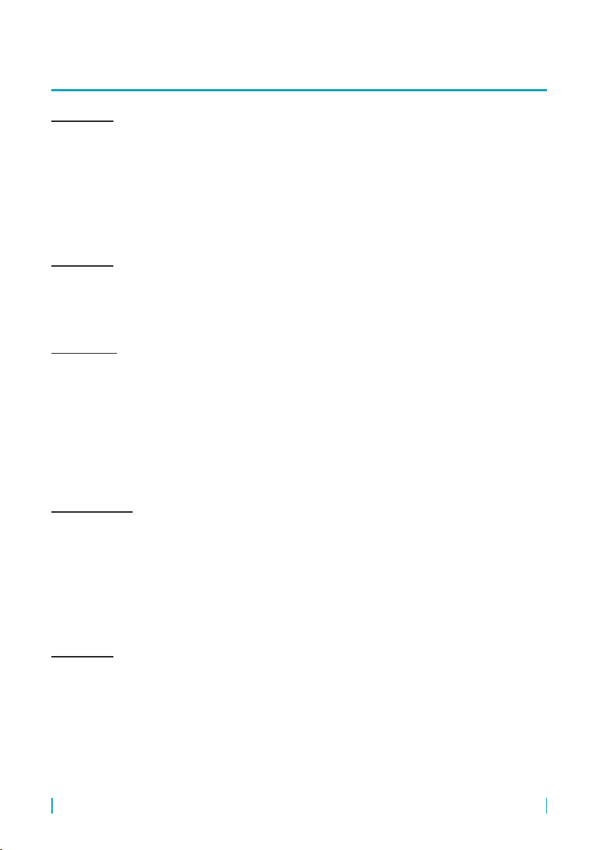
1. At the rope electrode, it is necessary to loosen three fastening screws on the weight
and to pull out the end of the rope, see g. 19.
2. Make sure that the rope length is correct after shortening – the rope is suspended
in the weight up to a distance of approximately 50 mm. Ideally, shorten the rope us-
ing diagonal cutting pliers. Be careful to prevent the end of the
cable from fraying.
3. Insert the end of the rope back into the weight and secure it in
place by tightening all three screws.
Fig. 19: Picture of the rope
with the weight
60
50
20
© Dinel, s.r.o. DLS–27
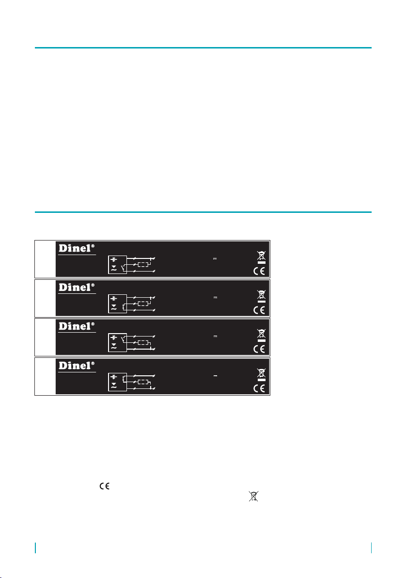
Labels for device of the type DLS–27N:
Dinel, s.r.o. guarantees for the period of three (3) years that the product has the characteristics as
mentioned in the technical specication.
Dinel, s.r.o. is liable for defects ascertained within the warranty period and were claimed in writing.
This guarantee does not cover the damages resulting from misuse, improper installation or incorrect
maintenance.
This guarantee ceases when the user or the other person makes any changes on the product or the
product is mechanically or chemically damaged, or the serial number is not readable.
The warranty certicate must be presented to exercise a claim.
In the case of a rightful complaint, we will replace the product or its defective part. In both cases, the
warranty period is extended by the period of repair..
U
I
U
I
7...36V
3/10mA
200 mA
7...36V
3/10mA
200 mA
BN
BU
BK
+U
0V
BN
BU
BK
+U
0V
Iomax
Iomax
BN
BN
BU
BU
BK
BK
+U
+U
0V
0V
U
I
U
I
7...36V
3/10mA
200 mA
7...36V
3/10mA
200 mA
Iomax
Iomax
DLS-27N_-__-_-NO_-___ E____ No.: ______Cable: __ m
DLS-27N_-__-_-NC_-___ E____ No.: ______Cable: __ m
DLS-27N_-__-_-NO_-___ E____ No.: ______Cable: __ m
DLS-27N_-__-_-PO_-___ E____ No.: ______Cable: __ m No.: ______Cable: __ m
DLS-27N_-__-_-PC_-___ E____ No.: ______Cable: __ m No.: ______Cable: __ m
IP67
IP67
IP67
IP67
Dinel, s.r.o.
U Tescomy 249
760 01 Zlín
Czech Republic
www.dinel.cz
Dinel, s.r.o.
U Tescomy 249
760 01 Zlín
Czech Republic
www.dinel.cz
Dinel, s.r.o.
U Tescomy 249
760 01 Zlín
Czech Republic
www.dinel.cz
Dinel, s.r.o.
U Tescomy 249
760 01 Zlín
Czech Republic
www.dinel.cz
U
I
U
I
7...36V
3/10mA
200 mA
7...36V
3/10mA
200 mA
BN
BU
BK
+U
0V
BN
BU
BK
+U
0V
Iomax
Iomax
BN
BN
BU
BU
BK
BK
+U
+U
0V
0V
U
I
U
I
7...36V
3/10mA
200 mA
7...36V
3/10mA
200 mA
Iomax
Iomax
DLS-27N_-__-_-NO_-___ E____ No.: ______Cable: __ m
DLS-27N_-__-_-NC_-___ E____ No.: ______Cable: __ m
DLS-27N_-__-_-NO_-___ E____ No.: ______Cable: __ m
DLS-27N_-__-_-PO_-___ E____ No.: ______Cable: __ m No.: ______Cable: __ m
DLS-27N_-__-_-PC_-___ E____ No.: ______Cable: __ m No.: ______Cable: __ m
IP67
IP67
IP67
IP67
Dinel, s.r.o.
U Tescomy 249
760 01 Zlín
Czech Republic
www.dinel.cz
Dinel, s.r.o.
U Tescomy 249
760 01 Zlín
Czech Republic
www.dinel.cz
Dinel, s.r.o.
U Tescomy 249
760 01 Zlín
Czech Republic
www.dinel.cz
Dinel, s.r.o.
U Tescomy 249
760 01 Zlín
Czech Republic
www.dinel.cz
Symbol of producer: logo Dinel®
Contact: Dinel,s.r.o., U Tescomy 249, 760 01 Zlín, www.dinel.cz
Type of level meter: DLS–27N_–__–_–___–___ Exxxx
Cable length: Cable: _ _ m
Serial number: Ser. No.: ______ – (from the left: production year, serial production number)
Supply voltage: U = 7...36V=
Current supply: I = 3 / 10 mA
Maximum switching current: Iomax = 200 mA
Compliance mark:
Protection class: IP67, Electro-waste take-back system mark:
This manual suits for next models
8
Table of contents
Other Dinel Accessories manuals


