Dinel RFLS-28 1B Series User manual

Read the instructions published in this manual carefully before using the level meter for the rst time.
Keep the manual in a safe place. The manufacturer reserves the right to implement changes without prior notice.
high-frequency level sensor
RFLS–28
INSTRUCTION MANUAL


1. Basic description.......................................................................................................................5
2. Sensor variants..........................................................................................................................5
3. Dimensional drawing ...............................................................................................................6
4. Installation and putting into operation..................................................................................7
5. Electrical connection.................................................................................................................8
5.1. Type RFLS-28N-_-_-P-_ electrical connection .............................................................8
5.2. Type RFLS-28N-_-_-PD-_ electrical connection...........................................................9
6. Settings elements .................................................................................................................. 11
7. Status indication .................................................................................................................... 12
8. Settings.................................................................................................................................... 13
8.1. Settings using the magnetic pen - RFLS-28_-_-_-P/PD-_ ........................................ 15
8.2. Settings RFLS-28_-_-_-PD-_ using the SSU-1212-AD unit ....................................... 16
8.3. Settings “medium window” mode – media resolution function .......................... 20
9. Mechanical mounting ........................................................................................................... 22
10. Sensor variant with the “PD” output with diagnostics ...................................................... 26
11. Order code.............................................................................................................................. 27
12. Accessories ............................................................................................................................. 28
13. Resilience of O-rings.............................................................................................................. 29
14. Safety, protection, and compatibility .................................................................................. 30
15. Functional safety.................................................................................................................... 30
16. Use, operation, and maintenance ....................................................................................... 30
17. Putting out of operation or disposal ................................................................................... 31
18. General conditions and warranty ........................................................................................ 31
19. Product marking .................................................................................................................... 32
20. Technical parameters............................................................................................................ 33
21. Packing, shipping, and storage............................................................................................. 35
RFLS–28 © Dinel, s.r.o.
4
To ensure the maximum safety of control processes, we have dened the following safety instruc-
tions and information. Each instruction is labelled with the appropriate pictogram.
This symbol informs you about particularly important instructions for installation and opera-
tion of the equipment or dangerous situations that may occur during installation and opera-
tion. Not observing these instructions may cause disturbance, damage, or destruction of the
equipment or may cause injury.
This symbol indicates particularly important device characteristics.
This symbol indicates helpful additional information.
All operations described in this instruction manual must only be carried out by trained
personnelorbyanaccreditedperson.Warrantyandpostwarrantyservicemustbeexclusively
carried out by the manufacturer.
Improper use, installation, or adjustment of the sensor can lead to application failures
(overlling tanks or damage to system components).
The manufacturer is not responsible for improper use, loss of work caused by either direct
or indirect damage, or for expenses incurred at the time of installation or during the period
of use of the level sensors.

5
© Dinel, s.r.o. RFLS–28
The RFLS–28 high-frequency level sensor is designed for industrial use for limit sensing of liquid
and paste media. The high-frequency level sensor may be a direct replacement for a vibrating level
sensor, or for a capacitive level sensor in the case of more demanding applications. The media may
be electrically conductive or non-conductive with any permittivity. The sensor can be installed in
metal or plastic tanks, lling tanks, sumps, etc.
The RG variant can be installed using the TN-28 extension tube or in a similar way.
The sensor works on the high frequency band, enabling reliable detection of the level of media, and
eliminating deposits or foam on the electrode. The sensor suppresses the inuence of deposits of
viscous media (ketchup, yoghurt, mayonnaise, pâtés, syrups, jams, creams, soap) as well as elec-
trically conductive adhesive products (detergents, lyes, chemicals).
The sensor can be set up by applying a magnetic pen to sensitive spots (variants RFLS-28_-_-_-P/
PD-_) or using the programming wire (variant RFLS-28_-_-_-PD-_). For remote parametrization
using the programmable wire, the special SSU-1212-AD unit is used.
The sensors can be set to perform:
• simple sensing of the presence of the medium (medium/air)
• distinction of the interface between two media (medium/medium), e.g. water/oil
• selective distinction of a specic medium (medium window function), the function can distin-
guish e.g. oil from water and air, or detect only beer foam and ignore beer and air, etc.
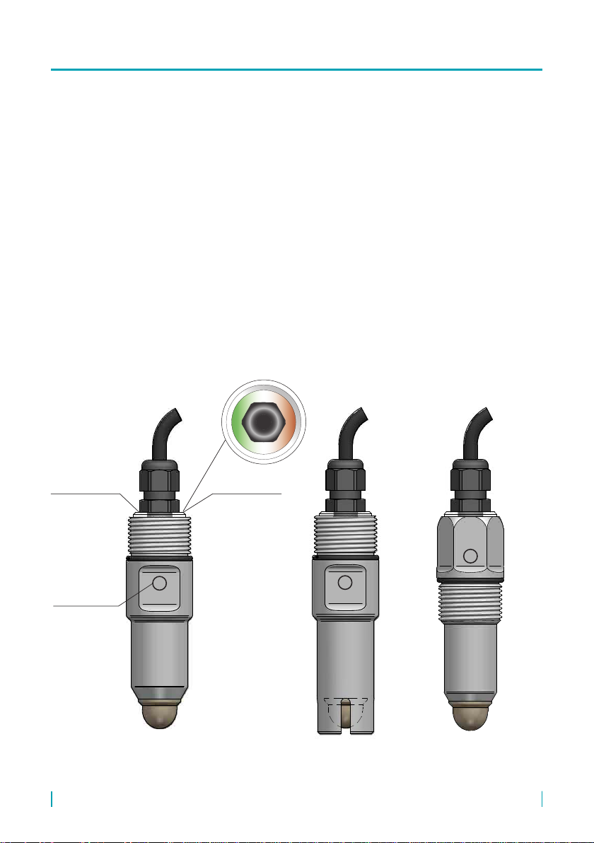
The sensor is made from a stainless steel housing at one end terminated by a sensing electrode,
and terminated at the other end and by an enclosure with a status indicator, control elements, and
electrical connection. The setting elements are on the sides of the sensor. The sensors are manu-
factured for use in non-explosive areas only.
VARIANTS
name minimum
temperature type
RFLS–28_–1B from -40°C NBR O-ring, for sensing various liquids, mashed and paste
materials, also appropriate for oil
RFLS–28_–10B from -40°C with protective crown, NBR O-ring, for sensing various liquids,
mashed and paste materials, also appropriate for oil
RFLS–28_–1E from -40°C EPDM O-ring, for sensing various liquids, mashed and paste
materials, also appropriate for acids or bases
RFLS–28_–10E from -40°C With protective crown, EPDM O-ring, for sensing various liquids,
mashed and paste materials, also appropriate for acids or bases
RFLS–28_–1V from -20°C FPM (Viton) O-ring, for sensing various liquids, mashed and paste
materials, also appropriate for oil, acids, bases, or asphalt and tar
RFLS–28_–10V from -20°C
with protective crown, FPM (Viton) O-ring, for sensing various
liquids, mashed and paste materials, also appropriate for oil,
acids, bases, or asphalt and tar
RFLS–28 © Dinel, s.r.o.
6
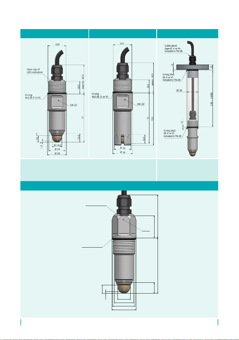
RFLS–28_–1_–RG–_–_ RFLS–28_–10_–RG–_–_ Extension tube TN-28-P***
OK 22
O-ring
4x2 (B, E ro V)
G¾"
42,5approx.
18,5
12,5
14,6
Ø
24
Ø
28
Ø
10~ **
2~ *
71
clear cap of
LED indication
G¾"
71 18,5
42,5approx.
73,5
OK 22
O-ring
4x2 (B, E or V)
24
28
12,5
Ø
Ø
L50 ... L3000
28
~ 2
12
O-ring 24x2
(B, E or V)
included in TN-28
O-ring 24x2
(B, E or V)
included in TN-28
Cable gland
(type B, V or H)
included in TN-28
~ 2
Ø
The switching point is the same for both sensor variants.
* Typical switching point position for water (factory default).
** Typical switching point position for oil.
*** Extension tube variants:
P - ange (in gure),
Z - thread G1“, Cl - Tri-Clamp
see the accessories data sheet for
the TN-28 extension tube
RFLS-28_-1_-FG–_–_
O-ring 24x2
(B, E or V)
2~ *
10~ **
G ¾"
OK 24
clear cap of
LED indication
28
Ø
22
Ø
14,6
Ø
12,5 64 49,5
approx.
25,5

7
© Dinel, s.r.o. RFLS–28
Variant “B” with a stand-
ard cable gland
20
53
43
ø 17
20
53
43
ø 17
20
53
43
ø 17
20
53
43
ø 17
20
53
43
ø 17
20
53
43
ø 17
Variant “V” with plastic cable
gland with spiral relief – in the
case of increased mechanical wear
on the cable.
Spiral relief
clear cap
LED indication
clear cap
LED indication
Spiral relief
Variant “H” with cable
gland for protective hoses
– for use in an outdoor area
or in an area with high hu-
midity.
protective hose
(ø 13 mm)
protective hose
(ø 13 mm)
Please follow the next 3 steps:
• For , see chapter 9
• For , see chapter
• For , see chapter
RFLS–28 © Dinel, s.r.o.
8
The electrical connection can only be made when de-energised!
The power supply must be designed as a stabilised source of low safe voltage with galvanic
isolation. If a switched power supply is used, its design must effectively suppress common
mode interference. If the switched power supply is equipped with a PE protective terminal,
it must be strictly earthed!
If the level meter (sensor) is to be installed in an outdoor environment more than 20 m from
an outdoor switchboard or an enclosed building, the electrical supply to the level meter
(sensor) must be supplemented with suitable overvoltage protection.
In the case of strong environmental electromagnetic interference, common routing of the
signal cable with the power cable or if the length is more than 30 m, we recommend using
a shielded cable and grounding the shielding on the power source side.
RFLS-28_-_-P sensors are permanently connected to evaluation units by a PVC cable.
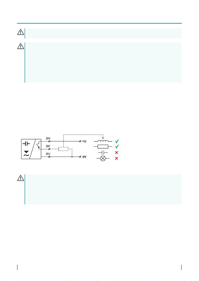
Sensors with PNP output can only be loaded with a resistive or inductive load. The capacitative
loads and low resistance loads (bulb) are evaluated by the sensor as a short circuit.
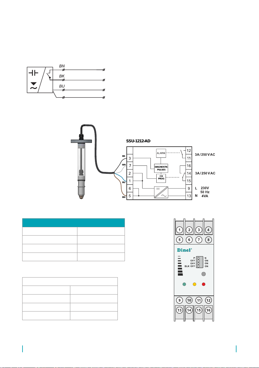
Connection diagrams are listed in the gure below.
5.1. Type RFLS-28N-_-_-P-_ electrical connection
Legend:
BK – black
BN – brown
BU – blue
Fig. 1: Connection of the RFLS-28_-_-P-_ sensor with PNP output
9
© Dinel, s.r.o. RFLS–28
The SSU-1212-D power supply and switching unit is intended for the evaluation of the state of the
connected sensor and its transformation to a power contact. In addition, the unit is able to evaluate
diagnostic messages generated by the connected sensor. The programming wire P is not con-
nected to the unit and its end must be properly insulated.
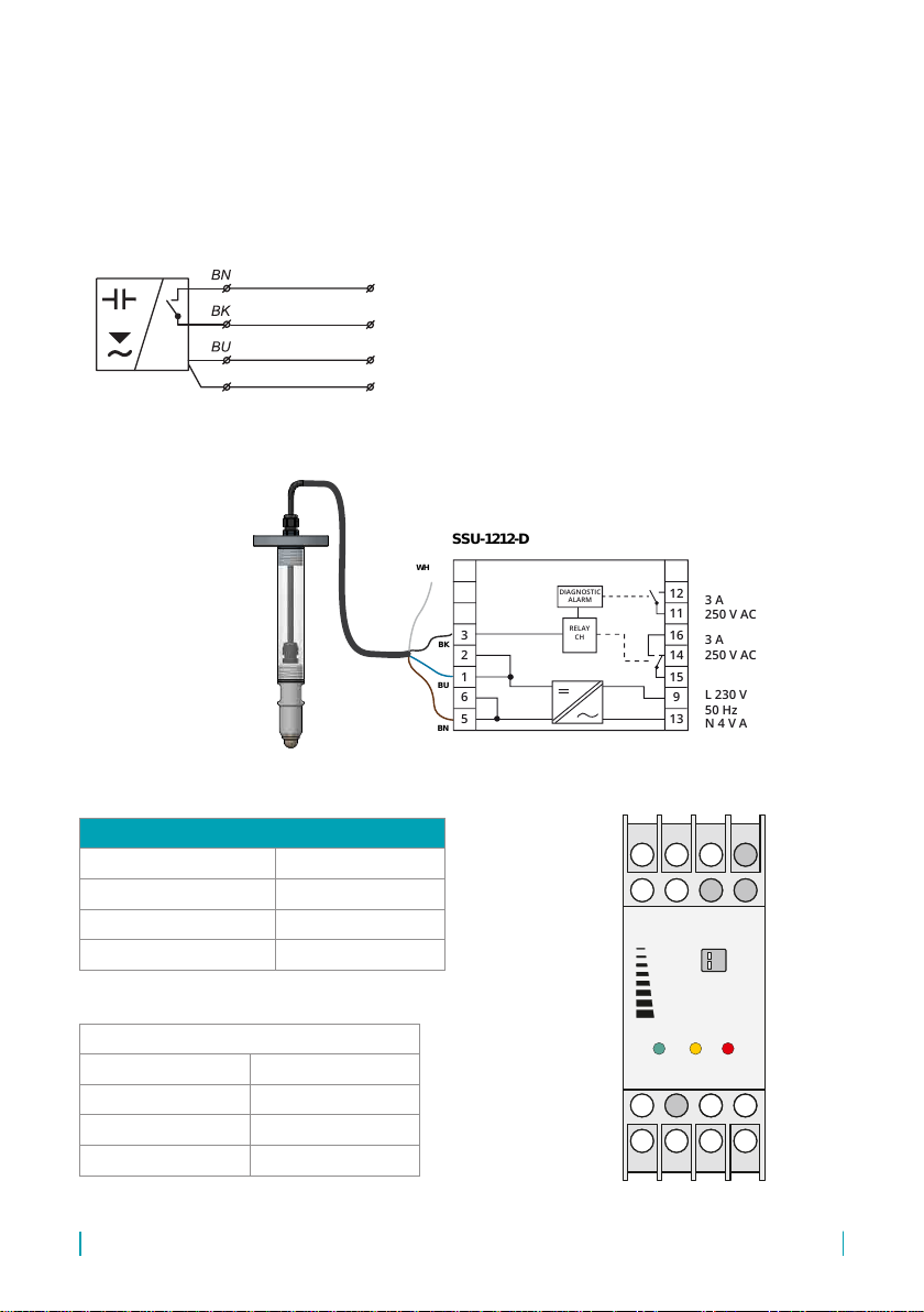
5.2. Type RFLS-28N-_-_-PD-_ electrical connection
5.2.1. Connection to the SSU-1212-D unit – diagnostic function only
Legend:
BK – black
BN – brown
BU – blue
WH – white
P
OUT
+U
0V
WH
Fig. 2: Connection of the RFLS-28_-_-PD-_ sensor with PNP output and diagnostic function
Fig. 3: Connection of the sensor to the SSU-1212-D unit
BK
SSU-1212-D
WH
BU
BN 5
6
1
2
3
N 4 V A
L 230 V
50 Hz
3 A
250 V AC
3 A
250 V AC
13
9
15
14
16
11
12
RELAY
CH
DIAGNOSTIC
ALARM
2
6
1
5
3
7
4
8
10
14
9
13
11
15
12
16
Dinel
BLK OFF ON
ALARM
POWER
PN
OUT
SSU-1212-D
RFLS-28_-_-_-PD-_
BK
SSU-1212-D
WH
BU
BN 5
6
1
2
3
N 4 V A
L 230 V
50 Hz
3 A
250 V AC
3 A
250 V AC
13
9
15
14
16
11
12
RELAY
CH
DIAGNOSTIC
ALARM
2
6
1
5
3
7
4
8
10
14
9
13
11
15
12
16
Dinel
BLK OFF ON
ALARM
POWER
PN
OUT
SSU-1212-D
Legend
BK black
WH white
BU blue
BN brown
PNP output type sensor connection
+U sensors terminal No. 5 or 6
Q output of the sensor terminal No. 3
0 V of the sensor terminal No. 1 or 2
programming wire P not connected
RFLS–28 © Dinel, s.r.o.
10
The SSU-1212-AD power supply and switching unit is intended for the evaluation of the state of the
connected sensor and its transformation to a power contact. In addition, the unit is able to evaluate
diagnostic messages generated by the connected sensor and set it remotely.
5.2.2. Connection to the SSU-1212-AD unit – diagnostic function + remote settings
Legend:
BK – black
BN – brown
BU – blue
WH – white
P
OUT
+U
0V
WH
Fig. 2: Connection of the RFLS-28_-_-PD-_ sensor with PNP output and diagnostic function
Fig. 3: Connection of the sensor to the SSU-1212-AD unit
SET CH
SET
SETTING
POWER
SSU-1212-AD
OUT ALARM
7DIAGNOSTIC
PULSES
CH
PROG
BK
SSU-1212-AD
WH
BU
BN
RFLS-28_-_-_-PD-_
SET CH
SET
SETTING
POWER
SSU-1212-AD
OUT ALARM
7DIAGNOSTIC
PULSES
CH
PROG
BK
SSU-1212-AD
WH
BU
BN
Legend
BK black
WH white
BU blue
BN brown
PNP output type sensor connection
+U sensors terminal No. 5 or 6
Q output of the sensor terminal No. 3
0 V of the sensor terminal No. 1 or 2
programming wire P terminal No. 7
11
© Dinel, s.r.o. RFLS–28
The settings elements are used to set the sensitivity and behaviour of the sensor. The RFLS-28
sensor can always be set using a magnetic pen by touching the ON or OFF magnetically sensitive
spots on the sensor. The RFLS-28N-_-_- PD-_ variant is also tted with a setting wire for remote
parametrisation of the sensor. Remote parametrisation enables all the same sensor options to be
set as when setting with the magnetic pen.
With the RFLS-28N-RG-_- P -_ variant with no option of remote parametrisation, settings needs to
be performed before the sensor is installed in the tank, because setting is unavailable after instal-
lation in the tank.
• Quick settings – the user does not know precisely what medium the sensor should be set to,
but just wants to start up the sensor (usually upon receiving it) and check to see if the sensor
is generally functional.
• Basic settings – the user has the medium available and can perform ooding and drainage
on the sensor.
• Medium window settings – the user has the medium available and can perform ooding and
drainage on the sensor.
Orange LEDGreen LED
Sensitive spot
for the magnetic
pen
Fig. 4: Positions of the settings and indication elements on the sensor
M
ON
M
ON
M
ON

RFLS–28 © Dinel, s.r.o.
12
Function indication on the sensor indication on the unit
standard operation
sensor open
standard operation
sensor closed
incorrect setting
setting up
magnetic pen
application the status is unchanged
settings
PD version only
sensor malfunction
status open
sensor malfunction
status closed
0,4
0,4
0,2
0,2
0,1
0,1
0,4
0,4
0,4
0,2
0,2
1
1
0,10,1 0,10,1 0,1
0,1
0,1
0,4
0,4
0,4
0,2
0,4
0,4
0,2
0,2
sec.
sec.
sec.
sec.
sec.
sec. sec.
sec.
sec.
13
© Dinel, s.r.o. RFLS–28
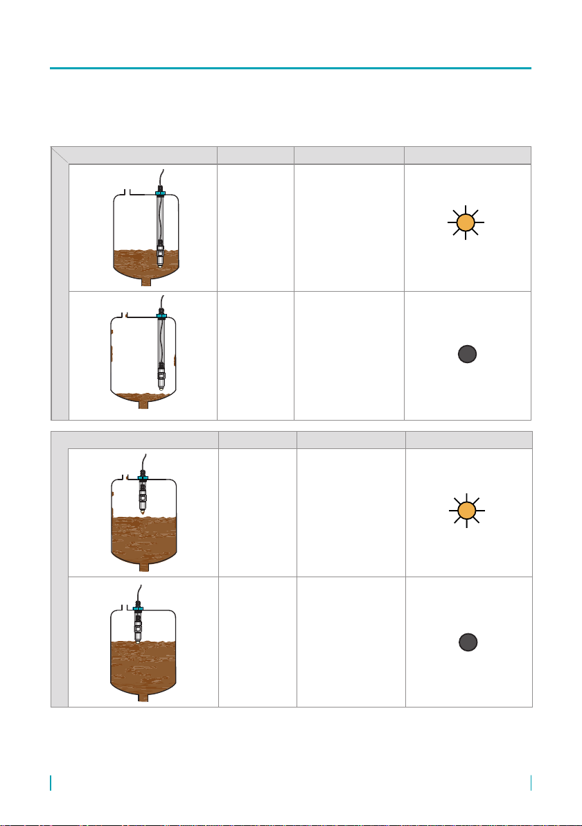
For safety reasons, for scanning min. level, we recommend setting “O-mode” (sensor closes when submerged).
A faulty sensor or wiring will take eect here in the same way as level emergency conditions by opening the sensor.
Analogously, for the max. level, we recommend setting “C-mode” (sensor opens when submerged).
level state mode output state Orange LED
maximum level sensing
CCLOSED
(illuminated)
COPEN
(not illuminated)
level state mode output state Orange LED
minimum level sensing
OCLOSED
(illuminated)
OOPEN
(not illuminated)
The sensor can be set to normally closed “O-mode” or to normally open “C-mode” switch types.

RFLS–28 © Dinel, s.r.o.
14
For safety reasons, for scanning min. level, we recommend setting “O-mode” (sensor closes when submerged).A
faulty sensor or wiring will take eect here in the same way as level emergency conditions by opening the sensor.
Analogously, for the max. level, we recommend setting “C-mode” (sensor opens when submerged).
level state mode output state Orange LED
maximum level sensing
CCLOSED
(illuminated)
COPEN
(not illuminated)
level state mode output state Orange LED
minimum level sensing
OCLOSED
(illuminated)
OOPEN
(not illuminated)
The sensor can be set to normally closed “O-mode” or to normally open “C-mode” switch types.

15
© Dinel, s.r.o. RFLS–28
Unless otherwise agreed, “O-mode” is set on all sensors straight from the factory.
When using the “quick settings” function, the sensor does not eliminate the presence of
deposits and foam on the electrode. The manufacturer recommends performing the basic
settings as soon as possible.
This mode is only suitable for verifying the sensor before commissioning if the measured medium
is not available.
1. The sensor is turned with the measuring electrode into the free space.
2. Apply the magnetic pen for at least 5 to 10 seconds to the ON sensitive spot on the sensor
(at rst, both LEDs light up. After approx. 3 seconds, the orange LED ashes 3 times, and after
another approx. 2 seconds the orange LED ashes again 3 times. You can now remove the
magnetic pen).
The sensor is now set to O-mode (closes when submerged).
1. The sensor is turned with the measuring electrode into the free space.
2. Apply the magnetic pen for at least 5 to 10 seconds to the OFF sensitive spot on the
sensor (at rst, both LEDs light up. After approx. 3 seconds, the orange LED ashes 3 times,
and after another approx. 2 seconds the orange LED ashes again 3 times. You can now
remove the magnetic pen).
The sensor is now set to C-mode (opens when submerged).
Settings needs to be performed prior to installing the sensor in the TN-28 extension tube.
With the RFLS-28N-RG-_- P -_ variant with no option of remote parametrisation, settings needs to
be performed before the sensor is installed in the tank, because setting is unavailable after instal-
lation in the tank.
While setting up the RFLS-28 sensor, it is important to monitor both LEDs. Therefore, settings must
be performed before installing the sensor in the extension tube.
• Install the electrical connection – see Chapter 5
• In the case of simple sensing of non-adhering media, you can use the Quick settings speci-
ed in chap. 8.1.1. Otherwise, it is necessary to perform the Basic settings - with the
medium present.
• Prepare the measured medium in an auxiliary vessel.
• If you want to sense the presence of the medium (medium/air) or detect the interface of two
dierent media (medium/medium), such as water/oil, follow the instructions provided in chap.
8.1.2. Basic settings.
• If you want to selectively detect a specic medium, follow the instructions provided in chap.
8.1.3. setting up “medium window” mode.

RFLS–28 © Dinel, s.r.o.
16
For safety reasons, we recommend setting “O-mode” for level sensing (the sensor closes when
submerged). A faulty sensor or wiring will take effect here in the same way as level emergency
conditions by opening the sensor. Analogously, for the maximum level, it is recommended to set
“C-mode” (the sensor opens when submerged).
For setting the sensitivity and switching mode, where it is possible to submerge the sensor in or
remove it from the medium. When using this setting, the sensor eliminates the presence of deposits
and foam on the electrode.
1. Immerse the sensor electrode in the medium to be measured (in the case of the detection of a
two-media interface, place the electrode in the lower medium).
2. Apply the magnetic pen for 2 to 4 seconds to the ON sensitive spot of the sensor (until both
LEDs are illuminated) and then remove the magnetic pen. The settings are conrmed by three
ashes of the orange LED.
3. Take the sensor out of the medium (in the case of the detection of a two-media interface, place
the electrode in the upper medium). Leave any deposits on the electrode.
4. Apply the magnetic pen for 2 to 4 seconds to the OFF sensitive spot of the sensor (until
both LEDs are illuminated) and then remove the magnetic pen. The settings are conrmed by
three ashes of the orange LED.
5. Check the status of the indicators:
• If the orange LED is not illuminated and the green LED is ashing, the sensor is correctly set.
• If the orange and green LEDs are ashing alternately, the sensor did not recognise the limits
for closing and opening. In this case, nd out whether the minimum and maximum levels
have been set too close to one another.
1. Immerse the sensor electrode in the medium to be measured (in the case of the detection of a
two-media interface, place the electrode in the lower medium).
2. Apply the magnetic pen for 2 to 4 seconds to the OFF sensitive spot of the sensor (until
both LEDs are illuminated) and then remove the magnetic pen. The settings are conrmed by
three ashes of the orange LED.
3. Pull the sensor out of the medium. (when detecting a two-media interface, place the electrode
in the upper medium). Leave any deposits on the electrode.
4. Apply the magnetic pen for 2 to 4 seconds to the ON sensitive spot of the sensor (until both
LEDs are illuminated) and then remove the magnetic pen. The settings are conrmed by three
ashes of the orange LED.
5. Check the status of the indicators:
• If the orange LED is illuminated and the green LED is ashing, the sensor is correctly set.
• If the orange and green LEDs are ashing alternately, the sensor did not recognise the limits
for closing and opening. In this case, nd out whether the minimum and maximum levels
have been set too close to one another and repeat the set-up if necessary.

17
© Dinel, s.r.o. RFLS–28
The sensor can also be used to distinguish a specic medium from others – using the "medium
window" function. E.g. the sensor can distinguish oil from water and air, detect only beer foam and
ignore beer and air, etc. To set the sensitivity and switching mode for the required medium. With
this setting, the sensor does not react to being submerged in a medium with a dierent permittivity.
Orange LED
not illuminated
Orange LED
not illuminated Orange LED
lit
1. Immerse the sensor electrode in the medium to be measured.
2. Apply the magnetic pen for at least 10 seconds to the ON sensitive spot of the sensor (at
rst both LEDs are illuminated. After approx. 3 seconds, the orange LED ashes 3 times. After
another approx. 2 seconds the orange LED ashes again 3 times, and after approx. 5 seconds
the orange LED ashes 3 times again. You can now remove the magnetic pen).
The sensor is now set to O-mode (closes when submerged in the required medium).
3. Check the status of the indicators:
• If the orange LED is illuminated and the green LED is ashing, the sensor is correctly set.
Fig. 5: “Medium window” mode – only detection of the required medium:
(e.g.: only beer foam, beer and air are ignored)
Orange LED
not illuminated
Orange LED
lit
Orange LED
not illuminated

RFLS–28 © Dinel, s.r.o.
18
1. Immerse the sensor electrode in the medium to be measured.
2. Apply the magnetic pen for at least 10 seconds to the OFF sensitive spot of the sensor (at
rst both LEDs are illuminated. After approx. 3 seconds, the orange LED ashes 3 times. After
another approx. 2 seconds the orange LED ashes again 3 times, and after approx. 5 seconds
the orange LED ashes 3 times again. You can now remove the magnetic pen).
The sensor is now set to C-mode (opens when submerged in the required medium).
3. Check the status of the indicators:
• If the orange LED is not illuminated and the green LED is ashing, the sensor is correctly set.
With the variant provided with the remote parametrisation option (RFLS-28_-_-_-PD-_), it is pos-
sible to set the sensor using the programming wire and/or the special SSU-1212-AD evaluation
unit. This unit is equipped with a contact (terminal No. 7) to connect the programming wire allowing
all setting options of the sensor to be performed. This concerns the quick settings as per para-
graph 8.1.1., the basic settings as per paragraph 9.4, and setting “medium window” mode as per
paragraph 8.1.3.
The unit has one input for the connection of the operating sensor (marked as IN, terminal No. 3).
The operating sensor enables the control of the operating relay (terminals 14, 15, 16). The unit is
tted with a diagnostic function monitoring the correct operation of the connected sensor, and the
remote parametrisation function for the connected sensor using the W programming wire. The pro-
gramming wire is connected to the terminal marked P (terminal No. 7).
This mode is only suitable for verifying the sensor before commissioning if the measured medium
is not available.
1. The sensor is turned with the measuring electrode into the free space.
2. Switch the SET CH switch to the ON position and the SET switch to the OFF position
3. Press the SETTING button for 5–10 seconds. The setting is conrmed in the following manner.
After approximately 3 seconds, the orange LED ashes three times. After another approximate-
ly 2 seconds, the orange LED ashes three times again. Now, release the SETTING button. The
sensor is now set to O-mode (closes when submerged).
4. Check the status of the ALARM indicator. If the red LED is not ashing, the sensor is set cor-
rectly. If it is ashing, the sensor is set incorrectly. Repeat the setting.
5. Switch the SET CH switch to the OFF position.
Setting using the programming wire can be performed even after the installation of the RFLS-
28 sensor with the TN-28 extension tube in the tank.
1212

19
© Dinel, s.r.o. RFLS–28
A function suitable for setting the sensor to simple sensing or resolution of the interface of two me-
dia. For setting the sensitivity and switching mode, where it is possible to submerge the sensor in or
remove it from the medium. When using this setting, the sensor eliminates the presence of deposits
and foam on the electrode.
1. Immerse the sensor electrode in the medium to be measured (in the case of the detection of a
two-media interface, place the electrode in the lower medium).
2. Switch the SET CH and SET switches to the ON position.
3. Press the SETTING button for approx. 2 seconds. The setting is conrmed by three ashes of
the orange LED.
4. Take the sensor out of the medium (in the case of the detection of a two-media interface, place
the electrode in the upper medium). Leave any deposits on the electrode.
5. Switch the SET switch to the OFF position.
6. Press the SETTING button for approx. 2 seconds. The setting is conrmed by three ashes of
the orange LED.
7. Check the status of the ALARM indicator. If the red LED is not ashing, the sensor is set cor-
rectly. If it is ashing, the sensor is set incorrectly. Repeat the setting.
8. Switch the SET CH switch to the OFF position.
1. The sensor is turned with the measuring electrode into the free space.
2. Switch the SET CH and SET switches to the ON position
3. Press the SETTING button for 5–10 seconds. The setting is conrmed in the following manner.
After approximately 3 seconds, the orange LED ashes three times. After another approxi-
mately 2 seconds, the orange LED ashes three times again. Now it is possible to release the
SETTING button. The sensor is now set to C-mode (closes when submerged in the required
medium).
4. Check the status of the ALARM indicator. If the red LED is not ashing, the sensor is set cor-
rectly. If it is ashing, the sensor is set incorrectly. Repeat the setting.
5. Switch the SET CH switch to the OFF position.

RFLS–28 © Dinel, s.r.o.
20
1. Immerse the sensor electrode in the medium to be measured (in the case of the detection of a
two-media interface, place the electrode in the lower medium).
2. Switch the SET CH switch to the ON position and the SET switch to the OFF position.
3. Press the SETTING button for approx. 2 seconds. The setting is conrmed by three ashes of
the orange LED.
4. Take the sensor out of the medium (in the case of the detection of a two-media interface, place
the electrode in the upper medium). Leave any deposits on the electrode.
5. Switch the SET switch to the ON position.
6. Press the SETTING button for approx. 2 seconds. The setting is conrmed by three ashes of
the orange LED.
7. Check the status of the ALARM indicator. If the red LED is not ashing, the sensor is set cor-
rectly. If it is ashing, the sensor is set incorrectly. Repeat the setting.
8. Switch the SET CH switch to the OFF position.
The sensor can be used to distinguish a specic medium from others. E.g. the sensor can distin-
guish oil from water and air, detect only beer foam and ignore beer and air, etc. With this mode, the
sensor does not react to being submerged in a medium with a dierent permittivity.
Orange LED
not illuminated
Orange LED
not illuminated Orange LED
lit
Fig. 6: “Medium window” mode – only detection of the required medium:
(e.g.: only beer foam, beer and air are ignored)
Orange LED
not illuminated
Orange LED
lit
Orange LED
not illuminated
This manual suits for next models
6
Table of contents
Other Dinel Accessories manuals


Popular Accessories manuals by other brands

Swisher
Swisher PowerBlade PBP-3640 Assembly instructions

Airspan
Airspan Air4Gp installation guide

Whale
Whale INSTANT MATCH SDP134T Installation guidelines

Honeywell
Honeywell T7147 Product data

Interlogix
Interlogix International Shock Sensor installation instructions

Vega
Vega VEGAPULS 63 operating instructions

Clockaudio
Clockaudio CDT100 user manual

BERKSHIRE PRODUCTS
BERKSHIRE PRODUCTS 2010 user manual

Siko
Siko LE100/1 Translation of the original installation instructions

Siko
Siko MSA213K installation instructions

Digital Dowsing
Digital Dowsing Xcam SLS quick start guide

Pepperl+Fuchs
Pepperl+Fuchs U-P R4 Series manual


