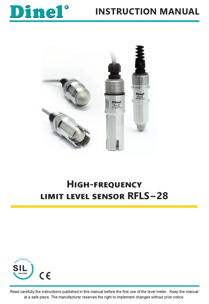
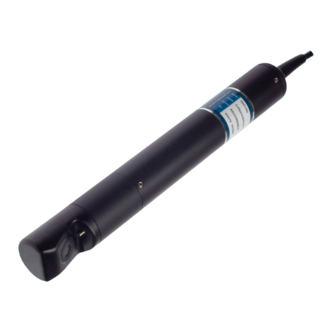
Dinel RFLS-35 User manual

Read carefully the instructions published in this manual before the rst use of the level meter. Keep the manual
at a safe place. The manufacturer reserves the right to implement changes without prior notice.
High-frequency limit level sensor
RFLS – 35
INSTRUCTION MANUAL
průmyslová elektronika

1. Basic description.......................................................................................................................4
2. Variants of sensors ...................................................................................................................5
3. Dimensional drawing ................................................................................................................5
4. Installation and putting into operation .......................................................................................7
5. Installation instructions .............................................................................................................8
6. Electrical connection...............................................................................................................10
7. Control elements.....................................................................................................................11
8. Settings...................................................................................................................................12
9. Function and status indication ................................................................................................15
10. Order code..............................................................................................................................16
11. Correctspecicationexamples...............................................................................................16
12. Accessories ............................................................................................................................16
13. Safety,protections,compatibilityandexplosionproof...........................................................17
14. Use, manipulation and maintenance ......................................................................................17
15. General, conditions and warranty ...........................................................................................18
16. Marking of labels.....................................................................................................................18
17. Technicalspecications..........................................................................................................20
18. Packings, shipping and storage..............................................................................................22

RFLS–35 © Dinel, s.r.o.
3
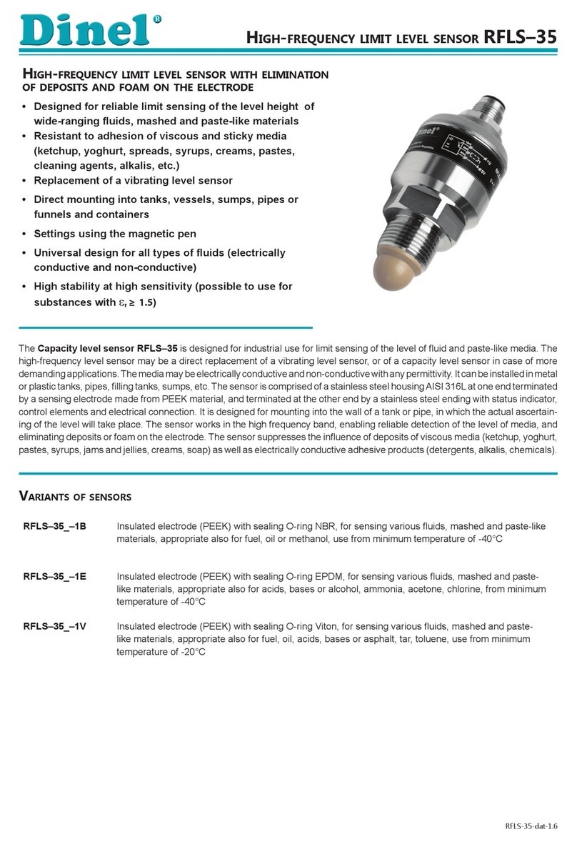
The high-frequency level sensor RFLS–35 is designed for industrial use for limit sensing of the
level of liguid and paste-like media. The high-frequency level sensor may be a direct replacement of
a vibrating level sensor, or of a capacity level sensor in case of more demanding applications. The
media may be electrically conductive or non-conductive with any permittivity. It can be installed in
metalorplastictanks,pipes,llingtanks,sumps,etc.
It is mainly designed for mounting into the wall of a tank or pipe, in which the actual detection of the
level will take place. The sensor works in the high frequency band, enabling reliable detection of
the level of media, and eliminating deposits or foam on the electrode. The sensor suppresses the
inuenceofdepositsofviscousmedia(ketchup,yoghurt,pastes,syrups,jamsandjellies,creams,
soap)aswellaselectricallyconductiveadhesiveproducts(detergents,alkalis,chemicals).
Likewise,itispossibletoutilizeittodierentiateaspecicmediafromothers-the"Mediumwindow"
function.E.g.itcandierentiateoilfromwaterandair,detectonlybeerfoamandignorebeerandair,etc.
The sensor is made from a stainless steel housing at one end terminated by a sensing electrode,
and terminated at the other and by an ending with a status indicator, control elements and electrical
connection.
Toensuremaximumsafetyofcontrolprocesses,wehavedenedthefollowingsafetyinstructions
and information. Each instruction is labelled with the appropriate pictogram.
Alert, warning, danger
This symbol informs you about particularly important instructions for installation and operation of
equipment or dangerous situations that may occur during the installation and operation. Not observing
theseinstructionsmaycausedisturbance,damageordestructionofequipmentormaycauseinjury.
Information
This symbol indicates particularly important characteristics of the device.
Note
This symbol indicates helpful additional information.
All operations described in this instruction manual have to be carried out by trained personnel
or by an accredited person only. Warranty and post warranty service must be exclusively
carried out by the manufacturer.
Improper use, installation or set-up of the sensor can lead to crashes in the application.
The manufacturer is not responsible for improper use, loss of work caused by either direct
or indirect damage, and for expenses incurred at the time of installation or during the period
of use of the level sensors.

4
© Dinel, s.r.o. RFLS–35
• RFLS–35_–1B Insulated electrode (PEEK) with sealing O-ring NBR, for sensing
various liquid, mashed and paste-like materials, appropriate also for fuel,
oil or methanol,
use from minimum temperature of -40 °C
• RFLS–35_–1E Insulated electrode (PEEK) with sealing O-ring EPDM, for sensing
various liquid, mashed and paste-like materials, appropriate also for acids,
bases or alcohol, ammonia, acetone, chlorine,
from minimum temperature of -40 °C
• RFLS–35_–1V Insulated electrode (PEEK) with sealing O-ring Viton, for sensing
various liquid, mashed and paste-like materials, appropriate also for fuel,
oil, acids, bases or asphalt, tar, toluene,
use from minimum temperature of -20 °C
• RFLS–35_–2 Insulated electrode (PTFE) without O-ring, for sensing various liquid,
mashed and paste-like materials, especially suitable for aggressive liquids,
use from minimum temperature of -40 °C.
Therearenextperformancesavailable:N– For normal atmospheres, Xi –Explosionproof–intrinsi-
callysafeforhazardous(explosive)areas.andXiM–Explosionproof–intrinsicallysafeforusein
mineswithmethaneorammabledustpresencedanger(seetechnicalspecications).
Measuring
electrode
Sensor
housing
End of sensor
Cable
gland
RFLS–35_–1–G1/2 RFLS–35_–1–G3/4
*Typeofthreads:G3/4;M27x2

RFLS–35 © Dinel, s.r.o.
5
RFLS–35_–2–Cl50
(Tri-clamp)
RFLS–35_–2–G1/2
RFLS–35_–2–Cl34
(Tri-clamp)
*Typeofthreads:G3/4;M27x2
RFLS–35_–2–G3/4

6
© Dinel, s.r.o. RFLS–35
Variant “A” with short
stainless steel gland
Variant “C”
with connector M12
Variant “V” with plastic cable gland with
spiral relief – in case of increased mechani-
cal wear on the cable.
spiral relief
Variant “H” with cable gland for protect-
ed hoses – for using in an outdoor area or in
area with increased moisture.
protective hose
(ø 13 mm)
Variant “B” with plastic
threaded cable gland
Variant “D” with
dustproof cable outlet
Pleasefollownext3steps:
•
•
•

RFLS–35 © Dinel, s.r.o.
7
RFLS level sensors can be mounted in horizontal or inclined position into the shell of a con-
tainer, storage tank or pipe by screwing into the welding ange, or by axing using a nut.
Basic application recommendations are mentioned below.
During assembly into the metal tank or the storage tank, it is not necessary to separately ground
the base of the level sensor
Inthecaseoftheuse for an aggressive medium isnecessary to provethe chemical compatibility
of used materials of the sensor (Tab. Used materials on page 19). This guarantee ceases when
the product is chemically damaged.
Thanks to its design, the sensor is appropriate for detection of the level of viscous and simultane-
ously electrically conductive media (yoghurt,jamsandjellies,mayonnaise,spreads,liquidsoap,
creams or pastes). After setting the sensitivity of the given media, it reliably reacts to the presence
or absence of a medium level. On the contrary, the sensor does not react to remnants and coatings
of viscous media on the measuring electrode.
Fig. 1: Side installation of sensors into a tank with viscous medium
It is recommended to install
sensors in a horizontal pipe
inclined from the side.
or adhering remnants
of liquid at the bottom
of the pipe.
Upon vertical installation of the
sensor in a pipe, pay attention to
potential formation of air pockets,
!!
Fig. 2: Installation of the sensor in a pipe

8
© Dinel, s.r.o. RFLS–35
In the case of side wall mounting.itisnecessarytoavoidlongttingtubes,wheresensedmedium
could remain. We recommend mounting the sensor so that the whole measuring electrode is inside
the tank.
Fig. 3a: Correct and incorrect installation
with a long tube
Installation of the sensor for reliable checking of the level of a liquid with foam on the surface. Sensi-
tivity of the sensor can be set to detect the liquid interface with foam. After a drop in the liquid level,
the sensor does not react to coatings of foam on the electrode.
The LED indicator
“STATE” is dark
The LED indicator
“STATE” shines
Fig. 4: Monitoring the level of foam media
Small Tri-clamp (ø 34 mm), only for liquids with low viscosity.
Fig. 3b: Correct and incorrect installation with
a long tube for process connection with Tri-Clamp
The sensor can be mounted in a tank or at medium inlets. After setting to the level of the given
mediathesensordoesnotreacttothecurrentofowingmedium.
Fig. 5: Option of mounting the sensor in the medium inlet

RFLS–35 © Dinel, s.r.o.
9
A sensor with PNP output can be loaded only by resistive or inductive load. The positive pole of
thesupplyvoltage(+U)isconnectedtothebrownwireBN or pin connector no.1, the negative pole
(0V)isconnectedtothebluewireBU or pin connector no. 3 and load on the black wire BK or pin
connector no. 4.Thecapacitativeloadsandlowresistanceloads(bulb)areevaluatedbythesensor
as a short circuit.
Connection diagrams are listed in Figures 6, 7.
Connection using connector socket shows in Figure 9.
Sensors RFLS-35 with type of cable outlet A, B, V, D or H are connected to assessing units perma-
nently connected by PVC cable. Design diagrams are provided in images 6, 7.
Sensors RFLS-35 with connection method type C are connected to control units by means of a con-
nectorsocketwithcompressioncable(length2or5m),orbymeansofdismountableconnector
socketwithoutcable(seeaccessories),connectorsocketisnotpartofthesensor.Inthiscasethe
cable is connected to the inside pins of the socket according to Figure 9. The recommended diam-
eterofthiscableis4to6mm(therecommendedcross-sectionalareais0.5to0.75mm2).
The connection of the sensor to the connecting device is performed using a suitable three wire
(variantN)ortwowire(variantXiandXiM)cable.ThelengthofthecablefortheXiandXiMvaria-
tionsmustbeselectedwithrespecttothemaximumpermittedparameters(usuallyinductanceand
capacity)oftheoutsideintrinsicallysafecircuitofsupplyunits(NSSU,NDSU,NLCU).
Intheeventthatdismountableconnectorsocketsareused,theouterdiameterofthecableismax.
6 mm.
Fig. 6: PNP output type sensor connection Fig.7: NAMUR type sensors connection
(variants Xi and XiM)
1
3
4
Legend:
(1,...) – numbers of terminals inside the connector socket
BK – Black
BN – Brown
BU – Blue
output (BK)
0V (BU)
+U (BN)
Fig. 9: Inside of the connector socket
(type ELWIKA or ELKA)
0 V (3)
+U (1)
Fig. 8: Connection of the connector
socket on sensor
Uout (4)

10
© Dinel, s.r.o. RFLS–35
Electrical connection can only be made when de-energized!
The source of the power voltage must comprise of a stabilised safe low power source with
galvanic separation. In the event that a switch-mode power supply is used, it is essential that
its construction effectively suppresses common mode interference on the secondary side. In
the event that the switch-mode power supply is equipped with a PE safety terminal, it must
be unconditionally grounded! Spark-safe devices type (RFLS–35Xi and RFLS-35XiM) must
be powered from a spark-safe power source meeting the above-mentioned requirements.
In the event that the level meater (sensor) is installed in an outdoor environment at a distance
greater than 20 m from the outdoor switchboard, or from an enclosed building, it is necessary
to supplement the electrical cable leading to the level meater (sensor) with suitable overvoltage
protection.
With regard to possible occurrence of electrostatic charge on non-conductive parts of the
sensor for explosive areas (RFLS–35Xi and RFLS–35XiM, sensors must be grounded. It will be
done using conductive tank, conductive lid of tank, or by the auxiliary plate electrode PDE-27.
In the event of strong ambient electromagnetic interference, paralleling of conductors with
power distribution, or for distribution to distances over 30 m, we recommend grounding the
level meter (see above) and using a shielded cable.
+-
cable gland or
connector
orange LED
sensitive spot +sensitive spot -
green LED
Settings are performed by placing the magnetic pen on the
sensitive spot marked “+” or “
–
” located at the end of the
sensorintwomodes:
1. Quick settings - the user does not know precisely to
what medium the sensor should be set, he only wants
toputthesensorintooperation(usuallyuponreceiving
it) and check to see if the sensor is generally functional
2. Basic settings - the user has the medium available and
canperformonthesensoritsoodinganddrainage
3. Medium window settings - the user has the medium
availableandcanperformonthesensoritsooding
and drainage
Fig. 10: Top view of sensor control
elements

RFLS–35 © Dinel, s.r.o.
11
Thisfunctioncanbeusedforquicksettingofthesensor,orincaseitisnotpossible(orisvery
complicated) to change the level of the medium for setting the sensor. Suitable also before putting
into operation.
(
1. The tank is empty or the level of measured medium in the tank is in a state where the sensor
electrode is no longer submerged.
2. Place the magnetic pen for at least 5 seconds* on the sensitive spot ofthesensor(rstboth
LEDsilluminate,afterapprox.3secondstheorangeLEDwillash3times,andafteranotherap-
prox.2secondstheorangeLEDashesagain3times-nowyoucanremovethemagneticpen).
The sensor is now set to the mode O (itisclosedwhensubmerged).
1. The tank is empty or the level of measured medium in the tank is in a state where the sensor
electrode is no longer submerged.
2. Place the magnetic pen for at least 5 seconds* on the sensitive spot ofthesensor(rstboth
LEDsilluminate,afterapprox.3secondstheorangeLEDwillash3times,andafteranotherap-
prox.2secondstheorangeLEDashesagain3times-nowyoucanremovethemagneticpen).
The sensor is now set to the mode C (itisopenwhensubmerged).
If no other agreement the mode “O” is set on all sensors straight from the factory.
When using the function "Quick settings", the sensor does not eliminate the presence of
deposits and foam on the electrode.
The manufacturer recommends performing Basic Settings as soon as possible.
*) Maximum 10 seconds.

12
© Dinel, s.r.o. RFLS–35
BASIC SETTINGS
For setting the sensitivity and switching mode, where it is possible to submerge the sensor in or
remove it from the medium. When using this setting, the sensor eliminates the presence of deposits
and foam on the electrode.
1. Bring the level of the measured medium in the tank to a state so that the sensor electrode would
be covered.
2. Place the magnetic pen for at least 2 seconds** on the sensitive spot ofthesensor(until
both LEDs illuminate) and then remove the magnetic pen. Settings are conrmed by three
ashesoftheorangeLED.
3. Bring the level of the measured medium in the tank to a state so that the sensor electrode would
be uncovered. Leave possible deposits on the electrode.
4. Place the magnetic pen for at least 2 seconds** on the sensitive spot of the sensor un-
tilbothLEDsilluminateandthenremovethemagneticpen.Settingsareconrmedbythree
ashesoftheorangeLED
5. Checkthestateofindicators:
- IftheorangeLEDisnotilluminatedandthegreenLEDisashing,thesensoriscorrectlyset.
- IfalternatingashingoftheorangeandgreenLEDoccurs,thesensordidnotrecognizethe
limitsforclosingandopening.Inthiscase,ndoutwhethertheminimumandmaximum
levels are not set too close to one another.
1. Bring the level of the measured medium in the tank to a state so that the sensor electrode would
be covered.
2. Place the magnetic pen for at least 2 seconds** on the sensitive spot of the sensor un-
tilbothLEDsilluminateandthenremovethemagneticpen.Settingsareconrmedbythree
ashesoftheorangeLED.
3. Bring the level of the measured medium in the tank to a state so that the sensor electrode would
be uncovered.
4. Leave possible deposits on the electrode.
Place the magnetic pen for at least 2 seconds** on the sensitive spot of the sensor un-
tilbothLEDsilluminateandthenremovethemagneticpen.Settingsareconrmedbythree
ashesoftheorangeLED.
5. Checkthestateofindicators:
- IftheorangeLEDisilluminatedandthegreenLEDisashing,thesensoriscorrectlyset.
- IfalternatingashingoftheorangeandgreenLEDoccurs,thesensordidnotrecognizethe
limitsforclosingandopening.Inthiscase,ndoutwhethertheminimumandmaximum
levels are not set too close to one another and possible repeat the settings.
For safety reasons, we recommend setting the mode “O” for level sensing (the sensor is closed
upon immersion). It is for failure safety reasons – eventual failure of sensor behaves similarly as
an exceeding of the limit state. Analogically, for the maximum level it is recommended to set the
mode “C” (the sensor is open upon immersion).
**) Maximum 4 seconds.

RFLS–35 © Dinel, s.r.o.
13
To set the sensitivity and switching mode for the required medium. With this setting, the sensor does
notreacttobeingsubmergedinamediumwithadierentpermittivity.
1. Bring the level of the measured medium in the tank to a state so that the sensor electrode would
be covered.
2. Place the magnetic pen for at least 10 seconds on the sensitive spot sensor LEDs are lit,
afterapprox.3secondstheorangeLEDwillash3times,andafteranotherapprox.2seconds
theorangeLEDashesagain3times,andafteranother5stheorangeLEDashesagain3
times - now the magnetic pen can be removed).
ThesensorisnowsettomodeO(itisunswitchedwhensubmergedintherequiredmedium).
3. Checkthestateofindicators:
- IftheorangeLEDisnotilluminatedandthegreenLEDisashing,thesensoriscorrectlyset.
1. Bring the level of the measured medium in the tank to a state so that the sensor electrode would
be covered
2. Place the magnetic pen for at least 10 seconds on the sensitive spot sensor(rstboth
LEDsarelit,afterapprox.3secondstheorangeLEDwillash3times,andafteranotherap-
prox.2secondstheorangeLEDashesagain3times,andafteranother5secondstheorange
LEDashesagain3times-nowthemagneticpencanberemoved).
ThesensorisnowsettomodeC(itisunswitchedwhensubmergedintherequiredmedium).
3. Checkthestateofindicators:
- IftheorangeLEDisnotilluminatedandthegreenLEDisashing,thesensoriscorrectlyset.
Fig 11: Mode “Medium window” - only detection of required medium (for
example: only beer foam, beer and air are ignored)
The LED indicator
“STATE” is dark
The LED indicator
“STATE” shines
The LED indicator
“STATE” is dark

14
© Dinel, s.r.o. RFLS–35
LED indicator colour function
"RUN" green
Measuring function indication
ashing–(approx.0.4s)–correctfunctionofleveldetection
dark – incorrect installation or malfunction.
alternating ashing of the green and orange LED – error in settings
simultaneous shine of green and orange LED – when applying the
mag.pen,whenthesettingisconrmed
"STATE" orange
Settings indication
permanent shine – the sensor is closed
dark – the sensor is open
3 short ashes–settingsconrmed
alternating ashing of the green and orange LED – error in settings
simultaneous shine of green and orange LED – when applying the
mag.pen,whenthesettingisconrmed
For safety reasons, we recom-
mend using the setting of the
mode “O” for min. level sensing
(the sensor is closed upon immer-
sion). It is for failure safety rea-
sons – eventual failure of sensor
behaves similarly as anexceeding
of the limit state. Analogically, for
the max. level it is recommended
to set the mode “C” (the sensor is
open upon immersion).
level state mode output state state indicator
maximum level sensing
C
CLOSED
( in type N )
(illuminated)
HIGHER
CURRENT
( in type Xi )
C
OPEN
( in type N )
(notilluminated)
LOWER
CURRENT
( in type Xi )
level state mode output state state indicator
minimum level sensing
O
CLOSED
( in type N )
(illuminated)
HIGHER
CURRENT
( in type Xi )
O
OPEN
( in type N )
(notilluminated)
LOWER
CURRENT
( in type Xi )

RFLS–35 © Dinel, s.r.o.
15
process connection:
RFLS –35 – – ––
type of output:
P – PNP (open collector)
R – NAMUR (for Xi and XiM variants)
connection method: A– stainless steel compression
gland (+ cable length)
B – plastic threaded cable gland
(+ cable length)
C– connector (socket not included
with sensor, recommended
type - see accessories)
D – nickel-plated brass
threaded cable gland
(+ cable length)
V – plastic cable gland with spiral
(+ cable length)
H– plastic cable gland for
protective hose (+ cable
length)
type and electrode performance:
mech. performance:
G1/2 – pipe thread G 1/2"
G3/4 – pipe thread G 3/4"
M27 – metric thread M27x2
CI34 – Tri-clamp (ø 34 mm)
CI50 – Tri-clamp (ø 50,5 mm)
cable – cable length in m
N– non-explosive areas
Xi – for explosive
environments
XiM – for mining
environments
type el. 1B – insulated electrode (PEEK, O-ring NBR)
type el. 1E – insulated electrode (PEEK, O-ring EPDM)
type el. 1V – insulated electrode (PEEK, O-ring Viton)
type el. 2 – insulated electrode (PTFE, without O-ring) - only variant „N“
optional – for a surcharge
(seecataloguesheetofaccessories)
• cable(overthestandardlength2m)
• connectorsocket(typeELWIKAorELKA)
• standardsteelweldingangeorstainlesssteel
weldingange
• protectivehose(fortypeofcableoutletH)
• stainlesssteelxingnut
• varioustypesofseals(PTFE,Al,etc.)
standard – included in the sensor price
• 1 pcs. magnetic pen MP-8
• 1pcs.seal(asbestosfree)
RFLS–35N–2–Cl50–P–B cable 5 m
(N) designed for normal areas; (2) insulated electrode PTFE; (Cl50) process connection Tri-clamp (ø 50,5 mm); (P) output type PNP;
(B) plastic cable gland.
RFLS–35Xi–1E–G1/2–R–C
(Xi) Explosion-proof performance; (1E) insulated electrode with O-ring EPDM; (G1/2) process connection place by thread G1/2”; (P)
Output type NAMUR; (C) connector.

16
© Dinel, s.r.o. RFLS–35
The level sensor is equipped with protection against electric shock on the electrode, reverse polarity,
output current overload, short circuit and against current overload on output.
Protection against dangerous contact is provided by low safety voltage according to 33 2000-4-41.
ElectromagneticcompatibilityisprovidedbyconformitywithstandardsEN55022/B,EN61326-1,
EN 61000-4-2 to -6.
Explosion proof RFLS–35Xi (XiM) is provided by conformity with standards EN 60079-0,
EN 60079-11, EN 60079-26. Explosion proof RFLS–27Xi (XiM) is veried FTZÚ – AO 210
Ostrava–Radvanice:FTZÚ16ATEX0139X.
AdeclarationofconformitywasissuedforthisdeviceinthewordingofActNo.90/2016Coll., as
amended. Supplied electrical equipment matches the requirements of valid European directives for
safety and electromagnetic compatibility.
SensorsRFLS-35XiandRFLS-35XiM are intendedfor connectiontoapprovedintrinsicallysafe
supply units (insulating transducers) with galvanic separation. In the event that devices without
galvanicseparation(Zenerbarriers)areused,itisnecessarytobalancethepotentialbetweenthe
sensor, resp. water level meter and the grounding barrier location.
Thelimitoutputparametersofintrinsicallysafesupplyunits(insulatingtransducers)mustcorre-
spond to the limit input parameters of the sensor, resp. level meter. When assessing intrinsically
safety of circuits, it is necessary to also take into consideration the parameters of the connected
cable(namelyitsinductionandcapacity).
DesignRFLS–35Xicanbeusedinzone0.
Design RFLS–35XiM it is necessary to observe that temperature of any surface of apparatus,
whencoaldustcanfromalayer,donotexceed100°C.
The level meter does not require any personnel for its operation. Maintenance of this equipment
consistsinvericationofintegrityofthelevelmeterandofthesupplycable.
It is forbidden to make any changes or interventions to the RFLS–35 sensor without the
consent of the producer. Any repairs must only be carried out by the producer or authorized
service organisations.
Assembly, installation, commissioning, service and maintenance of the RFLS–35 level sensor
must be carried out in accordance with this manual and the provisions of valid standards for
the installation of electrical equipment must be complied with.

RFLS–35 © Dinel, s.r.o.
17
Dinel,s.r.o.guaranteesfortheperiodofthree(3)yearsthattheproducthasthecharacteristicsas
mentionedinthetechnicalspecication.
Dinel, s.r.o. is liable for defects ascertained within the warranty period and were claimed in writing.
This guarantee does not cover the damages resulting from misuse, improper installation or incorrect
maintenance.
This guarantee ceases when the user or the other person makes any changes on the product or the
product is mechanically or chemically damaged, or the serial number is not readable.
Thewarrantycerticatemustbepresentedtoexerciseaclaim.
In the case of a rightful complaint, we will replace the product or its defective part. In both cases, the
warrantyperiodisextendedbytheperiodofrepair.
Labels for device of the type RFLS-35N-_-_ _-P-_
IP6_
No.: ______
Dinel
www.dinel.cz
Made in Czech Republic
1(bn)
3(bu)
4(bk) +U
0V I=5mAU=7...34V t = -40 ... +80 °C
a
RFLS 35N-__-__-P-_ Cable:__m-
Iomax = 300 mA
Délka112mm-výška12mm
ŠtítekprovariantyRFLS-35N-__-__-P-_
Symbolofproducer:logoDinel®
Internetaddress:www.dinel.cz
Countryoforigin:MadeinCzechRepublic
Connectionschemeandlabellingofwires:+U,0V
Levelmetertype:
RFLS–35N–_–_ _–P-_
Cablelength:Cable:__m
Serialnumber:Ser.No.:______–(fromtheleft:productionyear,serialproductionnumber)
Supplyvoltage:U=
7 ... 34
V =
Supplycurrent:I=5mA
Maximumoutputcurrent:Iomax=300mA
Ambienttemperaturerange:ta
=
-40...+80°C
Protectionclass:IP6_
(Protectionclassaccordingtoelectricalconnection)
Compliancemark:
Electro-wastetake-backsystemmark:

18
© Dinel, s.r.o. RFLS–35
Symbolofproducer:logoDinel®
Contact:Dinel,s.r.o.,UTescomy249,76001Zlín,CzechRepublic,www.dinel.cz
Connectionschemeandlabellingofwires:+U,0V
Levelmetertype:RFLS–35Xi–__–_–R_–_E______
Cablelength:Cable:__m
Serialnumber:Ser.No.:______–(fromtheleft:productionyear,serialproductionnumber)
Limitoperatingparameters:Ui
=12V=,Ii
=15mA;Pi
=45mW;Ci
=15nF;Li
=10uH
Ambienttemperaturerange:ta=-40...+80°C
Labelofnon-explosivedevice:
Performance:II1GExiaIIBT5Ga
Numberofcerticateofintrinsicallysafety:FTZÚ16ATEX0139X
Protectionclass:IP6_
Compliancemark: ,No.ofauthorizedpersonexaminingcontrolofsystemquality:1026
Electro-wastetake-backsystemmark:
Labels for device of the type RFLS–35Xi
Symbolofproducer:logoDinel®
Contact:Dinel,s.r.o.,UTescomy249,76001Zlín,CzechRepublic,www.dinel.cz
Connectionschemeandlabellingofwires:+U,0V
Levelmetertype:RFLS–35XiM–__–_–R_–_E______
Cablelength:Cable:__m
Serialnumber:Ser.No.:______–(fromtheleft:productionyear,serialproductionnumber)
Limitoperatingparameters:Ui
=12V=,Ii
=15mA;Pi
=45mW;Ci
=15nF;Li
=10uH
Ambienttemperaturerange:ta=-40...+80°C
Labelofnon-explosivedevice:
Performance:IM1ExiaIMa
Numberofcerticateofintrinsicallysafety:FTZÚ16ATEX0139X
Protectionclass:IP6_
Compliancemark: ,No.ofauthorizedpersonexaminingcontrolofsystemquality:1026
Electro-wastetake-backsystemmark:
Labels for device of the type RFLS–35XiM
Size of labels 70 x 20 mm, the size shown does not correspond to reality.
Délka112mm-výška12mm
ŠtítekprovariantyRFLS 35Xi-__-__-R-_-__-
No.: ______
RFLS 35Xi-__-__-R-_-E_____ Cable:__m
+U
0V
1(bn)
3(bu)
II1GExiaIIBT5Ga
FTZÚ 16 ATEX 0139X
U =12V
i
t = - 0...+ °C
a4 80
C = nF
i15
I = 15 mA
i
L = 10 uH
i
P = 45 mW
i
IP6_
1026
ŠtítekprovariantyRFLS 35XiM-__-__-R-_-__-
No.: ______
RFLS 35XiM-__-__-R-_-E_____ Cable:__m
+U
0V
1(bn)
3(bu)
IM1ExiaIMa
FTZÚ 16 ATEX 0139X
U =12V
i
t = - 0...+ °C
a4 80
C = nF
i15
I = 15 mA
i
L = 10 uH
i
P = 45 mW
i
IP6_
1026
Dinel
Dinel, s.r.o.
U Tescomy 249
760 01 Zlín
Czech Republic
www.dinel.cz
Dinel
Dinel, s.r.o.
U Tescomy 249
760 01 Zlín
Czech Republic
www.dinel.cz

RFLS–35 © Dinel, s.r.o.
19
Supplyvoltage(variantRFLS-35N) 7 ... 34 V DC
Powerconsumption(variantRFLS-35N) max.5mADC
Max.switchingcurrent(PNPoutput) 300 mA
Residual voltage – ON state max.1,5V
Couplingcapacity(housing-power)/dielectricstrength 5nF/500VAC(50Hz)
Ambienttemperaturerange: -40...+80°C
Protection class type RFLS-35_-_ _-C-_-_ IP 67
typeRFLS-35_-__-A(B,V,H,D)-_-_ IP 68
Cable(versionswithcableoutlets) Variant(P,N) PVC3x0,5mm2
Variant(Xi,XiM) PVC2x0,75mm2
Weight(withoutcable) cca 0,15 kg
part of the sensor standard material *
Housing stainlesssteelW.Nr.1.4404(AISI316L)
End of sensor stainlesssteelW.Nr.1.4301(AISI304)
electrode coating type el. 1
type el. 2
PEEK
PTFE
Sealing O-ring
RFLS-35_-1B
RFLS-35_-1E
RFLS-35_-1V
RFLS-35_-2
NBR
EPDM
(FPM)Viton
–
Cablegland(variant“A”) stainlesssteelW.Nr.1.4571/NBR
Cablegland(variant“B”,"V”,“H”) plasticPA/NBR
Cablegland(variant„D“) nickel-platedbrass/PA
ConnectorM12(variant“C”) nickel-platedbrass/PA
* Verify chemical compatibility with the media. Upon agreement it is possible to select a dierent type of
material.
– variant Xi and XiM
Power supply voltage 8 ... 9 V DC
Currentconsumption(disconnected/connected)–NAMUR ≤1mA/≥2,2mA
Max. internal values Ui=12VDC;Ii=15mA;
Pi=45mW;Ci=15nF;Li=10µH
Cables LC values typicC<150pF/m
typicL<0,8µH/m

20
© Dinel, s.r.o. RFLS–35
Output Variants
PNP(PC;PO) N
NAMUR(RC;RO) Xi(XiM)
– variant N, Xi and XiM
design variant temperature tp temperature ta maximum overpressure
RFLS-35N-1B(1E) -40°C...+105°C -40°C...+80°C 10 MPa
RFLS-35Xi(XiM)-1B(1E) -40°C...+100°C -40°C...+80°C 10 MPa
RFLS-35N-1V -20°C...+105°C -40°C...+80°C 10 MPa
RFLS-35Xi(XiM)-1V -20°C...+100°C -40°C...+80°C 10 MPa
RFLS-35N-2 -40°C...+105°C -40°C...+80°C 5 MPa to 50°C
2,5 MPa over 50°C
(EN 60079-0, EN 60079-10-1)
Level meter
performance
Type of
electrode Device classication
RFLS – 35N All types Basicperformancefornon-explosiveatmospheres.
RFLS–35Xi 1B, 1E, 1V
Intrinsicallysafeexplosion-proofperformanceforusein
hazardousareas(explosivegasatmospheresorexplosive
atmospheres with dust)
II1GExiaIIBT5Ga;withintrinsicallysafesupplyunits,
whole sensor zone 0.
RFLS–35XiM 1B, 1E, 1V
Intrinsicallysafeexplosion-proofperformanceforuseinmines
with the occurrence of methane or coal dust IM1ExiaI
Ma with intrinsically safe supply units.
type size marking
Pipe thread G1/2'' G1/2
Pipe thread G3/4'' G3/4
Metric thread M27x2 M27
Jointless connection
(Tri-Clamp)*
ø 34 mm
ø 50,5 mm
Cl34
Cl50
* only for type electrode 2
Other manuals for RFLS-35
1
Table of contents
Other Dinel Accessories manuals
