Dini Argeo MCW PROFESSIONAL User manual
INSTRUCTIONS MANUAL
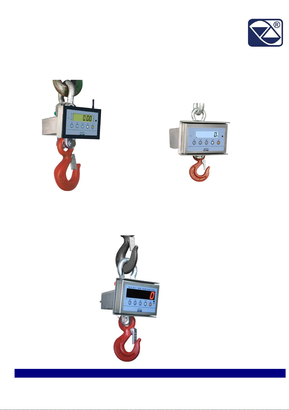
ELECTRONIC CRANE SCALE
MCW-MCWK_03_12.10_EN_U
MCWR2
PROFESSIONAL ‘’INOX
VERSION‘’
MCW PROFESSIONAL
MCWK PROFESSIONAL

MCW-MCWR2-MCWK PROFESSIONAL MCW-MCWK_03_12.10_EN_U
2
INDEX
1 GENERAL INFORMATION ............................................................................................................................................... 3
1.1 INTRODUCTION ........................................................................................................................................................................ 3
1.1.1 Design tion of the m chine nd m nuf cturer d t ........................................................................................................... 3
1.1.2 Premises ............................................................................................................................................................................ 3
1.1.3 Symbols.............................................................................................................................................................................. 4
1.1.4 Gener l precepts ................................................................................................................................................................ 5
1.1.5 Destin tion of use ............................................................................................................................................................... 5
1.1.6 Typic l CE conformity decl r tion ...................................................................................................................................... 6
1.1.7 M rkings ............................................................................................................................................................................. 7
1.1.8 Periodic metrologic l verific tion ...................................................................................................................................... 10
1.1.9 Directives nd reference norms ....................................................................................................................................... 10
1.2 TECHNICAL FEATURES OF THE WEIGHING SYSTEM ........................................................................................................ 11
1.2.1 M in components ............................................................................................................................................................. 11
1.2.2 Cr ne sc le dimensions ................................................................................................................................................... 14
1.2.3 Size of sh ckles nd hooks .............................................................................................................................................. 17
1.2.4 Electronic device fe tures ................................................................................................................................................ 18
1.2.5 Lo d cell fe tures ............................................................................................................................................................. 19
1.2.6 Indic tor environment l fe tures ...................................................................................................................................... 19
1.2.7 Remote control: keys nd comm nds .............................................................................................................................. 20
1.2.8 R dio module fe tures (only for model with r dio module) .............................................................................................. 20
1.3 GENERAL SAFETY NORMS ................................................................................................................................................... 21
1.3.1 L ws nd n tion l norms ................................................................................................................................................. 21
1.3.2 Gener l w rnings ............................................................................................................................................................. 21
1.3.3 Org nis tion l me sures of the user comp ny ................................................................................................................ 22
1.3.4 Indic tions nd w rnings reg rding the cr ne sc le ........................................................................................................ 23
1.3.5 Indic tions nd b ns for working in s fe conditions ......................................................................................................... 24
1.3.6 Environment l conditions ................................................................................................................................................. 24
2 USER MANUAL .............................................................................................................................................................. 2
2.1 USER ........................................................................................................................................................................................ 2
2.1.1 Profession l fe tures ........................................................................................................................................................ 25
2.1.2 Loc tion ............................................................................................................................................................................ 25
2.1.3 Clothing nd equipment ................................................................................................................................................... 25
2.2 DESCRIPTION OF THE MACHINES AND CONTROLS ......................................................................................................... 26
2.2.1 Power supply – St rt-up – Switch-off .............................................................................................................................. 26
2.2.2 Front p nel keys nd indic tors ....................................................................................................................................... 27
2.2.3 Front p nel keys nd indic tors ....................................................................................................................................... 28
2.2.4 Symbols on the LCD displ y(MCW) ................................................................................................................................. 30
2.3 BASIC FUNCTIONS ................................................................................................................................................................. 32
2.3. 1 Functioning with remote control ...................................................................................................................................... 32
2.4 FUNCTIONING ......................................................................................................................................................................... 33
2.4.1 Quick reference ................................................................................................................................................................ 33
2.4.2 Functioning modes ........................................................................................................................................................... 34
3 TECHNICAL INFORMATION .......................................................................................................................................... 3
3.1 PACKAGING, TRANSPORT, HANDLING, STORAGE, AND INSTALLATION ...................................................................... 3
3.1.1 P ck ging......................................................................................................................................................................... 35
3.1.2 Tr nsport, h ndling, stor ge ............................................................................................................................................ 35
3.1.3 Inst ll tion ........................................................................................................................................................................ 36
3.2 MAINTENANCE AND CHECKS ............................................................................................................................................... 36
3.2.1 D ily monitoring ................................................................................................................................................................ 36
3.2.2 Regul r M inten nce ....................................................................................................................................................... 37
3.2.3 M inten nce registry ........................................................................................................................................................ 40
3.2.4 Cle n ................................................................................................................................................................................ 41
3.2.5 Repl cing the remote control b tteries ............................................................................................................................ 41
3.2.6 Electronic cr ne sc le b ttery: instructions nd rech rge ................................................................................................ 42
3.2.7 The b ttery rech rge by option l kit ................................................................................................................................. 43
3.3 DECOMMISSIONING AND DISPOSAL ................................................................................................................................... 46
4 WARRANTY .................................................................................................................................................................... 47

MCW-MCWR2-MCWK PROFESSIONAL MCW-MCWK_03_12.10_EN_U
3
1 GENERAL INFORMATION
1.1 INTRODUCTION
Dear Customer,
We thank you for choosing a Dini Argeo product and we invite you to carefully read this manual before carrying out any
operation on the instrument that you have purchased.
It is of utmost importance that the main checks and maintenance or repair interventions be recorded in the appropriate
section of the booklet.
Therefore we kindly ask you to carefully keep this booklet and present it to the manufacturer Dini Argeo or to the
authorised reseller each time that it is necessary to carry out maintenance, repair, or replace spare parts accessories on
the instrument.
NOTE:
This m nu l is n integr l p rt of the instrument nd if sold, it must be given to the new owner.
1.1.1 Designation of the machine and manufacturer data
The “MCW/MCWK” instrument is n electronic weighing device, to be considered s lifting ccessory, suit ble for use
on overhe d cr nes, or on simil r lifting devices.
It is composed by tension lo d cell, n electronic device to me sure nd indic te the weight, sh ckle connecting the
hook of the lifting me ns nd the lo d cell, nd n eye hook for the connection between swivel hook nd lo d lifting
devices.
Norm lly the remote comm nd of the me suring instrument t kes pl ce through n infr red r y system.
It is possible lso to use r dio devices both for the remote comm nds s well s for the d t tr nsmission (RF).
With reg rd to the lo d cell nd its components sizes, the equipment c n h ve different m ximum c p cities; in
kilogr ms there re: 150, 300, 600, 1500, 3000, 6000, 6500, 8000.
The instrument c n be suit ble for use with third p rties (M) or for intern l use.
The complete identific tion will then be:
MCW + (150 or 300 or 600 o 1500 or 3000 or T6) + (M – only if for use with third) or MCW + (150 or 300 or 600 or 1500 or
3000 or T6) if the instrument would be suit ble t n intern l us ge.
MCWK6 (3000 kg or 6000 kg) + (M – only if for use with third) or MCWK6 if the instrument would be suit ble t n intern l
us ge.
MCWK8 (6000 kg or 8000 kg) + (M – only if for use with third) or MCWK8 if the instrument would be suit ble t n intern l
us ge.For more inform tion see p r gr ph “MARKINGS”.
This m nu l t kes into consider tion the v rious types.
MANUFACTURER’S DATA:
DINI ARGEO srl
– vi dell Fisic , 20 - 41042 Spezz no di Fior no (MO) - It ly
Tel. 0536-843418 F x 0536-843521 E-m il info@dini rgeo.com web www.dini rgeo.com
1.1.2 Premises
The purpose of this m nu l is for the user to know ll the fund ment l norms nd criteri for the inst ll tion, the correct
use nd for c rrying out the correct m inten nce of the purch sed instrument.
Therefore:
•This m nu l cont ins ll the sc le’s user instructions nd the necess ry knowledge for its correct nd s fe use.
•This m nu l supplies the useful indic tions for the correct functioning nd m inten nce of the rel tive electronic cr ne
sc le; it is therefore import nt to p y c reful ttention nd refer to ll those sections which illustr te the simplest nd
s fest w y to oper te.
•This public tion, or ny p rt of it, c n be reproduced without the written uthoris tion by the M nuf cturer.
PS: The person responsible for the use of the weight indicator must make sure that all of the safety rules in force
in the country of its use should be applied, to guarantee that the equipment is used in conformity with the use for
which it is destined and avoid any dangerous situation for the users.
MCW-MCWR2-MCWK PROFESSIONAL MCW-MCWK_03_12.10_EN_U
4
Any attempt of tampering or modifying the instrument by the user or non authorised personnel, or improper use,
or different than what is foreseen in this manual, will relieve the Manufacturer from all responsibility in the case
of damages caused by people or things.
1.1.3 Symbols
Ple se find below the symbols in the m nu l which rec ll the oper tor’s ttention, in reg rds to the v rious d nger levels.
The d nger levels will be subdivided in four cl sses of import nce:
Besides the symbols of the four different d nger levels, other symbols used, will be shown:
- in the m nu l to rec ll the ttention of the re der;
- on the instrument to rec ll the ttention of the user.
Conforms to the st nd rds of the Europe n Union.
Identifies the Cl ss Of Precision defined by the OIML to represent 3000 divisions
“
TECH.MAN.REF.
”
me ns th t n dv nced function is being described (therefore for the technic l personnel) which
will be further expl ined in the corresponding technic l m nu l.
The crossed-out wheeled bin on the product me ns th t t the product end of life, it must be t ken
to sep r te collection or to the reseller when new equiv lent type of equipment is purch sed. The
dequ te differenti ted refuse collection in h ving the product recycled helps to void possible
neg tive effects on the environment nd he lth nd supports the recycling of the m teri ls of which
the equipment is m de. The unl wful dispos l of the product by the user will ent il fines foreseen
by the current regul tions.
It is forbidden to h lt or tr nsit under suspended lo d.
I
n c s
e of
n
ccident
,
c
oncept or procedure which
c n
c use d m ges to the instrument or m teri ls or dj cent to
it, if it does not c rry out ccur tely.
CAUTION!!
Concept or procedure which, if not c rried out
ccur tely, c n c use h rsh person l injuries or
d m ges to the instrument in c se of ccident.
CAREFUL!!
Concept or procedure which, if not c rried out
ccur tely, c uses the d nger or h rsh person l injuries
in c se of ccident.
DANGER!!
WARNING: Import nt inform tion or procedure which
dvises the oper tor reg rding the optim l use of the system
nd on ll the connected work modes.

MCW-MCWR2-MCWK PROFESSIONAL MCW-MCWK_03_12.10_EN_U
5
1.1.4 General precepts
The w rnings shown in this m nu l rec ll the ATTENTION OF THE OPERATOR in reg rds to inform tion or procedures
which dvise the best use of the equipment in order to:
-work s fely;
-lengthen the dur tion nd function lity;
-void the d m ges or loss of the progr mming;
-optimise the work by t king into ccount the metric nd s fety norms in force in the country where it is used;
For the indic tions nd w rnings for working in s fety conditions see the “GENERAL SAFETY NORMS” section.
1.1. Destination of use
The “MCW/MCWK” instrument is non utom tic weighing device, to be considered s lifting ccessory, suit ble to be
used on cr nes, or on simil r lifting devices.
In reg rds to the weight me surement it is possible to identify the following oper ting conditions:
-use for determining the weight for commerci l tr ns ctions.
-use for determining the weight for intern l use.
The n me of the device models suit ble to be used for commerci l tr ns ctions re distinguished by fin l letter M nd
APPROPRIATE MARKINGS (see section “MARKINGS”).
The device c n be used only in ordin ry work environments. For further det ils see section “ENVIRONMENTAL
CONDITIONS”.
The cr ne sc le is to be considered sc le, nd therefore should only be used s weighing instrument.
Therefore ny improper use, or different th n wh t is foreseen in this m nu l, will relieve the M nuf cturer of
ll responsibilities in c se of d m ges, direct or indirect, c used to people or things.
MCW-MCWR2-MCWK PROFESSIONAL MCW-MCWK_03_12.10_EN_U
6
1.1.6 Typical CE conformity declaration
DICHIARAZIONE DI CONFORMITA’
DECLARATION OF CONFORMITY
KONFORMITÄTSERKLÄRUNG
DÉCLARATION DE CONFORMITÉ
DECLARACIÓN DE CONFORMIDAD
F bbric nte:
M nuf cturer:
Hersteller:
F bric nt:
F bric nte:
DINI ARGEO srl
Din mometro elettronico modello:
Electronic cr ne sc le model:
Electronische Kr nw ge Modell:
Din momètre électronique modèle:
G ncho pes dor electrnico modelo:
MCW / MCWR2/MCWK
Anno di costruzione:
M nuf cturing ye r:
Herstellungsj hr:
Année de f bric tion:
Año de construcción:
Numero di serie:
Seri l number:
Seriennummer:
Numéro de série:
Número de serie:
E’ conforme lle direttive:
-Conforms to the directives: / Konform mit folgenden richtlinien ist: / Est conforme ux directives: / Es conforme l s
directiv s:
2004/108/CE - Compatibilità Elettromagnetica
-Elecrtom gnetic Comp tibility / Elektrom gnetische Komp tibilität /
-Con riferimento alle norme armonizzate:
-With reference to these h rmonised norms: / Mit Bezug uf die Normen: / En référence ux normes h rmonisées: / Con
referenci l s norm s rmoniz d s:
(CEI EN 61000-6-2 / 2006 ; CEI EN 61000-6-4 / 2007 ; CEI EN 61326-1 / 2007 ; CEI EN 011 / 2009)
2006/42/CE - Macchine
-M chines / M schinen / M chines / Máquin s
Dichiara inoltre che:
Decl res lso th t: / Der Hersteller erklärt uβerdem, d ss: / Décl re ég lement que: / Decl r t mbién que:
-La persona autorizzata a costituire il fascicolo tecnico presso la sede del fabbricante è la Direzione Tecnica.
The person uthorised to compose the technic l file t the premises of the m nuf cturer is the Technic l M n gement. /
Die utorisierte Person, die die technischen Dokumente im Firmensitz des Herstellers verw ltet, ist d s technische
M n gement. / L personne utorisée à constituer le dossier technique chez l siége du f bric nt est le directeur
technique. / L person utoriz d constituir el expediente técnico en l sede del f bric nte es l Dirección Técnic .
D t /D te/D tum
Firm /Sign ture/Unterschrift

MCW-MCWR2-MCWK PROFESSIONAL MCW-MCWK_03_12.10_EN_U
7
1.1.7 Markings
On the equipment one will find l bel in which there re shown the metrologic l nd technic l inform tion s well s the
rel tive CE m rking of the instrument.
M rking for devices suit ble for intern l use:
In which:
1 Comp ny n me nd f bric tion st tus
2 N me of the m chine
3 N me of the m chine model nd the type of inst lled electronic device
4 Seri l Number (sn)
5 CE M rkings
6 Power supply volt ge
7 Symbol of the dumpster: indic tes th t t the end of its useful life the product must be disposed in the ppropri te
w ste collection bins
8 Instrument’s precision cl ss
9 Me suring field:
M x= m ximum c p city or full r nge of the instrument;
Min= minimum weigh. Weighing ccur cy is not gu r nteed below this v lue;
e= division v lue
10 Sp ce reserved for the CE type pprov l certific te number
11 Building ye r of the m chine
For no re son the d t or closing nd leg lis tion se ls on the instrument’s pl te, must be modified or removed. In
c se of t mpering or remov l of this inform tion, the w rr nty of the instrument ce ses, nd the m nuf cturing
comp ny is rele sed from ny eventu l d m ge, direct or indirect, c used to people or to things.
THE LABELS ARE OF THE ADHESIVE TYPE, WHICH DETACH THEMSELVES WHEN DESTROYED.
CAUT
ION
!!
1
4
3
7
6
8
2
10
9
11

MCW-MCWR2-MCWK PROFESSIONAL MCW-MCWK_03_12.10_EN_U
8
M rkings for devices suit ble for commerci l tr ns ctions:
In which:
1 Comp ny n me nd f bric tion st tus
2 N me of the m chine
3 N me of the m chine model nd the type of inst lled electronic device
4 Seri l Number (sn)
5 CE M rkings
6 Sp ce reserved for the number of the notified body
7 Conformity m rking (instrument subject to metrologic l check)
8 Power supply volt ge
9 Symbol of the dumpster: indic tes th t t the end of its useful life the product must be disposed in the ppropri te
w ste
collection bins
10 Sp ce reserved for the CE type pprov l certific te number
11 Instrument’s precision cl ss
12 Me suring field:
M x= m ximum c p city or full r nge of the instrument;
Min= minimum weigh. Weighing ccur cy is not gu r nteed below this v lue;
e= division v lue
13 Building ye r of the m chine
3
1
6
4
10
7
11
8
9
13 12
2

MCW-MCWR2-MCWK PROFESSIONAL MCW-MCWK_03_12.10_EN_U
9
M rkings on the lo d cell:
SBX model v il ble only for cr ne sc les with c p city below 1500 kg (MCW150R2, MCW150MR2, MCW300R2,
MCW300MR2, MCW600MR2, MCW600R2, MCW1500R2 nd MCW1500MR2.
In which:
1 CE m rking
2 N me of the series or model of the lo d cell
3 Seri l number (sn)
4 M ximum useful lo d (m ximum c p city)
5 With the issuing of the July 22nd, 2005 nr. 151 decree-l w, rel tive to the Europe n Directive 2002/96/EC in reg rds to
the W ste Electric l nd Electronic Equipment (known s WEEE), the rel tive m nuf cturers re c lled to intervene
nd m n ge the life cycle end of their introduced products. All the WEEE products must h ve impressed n e sily
visible nd undelet ble crossed-out dumpster. Therefore the m nuf cturers must offer ll the instruments necess ry
for correct dispos l of this equipment.
6 Test Certific te issued by OIML Notified Body.
1
2
3
4
1
2
3
4
6

MCW-MCWR2-MCWK PROFESSIONAL MCW-MCWK_03_12.10_EN_U
10
1.1.8 Periodic metrological verification
For ll weighing instruments used in commerci l tr ns ctions, it must be scert ined th t the metrologic l fe tures nd
the me surement reli bility re kept in time. A periodic metrologic l verific tion is, therefore compulsory; the periodicity
nd the verifying person depend on the l ws / regul tions of the country in which one is oper ting.
1.1.9 Directives and reference norms
List of the EC directives t ken into reference:
-2009/23/EC (Non utom tic weighing instruments)
-2004/108/EC (Electrom gnetic comp tibility)
-2006/95/EC (Low Volt ge)
-2006/42/EC (M chines)
-1999/5/EC (R dio equipment); only version with r dio module
-2002/95/EC ; 2003/118/EC ; 2002/96/EC ( RoHS nd WEEE )
List of norms or other documents t ken into reference:
-FEM1.001
-CEI EN 61000-6-2 / 2006
-CEI EN 61000-6-4 / 2007
-CEI EN 61326-1 / 2007
-CEI EN 55011 / 2009
-1999/519/EC recommend tion (only version with r dio module)
-ETSI EN 301489-3 1.4.1 version (only version with r dio module)
-ETSI EN 300220-2 2.1.1 version (only version with r dio module)

MCW-MCWR2-MCWK PROFESSIONAL MCW-MCWK_03_12.10_EN_U
11
1.2 TECHNICAL FEATURES OF THE WEIGHING SYSTEM
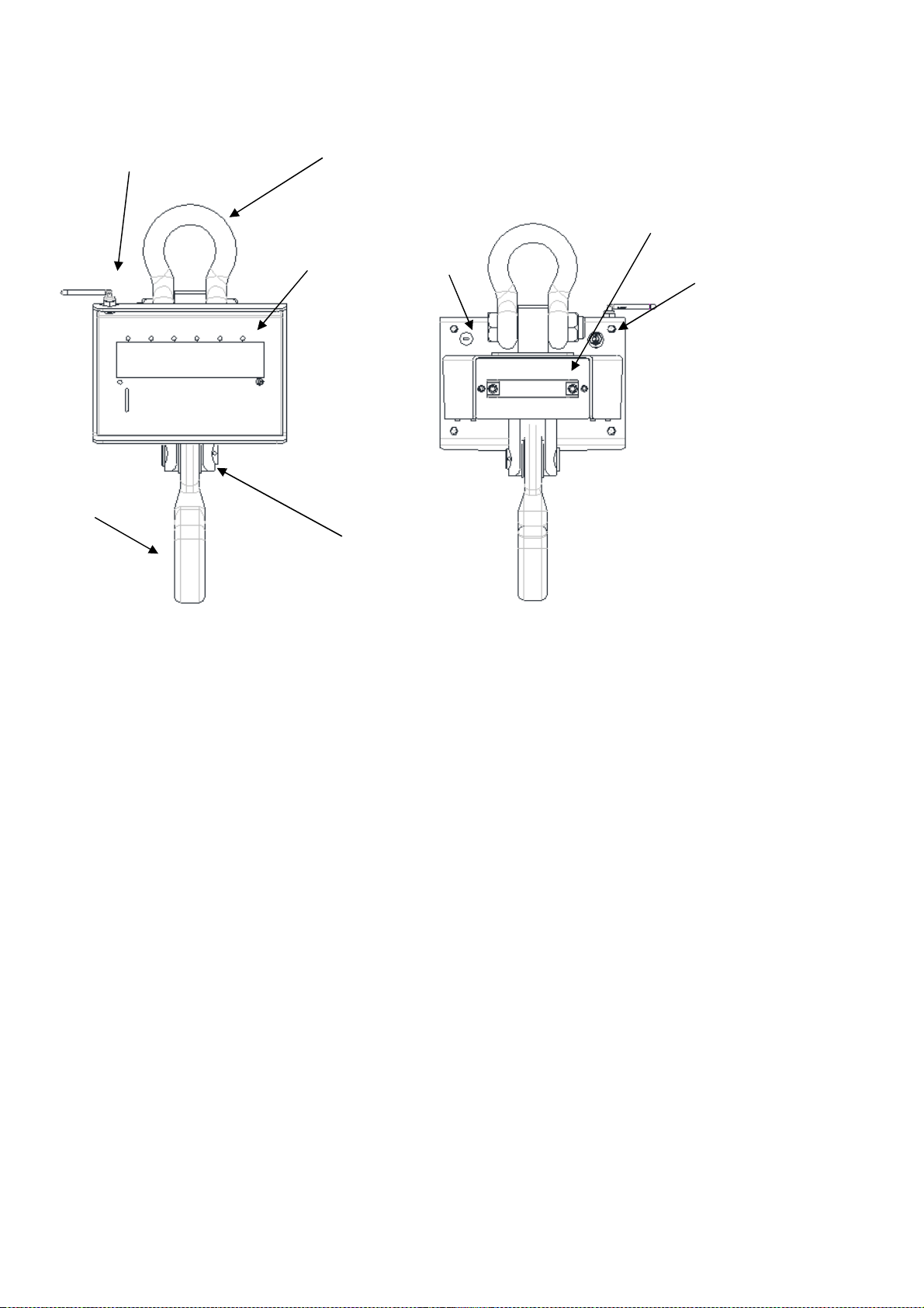
1.2.1 Main components
The “MCW/MCWK” instrument is n electronic weighing device. In order to better underst nd this product, ple se find
below the m in components which re p rt of this m chinery.
MCW PROFESSIONAL:
MCWR2 PROFESSIONAL (INOX VERSION):
MCWK PROFESSIONAL IN ACCIAIO INOX
F1 F2
A
B
D
C
E
F4
A
B
C
D
E
F2
F1
F3
MCW-MCWR2-MCWK PROFESSIONAL MCW-MCWK_03_12.10_EN_U
12
A: body in which there is the tension lo d cell;
B: sh ckle for connection between the lifting device hook nd the lo d cell;
C: eye hook to connect the swivel body to the lifting devices;
D: electronic device for converting the sign l coming from the tr nsducer into weight unit, with me surement displ y,
nd comm nd nd djustment systems;
E: hole predisposed for the outlet of the ntenn (the version with r dio module);
F1: hole prep red for RS232 seri l connection to ny extern l devices (hole is protected by st inless steel c p screw
thre ded);
F2: Connector for connecting to extern l power supply through "j ck";
F3: Integr ted therm l printer, upon request (only for the "MCWR2").
F4: Centering w shers for the lower hook (only for the MCWK8, MCW3000 nd MCWT6 models). These re essenti l
for the correct functioning of the cr ne sc les; without these w shers, the lower hook will not m int in the centr l
position nd the instrument will show n incorrect weight.
In MCW/MCWK electric cr ne sc le, power is supplied by rech rge ble 6 V- 4,5 Ah to be inserted into the b ttery box
loc ted on the b ck of the equipment.
E
A
B
C
D
F1 F2
F4

MCW-MCWR2-MCWK PROFESSIONAL MCW-MCWK_03_12.10_EN_U
13
G: Are the b ttery box nd the rel tive w y of insertion in the electronic cr ne sc le MCW.
H: is the insertion slot in which you insert the b ttery box. The slot is loc ted on the b ck of the instrument.
For more inform tion concerning the b ttery nd its fe tures, see p r gr ph “ELECTRONIC CRANE SCALE BATTERY:
INSTRUCTIONS AND RECHARGE”
.
G
H

MCW-MCWR2-MCWK PROFESSIONAL MCW-MCWK_03_12.10_EN_U
14
1.2.2 Crane scale dimensions
MCW PROFESSIONAL:
DIMENSIONS EXPRESSED IN mm
MODEL A B C D E F G H
MCW3000 450 187 34 260 55 240 58 38
MCW6T 450 187 34 260 55 240 58 45
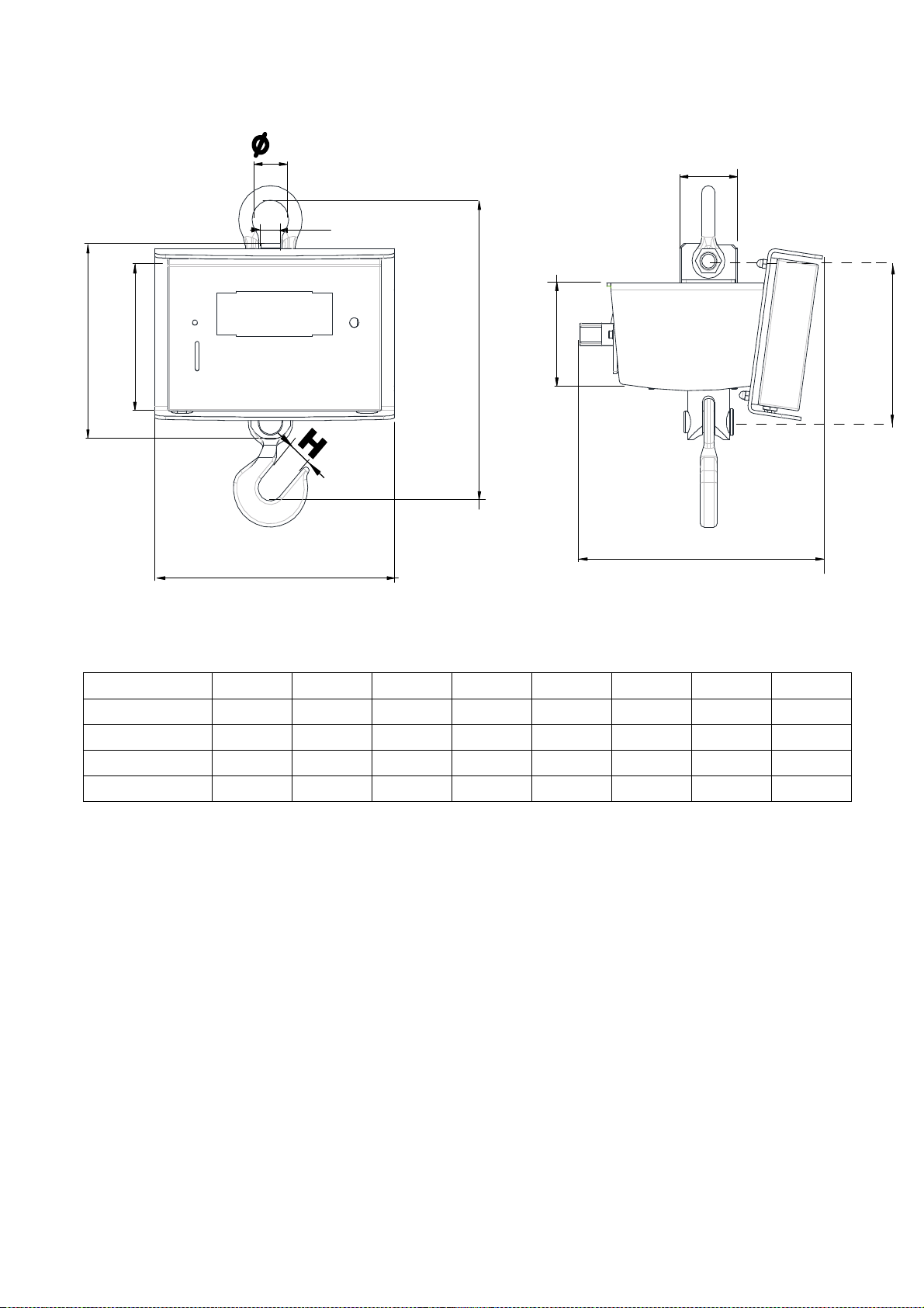
MCW-MCWR2-MCWK PROFESSIONAL MCW-MCWK_03_12.10_EN_U
15
MCWR2 PROFESSIONAL (INOX VERSION):
G
A
B
C
D
120
175
F
290
E
DIMENSIONS EXPRESSED IN mm
MODEL A B C D E F G H
MCW1 0R2 340 180 24 290 70 224 43 30
MCW300R2 340 180 24 290 70 224 43 30
MCW600R2 340 180 24 290 70 224 43 30
MCW1 00R2 340 180 24 290 70 224 43 30

MCW-MCWR2-MCWK PROFESSIONAL MCW-MCWK_03_12.10_EN_U
16
MCWK PROFESSIONAL(VERSIONE INOX):
DIMENSIONI ESPRESSE IN mm
MODELLO A B C D E F G H
MCWK 250 270 44 64 94 74 302 194
MCW-MCWR2-MCWK PROFESSIONAL MCW-MCWK_03_12.10_EN_U
17
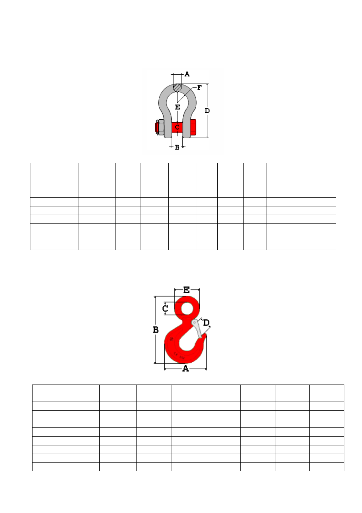
1.2.3 Size of shackles and hooks
The electronic cr ne sc le "MCW" comes with 1 sh ckle nd 1 eye hook. The ccessories supplied h ve the following
ch r cteristics.
SAFETY PIN SHACKLE
MODEL
CAPACI
TY
[Tons]
A
[mm]
A
[inch]
B
[mm]
C
[mm]
D
[mm]
E
[mm]
F
[mm]
c.s
WEIGHT
[kg]
MCW1 0
R2
3,25
16,5
5/8
27,5
20
106
60
22
6
0,75
MCW300
R2
3,25
16,5
5/8
27,5
20
106
60
22
6
0,75
MCW600
R2
3,25
16,5
5/8
27,5
20
106
60
22
6
0,75
MCW1 00
R2
3,25
16,5
5/8
27,5
20
106
60
22
6
0,75
MCW3000
3,25
16,5
5/8
27,5
20
106
60
22
6
0,75
MCWT6
6,5
22
7/8
37
25
146
84,5
29
6
1,87
MCWK6
6,5
22
7/8
37
25
146
84,5
29
6
1,87
MCWK8
9,5
28
1’’1/8
46
33
185
108
37
6
3,58
MATERIAL Bonified 6-degree highly resist nt steel
PIN RAL 3001 red pin with metric thre ding
EYE HOOK
MODEL
CAPACIT
Y
[Tons]
A
[mm]
B
[mm]
C
[mm]
D
[mm]
E
[mm]
WEIGHT
[kg]
MCW1 0
R2
3,20
103
163
32
33
62
0,91
MCW300
R2
3,20
103
163
32
33
62
0,91
MCW600
R2
3,20
103
163
32
33
62
0
,91
MCW1 00
R2
3,20
103
163
32
33
62
0,91
MCW3000
3,20
103
163
32
33
62
0,91
MCWT6
8
166
264
51
47
101
3,95
MCWK6
8
166
264
51
41
101
3,95
MCWK8
8
166
264
51
41
101
3,95
MATERIAL H rdened lloy steel.
FINISH R w or red p inted.

MCW-MCWR2-MCWK PROFESSIONAL MCW-MCWK_03_12.10_EN_U
18
1.2.4 Electronic device features
PROTECTION DEGREE IP 67
POWER SUPPLY 6 Vdc – 4,5 Ah rech rge ble intern l b ttery, st nd rd, r nge of
bout 60 hours. 12 Vdc with extern l power supply 100 ÷ 240 V c
(50÷60 Hz)/12 Vdc st nd rd.
MAXIMUM POWER 5 VA.
MINIMUM VOLTAGE PER DIVISION 0.3 µV (Homolog ted instrument); 0.03 µV (non homolog ted
instrument).
DISPLAYED DIVISIONS 10000e, 3X3000e for leg l for tr de use exp nd ble to 800.000
for intern l f ctory use (with minimum sign l coming from the
1,6mV/V cell).
DISPLAY MCW - B cklit 25 mm LCD displ y with 6 digits.
MCWK - 40 mm LED displ y with 6 digits.
RESOLUTION IN COMTAGE 1'500’000 points (with input sign l equ l to 3mV/V).
KEYBOARD W ter resist nt key polyc rbon te membr ne with t ctile
feedb ck.
TARE FUNCTION Subtr ctive on the entire c p city.
AUTO POWER OFF Adjust ble from 1 to 255 minutes of no use, disinsert ble.
LOW BATTERY WARNING "Low b t" shown on the displ y.
MEASUREMENT UNIT AVAILABLE g= gr ms, kg= kilogr ms, t= tons, Lb= pounds.
IN CALIBRATION PHASE
CONTAINER Sturdy st inless steel, g inst dust nd spl shes.
POWER OF LOAD CELLS 5Vdc ± 5%, 120mA (m x 8 lo d cells 350 Ohm).
I/O SECTION - 1 RS232/TTL input/output
- 1 RS232/input/output
Configur ble for connection to PC/PLC, WEIGHT REPEATER or.
PRINTER.
THEORETICAL LIFE
If the instrument is regul rly m int ined nd if the user instructions
shown in this m nu l re c rried out, the instrument will tt in
theoretic l life of 5 ye rs; the d t is function of use
is subject to ch nge ccording to udits by the m nuf cturer.
For further det ils, see section “MAINTENANCE AND
VERIFICATIONS”.
THE PARTS OF THE INSTRUMENT CONTAINING DANGEROUS ELECTRICAL TENSION ARE ISOLATED AND
INACCESSIBLE TO THE USER UNLESS IT HAS BEEN DAMAGED, OPENED, OR ALTERED.

MCW-MCWR2-MCWK PROFESSIONAL MCW-MCWK_03_12.10_EN_U
19
1.2. Load cell features
The lo d cell is of the str in g uge type, with temper ture compens tion.
The m in technic l fe tures re:
-
Precision and repeatability conform to the OIML R60 recommendation.
-
Precision: 0,8% of the ull Scale capacity ( .S.).
-
High precision and repeatability.
-
Maximum number of load cell divisions: nLC = 3000.
-
Sensitivity: 2mV/V +/-10%.
-
1000 Ohm input resistance.
-
1000 Ohm output resistance.
-
Nominal load creep after 4 hours: 0,03% full range.
-
Thermal compensation: -10°C / +40°C.
-
oreseen life: if the cell is not subject to knocks and/or overloads and is regularly submitted to
maintenance, will attain a theoretical life from 3 to 5 years.
1.2.6 Indicator environmental features
Environment l oper ting fe tures:
OPERATING TEMPERATURE From -10 to +40°C.
RELATIVE HUMIDITY From 10 to 85 % without condens tion

MCW-MCWR2-MCWK PROFESSIONAL MCW-MCWK_03_12.10_EN_U
20
1.2.7 Remote control: keys and commands
Along with the “MCW” electronic cr ne sc le, n infr red remote control is supplied in which it is possible to repe t the
keybo rd functions. Option lly is possible to h ve 6-key r dio remote control.
The type of remote control to be used must be selected in the Setup environment, in the << ir.ConF >> step.
NOTE: The infrared remote controls are for indoor use only.
The functioning instructions re described in section “FUNCTIONING WITH REMOTE CONTROL”.
1.2.8 Radio module features (only for model with radio module)
The r dio module version llows communic ting in r dio frequency with eventu l extern l devices (PC, printer or weight
repe ter); it is fitted with two multipoint r dio frequency modules; one is inst lled on the me surement device nd the
other on the remote unit. The remote modules c n be inserted inside the devices, or fitted with their own w tertight
cont inment box nd connected by c ble.
The multi ch nnel r dio module functions in frequency b nd, without need of license.
SPECIFICATIONS:
POWER SUPPLY 5-12Vdc 100mA m x
OPERATING TEMPERATURE From -10 to +40 °C.
TIMING Power Up Sequence: 135 ms
Enter in Seri l St nd-by: 3.2 ms
W ke Up from Seri l St nd-by: 5.5ms
MAXIMUM POWER 25mW
WORK FREQUENCY From 868 to 870 MHz
NUMBER OF CHANNELS Up to 52
RADIO TRANSMISSION SPEED Up to 38.4 kbps
SERIAL TRANSMISSION SPEED Up to 19.2 kbps
INPUT/OUTPUT 1 RS232 PORT on AMP connector or 1 USB port (with 1m long
USB
c ble fitted), depending on the model.
FUNCTIONING DISTANCE, IN APPROPRIATE CONDITIONS Up to 70m indoors, up to 150m outdoors
CONTAINER Box in PVC (depending on the model)
ANTENNA Swivelling nd inclin ble
NOTE:
For details regarding the configurations and use of the radio module contact the Dini Argeo Assistance Centre.
The device manual can be downloaded from the www.diniargeo.com internet web site or requested to the
Assistance Centre.
Do not press the keys with h rd nd/or pointed objects; only use fingers.
CAUTION!!
This manual suits for next models
2
Table of contents
Other Dini Argeo Scale manuals

Dini Argeo
Dini Argeo T Series User manual

Dini Argeo
Dini Argeo HLD Series User manual

Dini Argeo
Dini Argeo APM User manual

Dini Argeo
Dini Argeo MCWN Series Operating instructions

Dini Argeo
Dini Argeo DGT100 User manual

Dini Argeo
Dini Argeo MCW Guide

Dini Argeo
Dini Argeo TPW Series Operating instructions

Dini Argeo
Dini Argeo ALP User manual

Dini Argeo
Dini Argeo TPW E-FORCE Instruction Manual


