- 8 -
M
TEST COMM
WARNING- ForinstallationinHazardousAreas,i.e.
areaswith danger offire and/orexplosion, priortomaking
electrical connections, ensure compliance with safety
informationonthe SafetyMarkingplate.Failure tocomply
with this warning can result in fire or explosion.
Signal terminals are located in a separate compartment of the
secondary unit housing. The housing incorporates two con-
nection ports for cable glands or conduit fittings. They are
protected with a temporary plastic plug for transit purpose
whichshouldbereplacedwithasuitablepermanentpluginthe
unusedport. Connectionscanbemadebyremovingthecover
(indicatedinFig.7);firstscrewdown thelockingscrewlocated
below the cover, using a 3 mm Allen Key.
WARNING - For Hazardous Areas installations,the
connectionof cablesand conduitsto thetransmittershall
be made in accordance with the requirements of the
relevanttypeofprotection.Cablesandcable-glandsmust
be in accordance with the type of protection.
Unused openings for connection shall be closed with
blanking elements suitable for the relevant type of
protection. With the exception of intrinsically safe
transmitters, the means provided for this shall be such
that the blanking element can be removed only with the
aid of tools. The blanking elements must be certified for
thetypeofprotection.Seestandardseither EN60079-14
or IEC 79-14. The transmitter connections must also
guarantee the degree of protection of the transmitter
enclosure, e.g. IPxx according to EN 60529 standard (or
IEC529).See alsotheAddendum for"IP"protection (and
Ex Safety) which is part of this instruction manual.
Thesignalcableshould beconnectedto theterminalsmarked
respectively (+) and (-). If an internal output meter - either with
analog or digital indication - is installed, it should be removed
inordertomaketheconnection,simplybypullingitoutfromits
socket. After the connections have been made, reinstall the
output meter. Refer to the Meters Option addendum for
details.
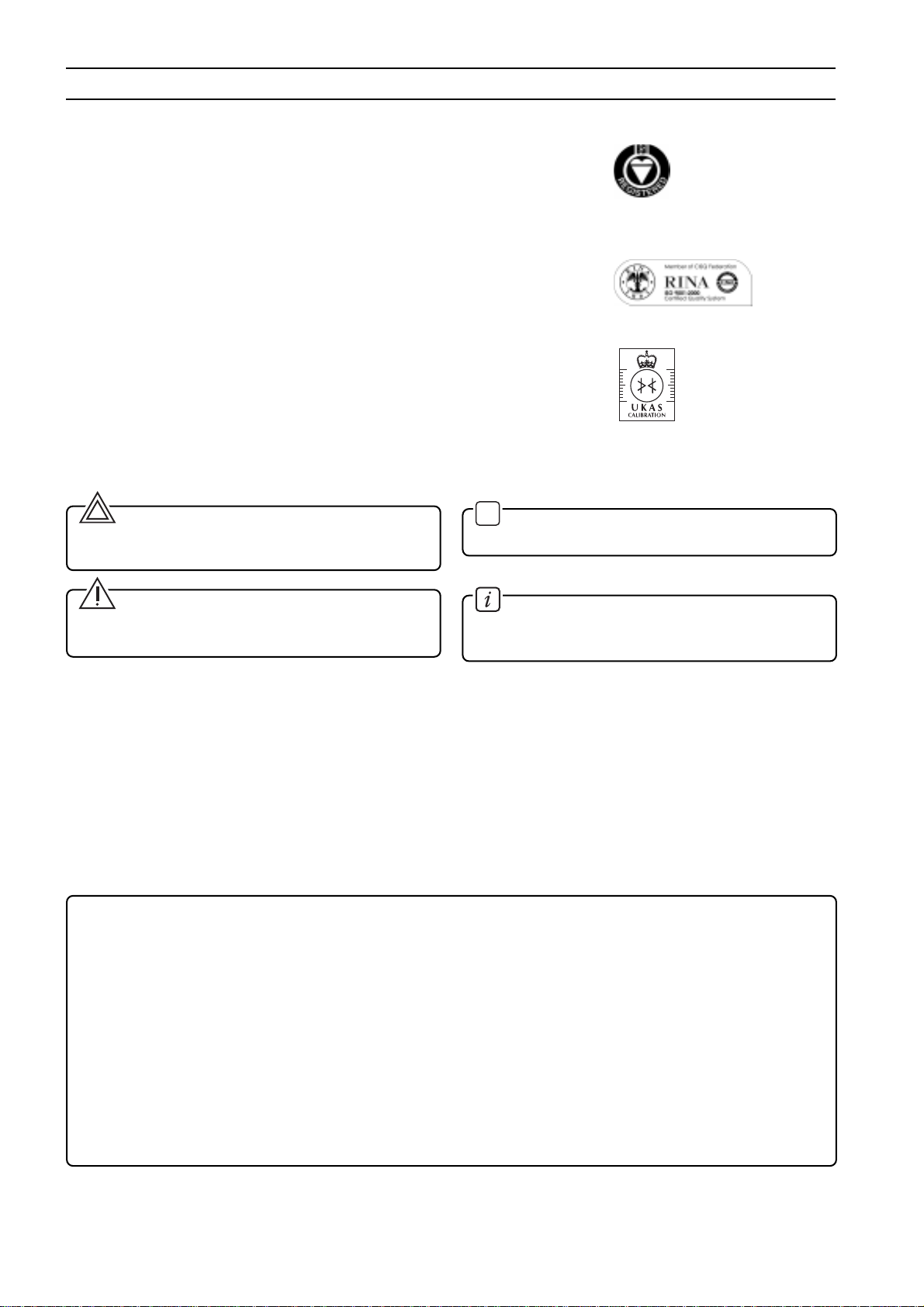
Fig. 7 - Location of the locking screws and terminals
Grub
screw
ELECTRICAL CONNECTIONS
The power to the transmitter is supplied over the signal wiring
and noadditionalwiringis required.Thesignalwiringdoesnot
need to be shielded but the use of a twisted pair is highly
recommended. The cable shield should be grounded in one
side only, to avoid dangerous earth paths.
WARNING - For Hazardous Areas installations,
when the ambient temperature is higher than 70°C, the
cable used for the connections must be suitable for 5°C
above the ambient temperature.
Normal practice is to ground in the control room side, in which
case the field side of the screen should be adequately
protected to avoid contact with metallic objects. Signal wiring
may be ungrounded (floating) or grounded at any place in the
signalloop,butfor intrinsicallysafeinstallations thewiringand
groundingmustfollowthespecificrulesforthistechnique. The
transmitter case may be grounded or ungrounded: a ground
connectionisprovidedinternally(intheterminal compartment)
and externally.
Do not run the signal wiring in close proximity to power cable
or high power equipment; use dedicated conduits or trays for
signal wiring.
CAUTION - Do not connect the powered signal
wiring to the mA signal testing terminals as this could
damage the by-pass diode.
Aftertheconnectionshavebeencompletedchecktheintegrity
of the cover O-ring, screw down the cover and secure it by
unscrewing the safety screw.
CAUTION - Unless absolutely necessary, avoid the
removalonsiteoftheprotectivecoverwhichgivesaccess
totheelectroniccircuitry.Althoughtheelectronicsarefully
tropicalized they should not be subjected to humidity for
long periods.
WARNING - For Hazardous Areas installations, at
least eight (8) threads on each cover must be engaged in
order for the transmitter to meet (flameproof - explosion-
proof) requirements.
Secondary Unit
Cover locking
screws (in the
position
indicated by
the arrows)
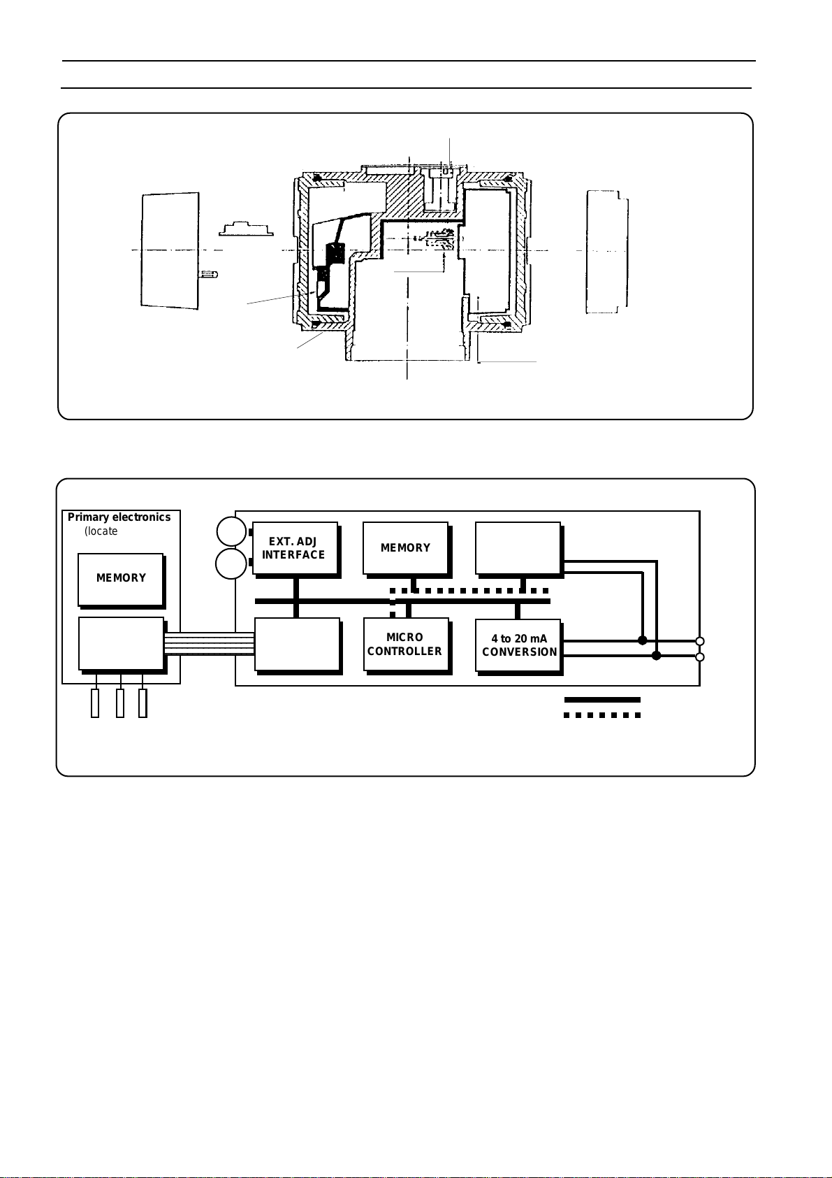
Primary
Unit
Remove
this cover
to access
terminals
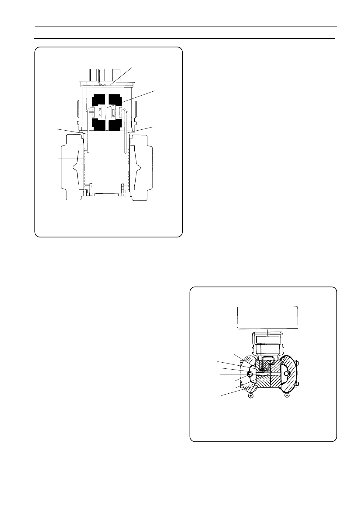
Hand Held Communicator
Terminals
Test Terminals
Output
Meter
Socket
Ground Terminal
Signal Terminals
Fig. 8a - Terminals arrangements
Short
circuit link