Dion F61 User manual
Operator’s Manual
F61 & F63 Rotary Corn Attachment
F61 & F63
Manual No. F6114E957E

2
Manual No. F6114E957E

3
F61 & F63 Rotary Corn Attachment
TO OUR CUSTOMER
We appreciate your condence in DION Farm Equipment and thank you for your trust. In prepar-
ing this manual, we hope we have provided you with a valuable tool for operating and maintaining
this ne machine. Use this manual as your guide. Following the instructions given here will result
in many years of dependable service from your machine.
Your Dealer can give you assistance with parts and specially trained personnel to assist you in
repair and maintenance.
Call your Dealer if you need any assistance or information.
Manual No. F6114E957E

4
Manual No. F6114E957E

5
TABLE OF CONTENTS
SPECIFICATIONS ......................................................................................................................... 6
SERIAL NUMBER LOCATION ...................................................................................................... 7
CHECK LIST ................................................................................................................................. 8
FOREWORD ................................................................................................................................. 9
SAFETY RULES ............................................................................................................................ 11
TRANSMISSION SHAFT OPERATION ............................................................................... 13
STOPPING PROCEDURES ................................................................................................ 13
GUARDS AND SHIELDS ..................................................................................................... 14
SAFETY SIGN LOCATION .................................................................................................. 15
SAFETY SIGN APPLICATION PROCEDURE .................................................................... 16
INSTALLATION ............................................................................................................................. 17
INSTALLATION OF THE CORN ATTACHMENT ON THE FORAGE HARVESTER ............ 17
OPERATING .................................................................................................................................. 22
OPERATING TIPS ............................................................................................................... 22
OPERATING SPEED ........................................................................................................... 22
BOLT TORQUE SPECIFICATIONS ..................................................................................... 22
MEASURING GAUGE ......................................................................................................... 22
LUBRIFICATION ........................................................................................................................... 23
LUBRICATION CHART ........................................................................................................ 23
CHAIN LUBRICATION ......................................................................................................... 24
CONVEYING CHAINS LUBRICATION ................................................................................ 25
DRUM BEARING LUBRICATION ........................................................................................ 25
TIGHTENER ROD LUBRICATION ...................................................................................... 26
GEARBOX LUBRICATION .................................................................................................. 26
ADJUSTMENT- MAINTENANCE .................................................................................................. 27
GROUND CLEARANCE ADJUSTMENT ............................................................................. 27
CONVEYOR CHAIN TENSION ADJUSTMENT .................................................................. 28
CONVEYOR CHAIN STRETCH CHECK ............................................................................. 29
CONVEYOR CHAIN ADJUSTMENT ................................................................................... 31
CHAIN REPLACEMENT ...................................................................................................... 32
CHAIN SYNCHRONIZATION .............................................................................................. 33
INTERMEDIATE CHAIN TENSION ADJUSTMENT ............................................................. 33
KNIFE SECTION REPLACEMENT ...................................................................................... 34
DEFLECTOR-KNIFE REPLACEMENT ................................................................................ 34
STRAIGHTENING UP THE DRUM FINGERS ..................................................................... 35
SAW DRIVE BELT TENSION ADJUSTMENT ...................................................................... 35
DRIVE BELT REPLACEMENT ............................................................................................. 35
DEFLECTOR ADJUSTMENT............................................................................................... 36
FRICTION CLUTCH REPLACEMENT ................................................................................. 36
DRUM ADJUSTMENT ......................................................................................................... 37
SCRAPER ADJUSTMENT ................................................................................................... 38
FREEWHEEL CLUTCH CHECK-UP .................................................................................... 38
MAINTENANCE SUMMARY ................................................................................................ 39
STORAGE ..................................................................................................................................... 40
Manual No. F6114E957E

6
Specications and design are subject to change without notice
and without liability therefore
NOTE: Specications apply to both F61 and F63 models.
IMPORTANT: This manual was written for the operator of both the F61 and F63 Rotary Corn Attachments.
However, please note that all illustrations are of the F61 model only.
WEIGHT ........................................................................ 2500 lbs (1130 kg)
DIMENSIONS :
overall width ................................................................... 117” (297 cm)
length ............................................................................. 75” (191 cm)
height .............................................................................. 50” (127 cm)
SPECIFICATIONS
Manual No. F6114E957E
7
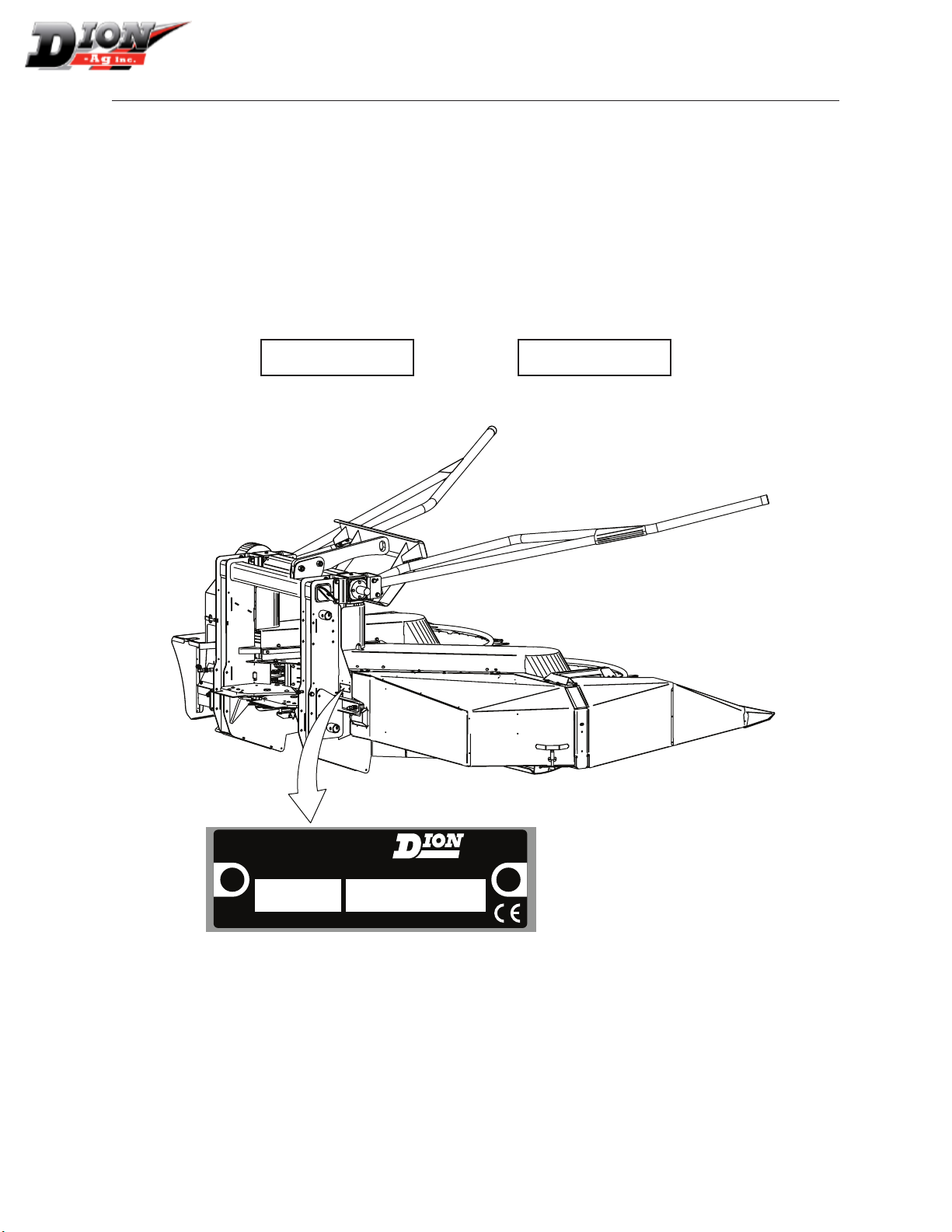
For your convenience, write down in full in this manual both the model and serial numbers of your
machine, as shown on the name plate illustrated below. Always mention both the model and
the serial numbers when ordering parts or regarding any other correspondence referring to your
machine
Write down your number here:
MODEL NO. SERIAL NUMBER
LEFT
REAR
FRONT
RIGHT
MADE IN CANADA
DION-AG INC.
BOISBRIAND QUE.
MODEL NO.
SERIAL NO.
Dion-Ag Inc.
SERIAL NUMBER LOCATION
Manual No. F6114E957E

8
PRE-SEASON CHECKS
Check condition of guards and knives
Check condition of chains and chain guides
Check chain tension and elongation
Check condition and tension of drive belts
Check condition of free wheel clutch (knives)
Look for loose or missing bolts and parts
Make sure no safety decal is missing and make sure they are readable
Check condition of saw teeth
Check condition of drum ngers. Make sure they are solid and straight
Check oil levels on both gearboxes
DAILY CHECKS
Check tension of belts and chains
Clean machine
Lubricate following instructions found in maintenance section
Make sure all guards are in good condition
CHECK LIST
Manual No. F6114E957E

9
TO OUR CUSTOMER
The following pages and illustrations are printed to
help supply you with the knowledge to better ope-
rate and service your F61 or F63 Rotary Corn At-
tachment.
Any piece of equipment needs, and must have a
certain amount of service and maintenance to keep
it in top running condition. We have attempted to
cover all the adjustments required to t most condi-
tions; however, there may be times when special
care must be taken to t a condition.
Study this operator’s manual carefully and become
acquainted with all the adjustments and operating
procedures before attempting to operate your new
equipment. Remember, it is a machine and it has
been designed and tested to do an efcient job in
most operating conditions and will perform in rela-
tion to the service it receives.
If special attention is required for some conditions,
ask your Dion Dealer; his parts and Service Organi-
zation will be glad to help and answer any questions
on operation and service of your new machine.
THIS MANUAL SHOULD REMAIN WITH THE
MACHINE WHEN SOLD
This manual was prepared from the latest product
information available at publication time. The Com-
pany reserves the right to make changes at any time
without notice.
The safety section of your Operator’s manual is in-
tended to point out some of the basic safety situa-
tions which may be encountered during the normal
operation and maintenance of your F61 or F63 Ro-
tary Corn Attachment, and to suggest possible ways
of dealing with these situations. This section is NOT
a replacement for other safety practices featured in
other sections of this book.
WARRANTY INFORMATION
Your Dion Warranty for this machine appears on
your copy of the Retail Purchase Order and War-
ranty Terms and Conditions Statement which you
received from your dealer when you purchased the
F61 or F63 Rotary Corn Attachment.
As indicated on the Retail Purchase Order signed by
you and your dealer, you, the equipment purchaser,
shall assume charges for service calls or transpor-
tation of equipment to and from the location of ser-
vicing Dion dealer.
SAFETY
The safety of the operator is one of the main
concerns in designing and developing a new F61
or F63 Rotary Corn Attachment. Designers built
in as many safety features as possible. However,
every year accidents occur which could have been
avoided by taking a more careful approach to hand-
ling farm machinery and implements.
Read and implement the safety instructions detailed
in the safety section of this manual.
FOREWORD
Manual No. F6114E957E

10
Manual No. F6114E957E

11
SAFETY ALERT SYMBOL
The symbol above calls your attention to instruc-
tions concerning your personal safety. It is found
throughout the manual as well as on the machine to
point out specic hazards and ways to avoid them.
Always follow the instructions to minimize the risk of
personal injury or death.
DANGER, WARNING AND CAUTION
Whenever you see the words and symbols shown
below, used in this manual and on decals, you
MUST take note of their instructions as they relate
to personal safety.
DANGER: Indicates an imminently
hazardous situation that, if not avoided, will
result in DEATH OR VERY SERIOUS INJURY.
WARNING: Indicates a potentially
hazardous situation that, if not avoided,
could result in DEATH OR SERIOUS
INJURY.
CAUTION: Indicates a potentially
hazardous situation that, if not avoided,
may result in MINOR INJURY.
IMPORTANT: The word IMPORTANT is used to
identify special instructions or procedure which, if
not strictly observed, could result in damage to, or
destruction of the machine, process or its surround-
ings.
NOTE: The word NOTE is used to indicate points
of particular interest for more efcient and
convenient repair or operation.
SIGNS
WARNING: DO NOT remove or obscure
Danger, Warning, Caution safety signs or
Instruction signs that are not readable or are
missing. Replacement signs are available
from your Dealer in the event of loss or
damage. The actual location of these Safety
signs is illustrated on pages 15 and 16.
FOLLOW A SAFETY PROGRAM
For proper operation of a corn attachment, you must
be a qualied and authorized operator. To be qual-
ied, you must read and understand the written in-
structions supplied in this Operator’s Manual, have
training, and know the safety rules and regulations
for the job.
Some local regulations specify that no one under
the age of 16 years, for example, may operate pow-
er machinery. This includes tractors. It is your re-
sponsibility to know what these regulations are, and
obey them, in the operating area or situation. These
will include, but are not limited to, the following in-
structions for proper operation.
WARNING: An operator should not use alco-
hol or drugs which can change their alertness
or coordination. An operator on prescription
or “over the counter” drugs needs medical
advice on whether or not he or she can prop-
erly operate machines.
A WORD TO THE OPERATOR
It is YOUR responsibility to read and understand the
safety section in this manual before operating your
tractor. You must follow these safety instructions
that take you step by step through your working day.
In reading this section, you will note that illustra-
tions have been used to highlight certain situations.
Each illustration is numbered and the same number
appears in the text in parenthesis. This number is
placed at the end of the written text that refers to the
illustration.
Remember that YOU are the key to safety. Good
safety practices not only protect you, but also the
people around you. Study the features in this manu-
al and make them a working part of your safety pro-
gram. Keep in mind that this safety section is written
only for this type of machine. Practice all other usual
and customary safe working precautions, and above
all.
REMEMBER - SAFETY IS YOUR RESPONSIBIL-
ITY. YOU CAN PREVENT SERIOUS INJURY OR
DEATH.
WARNING: In some of the illustrations used
in this Operator Instruction Book, panels or
guards may have been removed for clarity.
Never operate the machine without these
components in position. If the removal of
panels or guards is necessary to make a
repair, they MUST be replaced before oper-
ation.
SAFETY RULES
Manual No. F6114E957E

12
• Disengage the PTO and shut off engine before
leaving the operator’s seat for refueling, lubrica-
ting or adjusting the machine.
• Wear appropriate clothing, safety boots or shoes.
Do not operate the machine when visibility is bad,
or during night, in poor lighting.
• When driving on a public road, or on hilly land
you must remove the electrical box ignition key
and put the locking pin in the stop pawl of the
quick-disconnect hitch to prevent unlocking. This
locking pin should also be used for the manual
quick-disconnect hitch.
• Attach a safety chain of at least 20,000 lbs (9071
Kg) capacity for transportation.
• Keep children away from the machine at all times.
Maximum traveling speed of a forage harvester
should not exceed 20 mph (34 km/h).
• Carefully read all safety signs applied on the ma-
chine. If they are damaged, replace them imme-
diately.
• The tractor engine ignition key must be removed
each time the operator leaves the tractor.
• If a feeding or throwing mechanism should be-
come jammed, never attempt to unblock it or re-
move any material when the machine is in motion
or the tractor engine running.
• Never manually feed the rotary corn attachment.
• Never remove guards or make adjustments while
the machine or tractor engine is running.
• Never attempt to check or adjust chains while the
machine is running.
• Keep hands and feet away from the pick-up
chains and the saw.
• Make sure all rotating parts are stopped and the
tractor engine is turned off before cleaning the
machine throat.
• Never park the attachment in the transportation
position. Lower the attachment to the ground rst.
• Before starting the tractor engine, make sure all
guards, shields, and doors are in place and pro-
perly secured and check the machine thoroughly
for possible loose parts or bolts and tighten
them.
• Always pick-up tools after performing any adjust-
ment.
• Never allow riders on any part of a machine.
• Block elevated components before servicing
equipment.
• Never lubricate or clean any part while the ma-
chine or tractor engine is running.
• Keep hands and body out of hitch area when at-
taching towing vehicle.
WARNING: Hydraulic uid under pressure
can penetrate the skin or eyes and cause
serious personal injury, blindness or death.
Fluid leaks, under pressure, may not be vis-
ible. Use a piece of cardboard or wood to
ndleaks.DONOTuseyourbarehand.Wear
safetygogglesforeyeprotection.Ifanyuid
is injected into the skin, it MUST be surgically
removed within a few hours by a doctor fa-
miliar with this type of injury.
• Securely block the wheels from moving before wor-
king on or under the machine.
• Use a lift system with a minimum capacity of
3,000 lbs (1365 kg) to install the attachment on a
forage harvester.
• Never pull a full box behind a forage harvester
when driving on a public road.
• Make sure to meet local regulations regarding
wide loads on public roads.
SAFETY RULES
Manual No. F6114E957E

13
SAFETY RULES
TRANSMISSION SHAFT OPERATION
• POWER-TAKE-OFF DRIVE - Before starting the
tractor engine make sure that the PTO locking de-
vice is properly engaged onto both the tractor and
equipment PTO shafts.
• Never wear loose clothing and keep people, es-
pecially children away from the PTO.
• Do not hook a 1000 RPM tractor on a machine
equipped with a 540 RPM drive and/or a 540 RPM
tractor on a machine equipped with a 1000 RPM
drive.
• Never proceed to the starting of the machine be-
fore making sure all PTO, machine and tractor,
shields are well installed in place.
• The PTO shields should turn freely, be well con-
nected and kept in good condition.
• Never step across any driveline.
• Never use the driveline as a step.
• Keep at least your height away from a rotating
driveline
STOPPING PROCEDURES
No matter what type of machine is being used, it is
extremely hazardous to perform any kind of main-
tenance work while the machine is running. Before
cleaning, adjusting, or greasing, the following pro-
cedures should be followed to stop the attachment:
1. Lower the attachment to the ground.
2. Set the transmission to neutral.
3. Disengage the tractor power-take-off (PTO).
4. Stop the tractor engine.
5. Engage the tractor parking brake.
6. Wait until all rotating parts are totally stopped.
7. Remove the P.T.O. from tractor output shaft.
8. Block all equipment wheels.
DANGER: Rotating driveline contact may
cause serious injury or death.
Manual No. F6114E957E

14
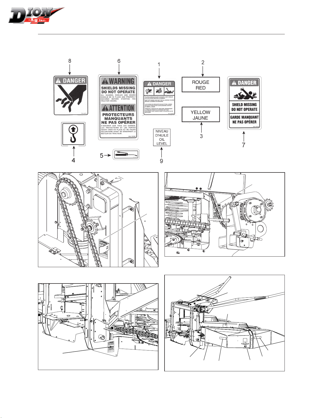
GUARDS AND SHIELDS - FIGURES 1 TO 4
The rotary corn attachment is equipped with guards
and shields wherever an accident is likely to take
place. These guards and shields do not affect the
machine performance. Several safety decals are af-
xed on the machine to remind of potential dangers
Bolted guards cover the driving belts (gure 1).
Figure 1 Drive belt guards (1) and drive chain guard (2)
Hinged guards cover the driving chains (items 2 in
gures 1 and 2).
Figure 2 Drive chain right guard
An hinged guard cover the intermediate chain
(gure 3).
Figure 3 Intermediate chain guard
An hinged guard covers the drive shaft (gure 4).
Figure 4 Drive shaft guard
CAUTION: All guards and shields factory
installed should be in place and maintained
in good condition.
SAFETY RULES
Manual No. F6114E957E
15
SAFETY SIGN LOCATION
IMPORTANT: All safety decals should be in place and maintained in good condition. Decals should be
readable at all times.
6
Figure 5 Safety sign location
6
Figure 6 Safety sign location
6
Figure 7 Safety sign location
tion
4
6528
3
1
1
Figure 8 Safety signs (right-hand side)
Manual No. F6114E957E

16
SAFETY SIGN LOCATION
SAFETY SIGN APPLICATION PROCEDURE
1. The surface should be free from dirt, grease,
earth, or any other foreign material.
2. When the surface is dry, remove a portion of the
backing paper and apply the decal in part and
align its position as per the surrounding parts.
Slowly peel off the remaining backing paper and
apply hand pressure.
3. Press slightly on the surface of the safety sign to
remove all air bubbles.
1
7
9
9
Figure 9 Safety sign location
1
1
8
6
4
9
Figure 10 Safety sign location (left-hand side)
Manual No. F6114E957E

17
INSTALLATION
INSTALLATION OF THE ROTARY CORN
ATTACHMENT ON THE FORAGE HARVESTER
NOTE: Always remove tension on balancing
springs before installing or removing at-
tachment from Forage Harvester.
Make sure the Forage Harvester and the rotary corn
attachment are standing on a at terrain.
The rotary corn attachment is equipped with a sup-
port (gure 11) to lift attachment up for proper in-
stallation. The minimum lifting load must be 3000
lbs (1365 Kg).
1. Attach a chain to the lift support (gure 11).
2. Measure the corn attachment opening (gure
12) and adjust if necessary.
IMPORTANT : If the throat sides on the at-
tachment are bent or damaged, it is neces-
sary to repair them so they will not come in
contact with the feed rolls
3. Slowly move the Forage Harvester toward the
attachment (gure 13), making sure it is well
centered with respect to the connecting pins.
4. Align and adjust the attachment throat sides be-
tween the Forage Harvester sides and the feed
rolls (gure 14).
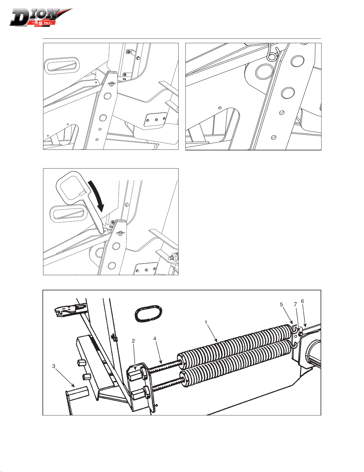
5. When the attachment is set in place on the For-
age Harvester, put the square lock pins and the
safety pins back in place (gures 15 and 16). It
will be necessary to install two oating springs
and to move the bracket in the upper lifting hole.
6. Adjust both balancing springs (gure 17). The
purpose of the balancing springs is to counter-
balance the weight of the attachment either to
slightly touch the ground or ease the attachment
hydraulic lifting to avoid possible obstacles in
the eld.
The tension of these springs must be adjusted to
obtain approximately 80-100 lbs (36-45 Kg) at the
end of the ngers.
Figure 11 Lift support
Figure 12 Adjustment
Figure 13 Move attachment toward Harvester
Manual No. F6114E957E
18
Figure 14 Align
Figure 16 Insert square lock pins
Figure 15 Square lock pin in place
7. Adjust the springs (item 1) by turning the screw
(item 2) sleeves (item 4) with the handle (item
3). Two balancing springs are required to op-
erate your attachment. Bolt the spring bracket
(item 5) on the attaching bar (item 6) as shown.
Tighten well the bolt (item 7) then install both
balancing springs.
8. Adjust the cylinder stroke to prevent the attach-
ment from touching the feed rolls.
INSTALLATION
Figure 17 Balancing springs set-up when using a Rotary Corn attachment
Manual No. F6114E957E

19
INSTALLATION
9. On Gehl, New Holland and Case harvesters, in-
stall the plate (item 2, gure 18) and 2” spring
(item 1, gure 18) on the harveste axle.
1
2
Figure 18 Installing the plate and spring
10. After having tightened the original lifting springs
to the maximum, using a wrench (item 1, gure
19), adjust the spring to obtain 80 to 100 lbs (36
to 45 kg) at the end of the ngers.
1
Figure 19 Adjust spring
11. On JF harvesters, install the 3 springs as shown
in gure 20.
Figure 20 Installing the 3 springs
12. On Dion harvesters, install the rotary corn at-
tachment drive chain (item 1, gure 21). Use
the #60 X 36 3/4” lg (93cm) chain with a #60
connecting link (item 1) or a #80 X 37” chain,
depending on the Forage Harvester congura-
tion.
Figure 21 Installing the drive chain
NOTE: The #80 sprocket is standard on the attach-
ment. As for the #60 sprocket, it must be
specied when machine is ordered.
Manual No. F6114E957E

20
INSTALLATION
13. Adjust the Forage Harvester lifting arms in op-
erating position. Bring the chain underneath the
tightening sprocket (item 2, gure 21) as shown.
Align the driving roll chain. Move the sprock-
et wheel and friction clutch assembly (item 5,
gure 22) on the shaft if necessary. Adjust the
chain to a normal tension, loosen nut (item 4,
gure 22), tighten tightener nut (item 3, gure
22) then tighten nut (item 4, gure 19).
NOTE: On Forage Harvester models prior to 2006,
it will be necessary to cut out a notch in the
Forage Harvester transmission guard (g-
ure 23) or to order a new guard
NOTE: On NH, CASE IH and JF Forage Harvest-
ers, install the PTO to start the machine. Figure 22 Input chain tension adjustment
7 1/4
2
5 1/4
Figure 23 Transmission guard modication
Manual No. F6114E957E
Other manuals for F61
1
This manual suits for next models
1
Table of contents
Other Dion Farm Equipment manuals


Popular Farm Equipment manuals by other brands


Alice's Garden
Alice's Garden GELINE CKC1021BN manual

Raven
Raven VSN installation manual

Kongskilde
Kongskilde Z 685 Pro Operator's manual

Land Pride
Land Pride BB4596 Operator's manual

AIRTUG
AIRTUG 10-SW Assembly & operation instructions

Hanskamp
Hanskamp PipeFeeder HighSpeed Installation and operating instruction