Dion F64 User manual

Instructions d’installation/ Installation instructions : F6413T936
Ensemble Adaptateur F64 / Adapter Kit F64 : GEHL
22 janvier 2013
Instructions d’assemblage
Étape 1: Réception
Voir le manuel d’opérateur pour la réception du cueilleur à maïs et l’enlèvement de la
palette de transport. Important : Retirez la patte de relevage temporaire avant le
démarrage du cueilleur.
Étape 2 : Préparation
Ouvrez les gardes latéraux du côté gauche tel que montré.
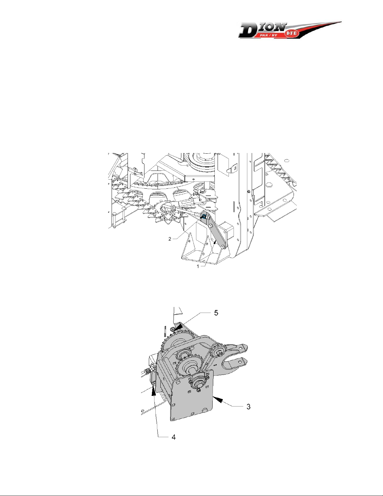
Retirez le support de tendeur (1) et désassembler le ressort (2) de la tige du tendeur en
enlevant les deux écrous.
Étape 3 : Installation du support gauche
Installez le support (3) à l’aide de boulon à bride 1/2’’ x 1-1/4’’ (4) et 1/2’’ x 1’’ (5) avec
écrous à bride ½’’.
Instructions d’installation/ Installation instructions : F6413T936
Ensemble Adaptateur F64 / Adapter Kit F64 : GEHL
22 janvier 2013
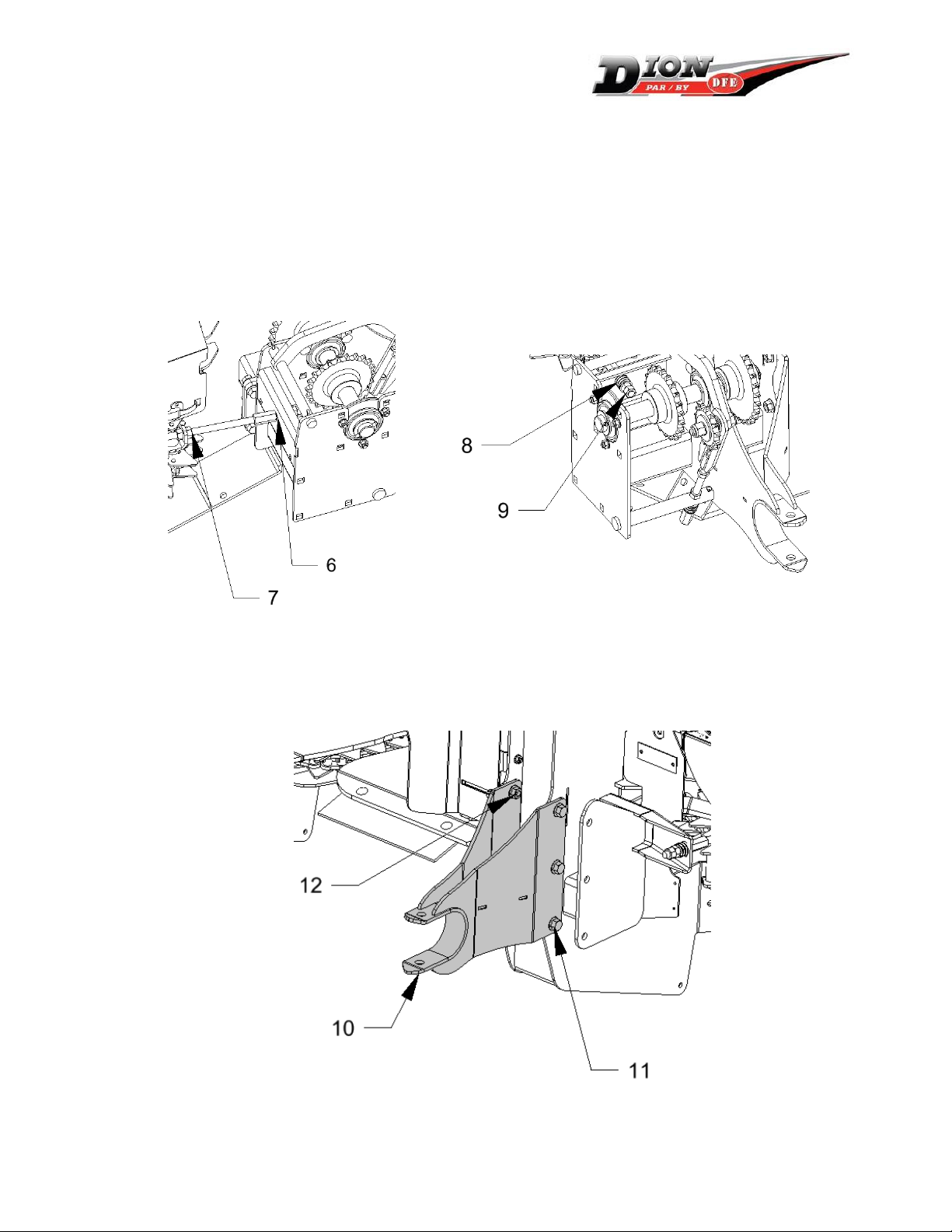
Desserrez le boulon de blocage de la tige du tendeur (7) pour fermer complètement
l’espace entre la tige et le support (6).
Insérez le ressort (8) et serrez-le en place pour qu’il ait une longueur compressée de 19
à 22mm (3/4 à 7/8’’). Bien serrer les écrous d’arrêt l’un sur l’autre (9)
Ajuster la tension du tendeur jusqu’à ce que l’espace entre le boulon et le support (6)
atteigne 1,5mm (1/16’’) maximum. Serrez l’écrou de blocage (7). Voir le manuel
d’opérateur pour l’ajustement de la tension de la chaîne.
Étape 4 : Installation de l’attache droite.
Installez l’attache droite (10) dans les trous indiqués en utilisant des boulons ½’’ x 1’’
(11) et écrous ½’’ (12).

Instructions d’installation/ Installation instructions : F6413T936
Ensemble Adaptateur F64 / Adapter Kit F64 : GEHL
22 janvier 2013
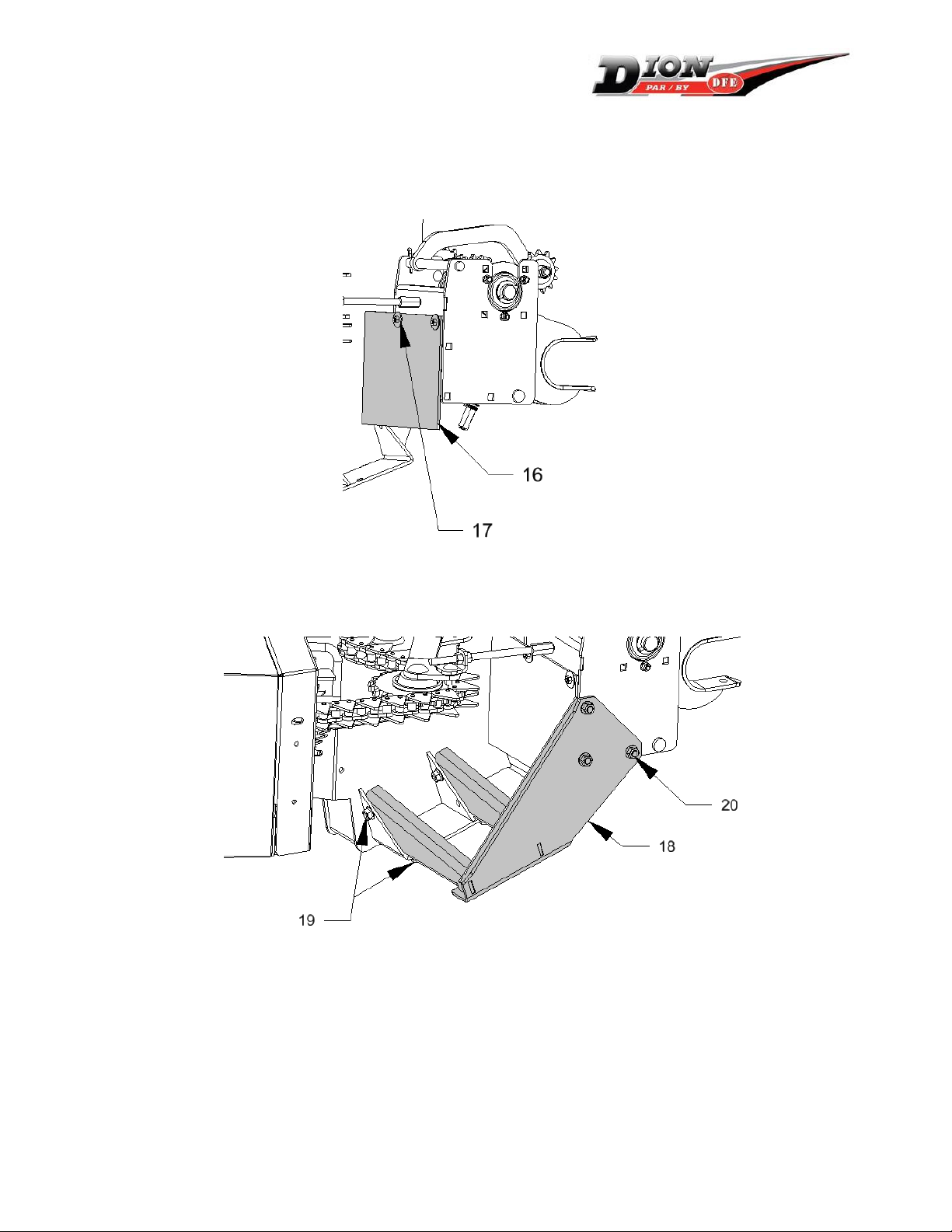
Étape 5 : Installation du caoutchouc de protection
Installer le caoutchouc de protection (16) avec des boulons à voiture 5/16’’ x ¾’’ des
rondelles plates à grand diamètre (17) et des écrous hexagonaux.
Étape 6 : Installation de la rampe gauche
Installez la rampe gauche (18) à l’aide de trois boulons à voiture 1/2" x 1’’ (20) et 4
boulons ½’’ x 1’’ à bride (19), avec écrous à bride ½’’ .
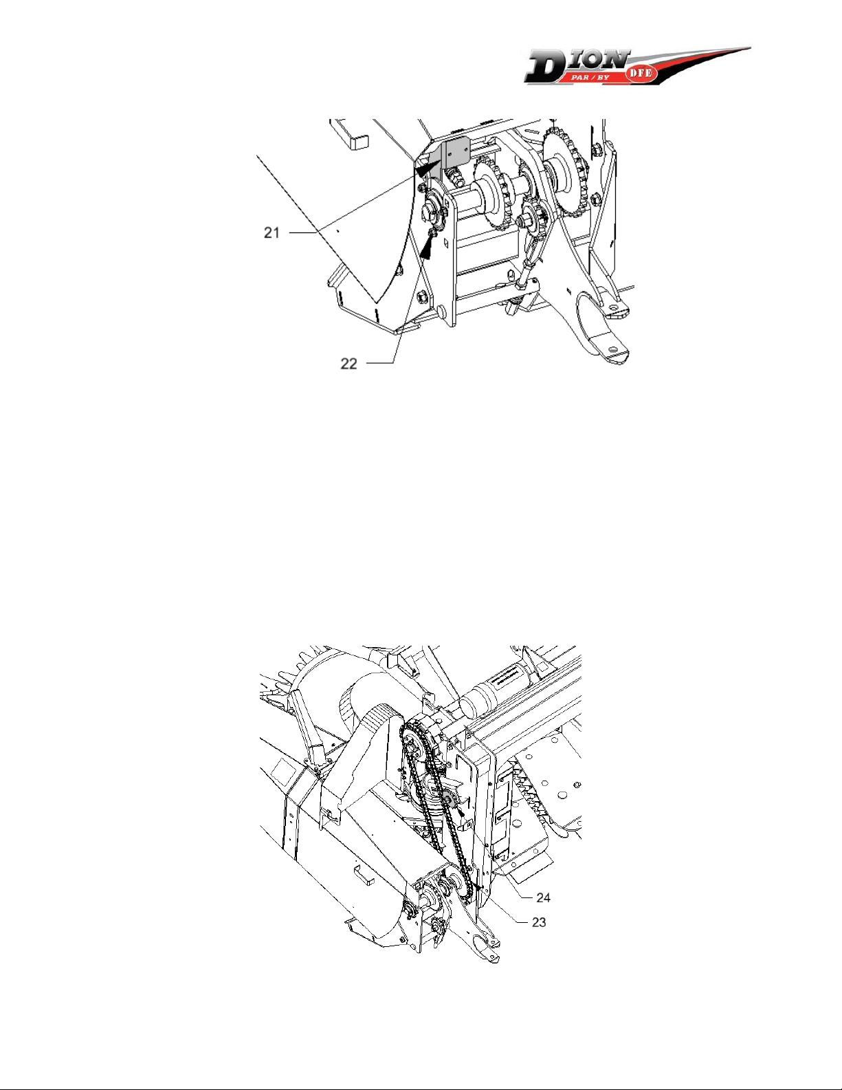
Étape 7 : Installation du support de garde
Desserrez le support de garde (21) en desserrant d’abord les deux boulons
correspondant (22).
Ajustez la position du support pour qu’il s’emboîte dans le garde et que ce dernier
soit aligné avec le châssis sur le dessus.

Instructions d’installation/ Installation instructions : F6413T936
Ensemble Adaptateur F64 / Adapter Kit F64 : GEHL
22 janvier 2013
Installez la barrure avec les vis #10 fournies en s’assurant que le garde reste bien en
place lorsque la barrure est actionnée.
Serrez les boulons du support du garde.
Étape 8 : Installation de la chaîne
Installez la chaîne (23).
Vérifier l’alignement du tendeur (24) et ajuster les espaceurs au besoin.
Tendre la chaîne en appuyant sur la roue a chaîne (24) et le serrer en place. La chaine
devrait avoir un jeu de de 6mm (1/4’’) sur le côté « mou ».

Instructions d’installation/ Installation instructions : F6413T936
Ensemble Adaptateur F64 / Adapter Kit F64 : GEHL
22 janvier 2013
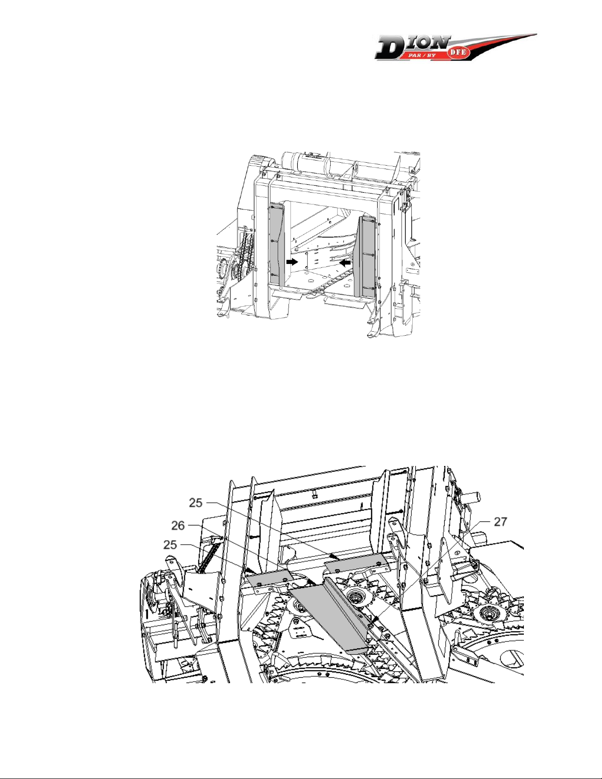
Étape 9 : Installation des gardes d’entrée
Placez les gardes de rouleau tel qu’indiqué.
Ajustez les gardes pour qu’ils s’insèrent entre le rouleau d’alimentation et les côtés de la
fourragère. Serrez bien en place (Peut être fait lorsque installé sur la fourragère).
Étape 10 : Installation optionnelle
Les caoutchoucs (25) servent à réduire la perte de grain et d’épis entre le cueilleur et les
rouleaux d’alimentation de la fourragère.
Le dalot de canal (item 26) doit être installé seulement dans le cas de perte d’épis. Il
permet de réduire les pertes devant les rouleaux d’alimentation entre les caoutchoucs.
Pour l’installer, retirer les boulons des déflecteurs (27), puis installez le dalot. Ne pas
retirer les déflecteurs. En cas de bourrage, retirez le dalot.
Instructions d’installation/ Installation instructions : F6413T936
Ensemble Adaptateur F64 / Adapter Kit F64 : GEHL
22 janvier 2013
Étape 11 : Installation sur la fourragère
Soulevez le nez à maïs par le crochet spécifié et avancez vers la fourragère.
Positionnez le nez sur les points d’attache et placez les goupilles.
Installez la chaîne d’entraînement et ajustez le tendeur.
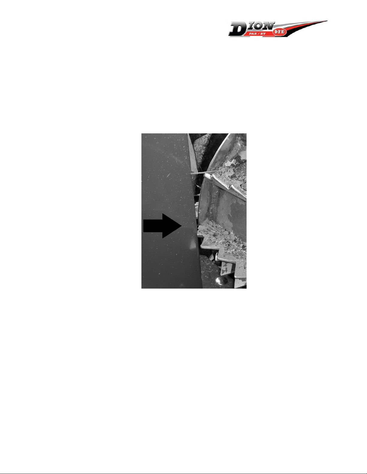
IMPORTANT: AVANT D’OPÉRER LE CUEILLEUR À MAÏS, VÉRIFIEZ QU’IL N’Y A AUCUNE
INTERFÉRENCE ENTRE LE BEC ET LE ROULEAU D’ALIMENTATION DU HAUT DE LA
FOURRAGÈRE LORSQU’IL EST COMPLÈTEMENT RELEVÉ. INSÉREZ AU BESOIN UN
COLLET À CET EFFET POUR RÉDUIRE LE DEPLACEMENT DU CYLINDRE HYDRAULIQUE DE
RELEVAGE POUR PRÉVENIR LES DOMMAGES À LA FOURRAGÈRE OU AU CUEILLEUR.
Ajustez la flottaison de la fourragère pour réduire le poids au sol des pointes avant à
moins de 45kg (100 lbs).
Étape 12 : Opération
Se référer au manuel d’opérateur pour la mise en marche et les ajustements nécessaires
dans les premières heures d’opération.
Suivre un programme d’entretien rigoureux pour assurer une durabilité de la machine.
Instructions d’installation/ Installation instructions : F6413T936
Ensemble Adaptateur F64 / Adapter Kit F64 : GEHL
22 janvier 2013
Installation instructions
Step 1: Reception
See operator’s manual for the reception and removal of transport skid. Important :
Remove the temporary lifting arm before operating the header.
Step 2: Preparation
Open the left side guards as shown.
Remove the tightener bracket (1) and disassemble the spring (2) from the tightener rod
by removing the two locking nuts.
Step 3: Installation of the left support
Install the support (3) with provided flange bolts 1/2’’ x 1-1/4’’ (4) and ½” x 1” (5).

Instructions d’installation/ Installation instructions : F6413T936
Ensemble Adaptateur F64 / Adapter Kit F64 : GEHL
22 janvier 2013
Loosen the tightener rod (7) to close the space between the rod and the support (6).
Insert the spring (8) and compress it to a length of 19 to 22mm (3/4 à 7/8’’). Tighten
well the nuts against each other (9).
Adjust the tension of the tightener until the gap between the nut and the support (6)
reaches a maximum of 1,5mm (1/16’’). Tighten the locking nut (7). See the operator’s
manual to adjust the chain tension.
Step 4: Installation of the right mating hands
Install the right mating hand (10) on the frame as shown using 1/2” x 1” bolts (10)
and flange nuts (12).
Instructions d’installation/ Installation instructions : F6413T936
Ensemble Adaptateur F64 / Adapter Kit F64 : GEHL
22 janvier 2013
Step 5: Installation of rubber guard
Install the rubber flap (16) with carriage bolts 5/16” x ¾” with large flat washer (17)
with regular hexagonal nuts.
Step 6: Installation of the left ramp
Install the left ramp (18) with three carriage bolts ½”x1” (20) and 4 flange bolts ½” x
1” (19), and flange nuts ½”.
Step 7: Installation of guard support
Loosen the support (21) by first loosening the two corresponding bearing flange
bolts.
Adjust the position of the support to obtain a smooth engagement with the guard
and a good alignment with the frame.
Instructions d’installation/ Installation instructions : F6413T936
Ensemble Adaptateur F64 / Adapter Kit F64 : GEHL
22 janvier 2013
Install the lock with #10 screws and nuts provided. Ensure the guard is well in place
when the lock is clamped.
Tighten all the guard support bolts.
Step 8: Installation of the driving chain
Install the chain (23).
Check the alignment of the tightener sprocket (24) and adjust the spacer positions as
required.
Bind the chain by pushing on the sprocket and tighten it. The chain should have a 6mm
(1/4”) slack on the loose side.
Instructions d’installation/ Installation instructions : F6413T936
Ensemble Adaptateur F64 / Adapter Kit F64 : GEHL
22 janvier 2013
Step 9: Installation of the feedroll guards
Position the guards as shown.
Adjust their position to fit between the feedroll and the side guards of the harvester.
Tighten well in place (Can be done when the header is installed on the harvester).
Step 10 : Optional installation
The rubber deflectors (25) on the header are used to reduce the loss of grain or small
particles between the feedroll and header.
The channel (item 26) must be installed only in case of loss of cobs. It reduces the loss
occurring in front of the feedrolls between the rubbers. To install it, remove the
deflector bolts (27), and then install the channel. Do not remove the deflectors. In case
of plugging that may occur in wet or weedy conditions, remove the channel.

Instructions d’installation/ Installation instructions : F6413T936
Ensemble Adaptateur F64 / Adapter Kit F64 : GEHL
22 janvier 2013
Step 11: Installation on the harvester
Lift the rotary corn head as shown in the operator’s manual.
Position the head on the harvester and install the lock pins.
Install the drive chain and adjust the tigthener.
IMPORTANT: BEFORE OPERATING THE HEADER, VERIFY THAT THERE IS NO
INTERFERENCE BETWEEN THE HEAD AND THE HARVESTER TOP FEEDROLL WHEN THE
HEAD IS LIFTED TO ITS HIGHEST POSITION. INSERT A SLEEVE IF NEEDED ON THE LIFT
HYDRAULIC CYLINDER ROD TO REDUCE ITS STROKE AND PREVENT DAMAGE TO THE
HEADER OR THE HARVESTER.
Adjust the flotation on the harvester to reduce the weight at the tip of the header side
dividers to less than 45kg (100 lbs).
Step 12 : Operation
Refer to the operator’s manual for the start-up procedure.
Follow a strict maintenance program to lengthen the life of the header.
Table of contents
Languages:
Other Dion Farm Equipment manuals


Popular Farm Equipment manuals by other brands


Krone
Krone Swadro 807 Original operating instructions

Mauldin
Mauldin 1860 Operation manual

Kerbl
Kerbl EasyHeat 23A Instructions for use

Rotomec
Rotomec HURRICANE H40-048 Operator's manual

Westeel
Westeel Bin on Hopper Pea Installation and Storage Instructions

Carlisle
Carlisle DeVILBISS GFC-501 Service manual

Producer's PRIDE
Producer's PRIDE Ranch Chicken Coop Care Instructions

Farm King
Farm King 1342 Operator and parts manual

Krone
Krone Swadro 35 operating instructions

Woodbay
Woodbay FDS 9200 manual

Farm King
Farm King BW200 Operator and parts manual

AGRITAL
AGRITAL ISEKI TXG Series Installation guide & parts list