Dion F67 User manual

Operator’s Manual
2-Row Rotary Corn Attachment
(1.5m)
Manual no. F6715E968
F67

2
F6715E968
DION-AG INC. LIMITED WARRANTY TERMS AND CONDITIONS
Covered by Warranty – Under the warranty, Dion-Ag guarantees its new machinery and/or equipment to
be free of defects, both in workmanship and material, for a period of one (1) year from the time of delivery by
the dealer. Dion-Ag Inc. will repair or replace, at its discretion and without charge for service parts or labour,
any defective part of the equipment on condition that the machinery and/or equipment has been operated
in accordance with the instructions contained in the Dion-Ag Inc. Operator’s Manual.
Not covered by Warranty – This warranty does not cover: (1) service parts and labour needed to main-
tain the unit; and (2) the replacement of parts due to normal wear and tear. The owner is responsible for
these items. Some examples of maintenance and normal wear parts are: oil, lubricants & other uids, belts,
knives, clutch and clutch discs, roller chain, paddles, etc. Dion-Ag Inc. is not responsible for depreciation or
damage caused by normal wear, lack of reasonable and proper maintenance, failure to follow operating in-
structions, misuse, lack of proper protection during storage, vandalism, the elements, collision or accident.
Securing Warranty Service – To secure warranty service, the purchaser must report the machinery and/
or equipment defect to an authorized dealer and request warranty service within the applicable warranty
terms.
Owner’s Obligation – It is the responsibility of the Owner to transport the equipment to the service shop of
an authorized Dion-Ag Dealer or to reimburse the dealer for any travel or transportation expense involved
in fullling this warranty. This warranty does NOT cover rental of replacement equipment during the repair
period, loss of prots, or other commercial loss, and any or all incidental or consequential damages, over-
time labour charges and/or freight charges for replacement parts.
Limitations of This Warranty – No agent, employee or representative of Dion-Ag Inc. has the authority to
amend, or modify, in any manner whatsoever, the terms of the present warranty. The express warranties
herein contained exclude all other express, implied or statutory warranties. THIS WARRANTY IS IN LIEU
OF ALL OTHER WARRANTIES INCLUDING THE WARRANTIES OF MERCHANTABILITY AND/OR FIT-
NESS FOR ANY PARTICULAR PURPOSE.
Right to Inspect – Dion-Ag and its authorized agents reserve the right to inspect the purchaser’s Dion-Ag
product to determine if a defect in material or workmanship exists prior the commencement of any covered
repairs. It is the purchaser’s responsibility to ensure availability and/or delivery of the product to Dion-Ag
for the purpose of inspection.
Right to Make Design Changes – Dion-ag reserves the right to make changes in the design and other
changes in its products at any time and from time to time without notice and without incurring any obligation
of its part to modify, improve or add to products previously ordered from Dion-Ag and sold or shipped by
Dion-Ag.
Liability – Dion-Ag Inc. shall not be liable, if, during the use of the machinery and/or attachment, the sec-
urity guards have been removed, modied, or have not been properly maintained.
The Warranty shall not apply if the instructions mentioned in this manual have not been followed completely
and correctly. Nor will the warranty apply if the owner or any third party modies the machine without Di-
on-AG’s knowledge and/or authorization. Every purchaser, when buying a Dion-Ag machine, agrees and
undertakes to use and operate the machinery and its component parts safely, and in accordance with all
applicable laws, and in accordance with the Operator’s Manual. Furthermore, the purchaser agrees and
accepts to indemnify and hold harmless Dion-Ag for all losses and damages to any person or property re-
sulting from the purchaser’s non-compliance with the terms and conditions of this warranty. Each purchaser
further agrees to bring the warranty to the attention of any subsequent purchaser, and to obtain agreement
therein as a condition of resale or transfer.
juillet26,201510:13AM
3
F6715E968
F67 Rotary
Corn Attachment
TO OUR CUSTOMER
We appreciate your condence in DION Farm Equipment and thank you for your trust. In prepar-
ing this manual, we hope we have provided you with a valuable tool for operating and maintaining
this ne machine. Use this manual as your guide. Following the instructions given here will result
in many years of dependable service from your machine.
Your Dealer can give you assistance with parts and specially trained personnel to assist you in
repair and maintenance.
Call your Dealer if you need any assistance or information.

4
F6715E968

5
F6715E968
TABLE OF CONTENTS
SPECIFICATIONS.............................................................................................................................................. 6
SERIAL NUMBER LOCATION ........................................................................................................................... 7
CHECK LIST ...................................................................................................................................................... 8
FOREWORD ...................................................................................................................................................... 9
SAFETY RULES................................................................................................................................................. 11
TRANSMISSION SHAFT OPERATION................................................................................................... 13
STOPPING PROCEDURES.................................................................................................................... 13
GUARDS AND SHIELDS ........................................................................................................................ 14
SAFETY SIGN LOCATION................................................................................................................................. 15
SAFETY SIGN APPLICATION PROCEDURE......................................................................................... 16
INSTALLATION .................................................................................................................................................. 17
RECEPTION (BY DE DEALER) .............................................................................................................. 17
INSTALLATION OF THE ROTARY CORN ATTACHMENT ON THE FORAGE HARVESTER .............. 17
OPERATING....................................................................................................................................................... 20
OPERATING TIPS................................................................................................................................... 20
OPERATING SPEED............................................................................................................................... 20
BOLT TORQUE SPECIFICATIONS......................................................................................................... 20
MEASURING GAUGE............................................................................................................................. 20
LUBRICATION.................................................................................................................................................... 22
LUBRICATION CHART............................................................................................................................ 22
CHAIN LUBRICATION............................................................................................................................. 22
TIGHTENER ROD LUBRICATION .......................................................................................................... 23
GEAR BOXES OIL LEVEL ...................................................................................................................... 23
TIGHTENER GREASING........................................................................................................................ 23
OVERRUNNING CLUTCH GREASING .................................................................................................. 23
DRUM GREASING.................................................................................................................................. 24
ADJUSTMENTS - MAINTENANCE.................................................................................................................... 25
GROUND CLEARANCE ADJUSTMENT................................................................................................. 25
CONVEYOR CHAIN TENSION ADJUSTMENT ...................................................................................... 25
CONVEYOR CHAIN VERIFICATION ...................................................................................................... 26
CHAIN SYNCHRONIZATION .................................................................................................................. 28
CHAIN REPLACEMENT.......................................................................................................................... 29
INTERMEDIATE CHAIN TENSION ADJUSTMENT ............................................................................... 29
DISK CLEANER ADJUSTMENT ............................................................................................................. 30
KNIFE SECTION REPLACEMENT ........................................................................................................ 30
DEFLECTOR-KNIFE REPLACEMENT ................................................................................................... 31
STRAIGHTENING UP THE DRUM FINGERS ........................................................................................ 31
CUTTING DISK BELT TENSION ADJUSTMENT.................................................................................... 31
DEFLECTOR ADJUSTMENT .................................................................................................................. 32
FRICTION DISKS REPLACEMENT........................................................................................................ 32
DRIVE BELT REPLACEMENT ................................................................................................................ 33
DRUM ADJUSTMENT ............................................................................................................................. 33
SCRAPER ADJUSTMENT ...................................................................................................................... 34
MAINTENANCE SUMMARY.............................................................................................................................. 35
STORAGE .......................................................................................................................................................... 36
TROUBLESHOOTING ....................................................................................................................................... 37

6
F6715E968
Specications and design are subject to change without notice
and without liability therefore
NOTE: Specications apply only to the F67 model.
Shipping
Dimensions F67 F67
Dion
F67
John DeereTM
F67 NewHollandTM /
CaseIHTM
Overall
Length 189 cm (74.5”) 205 cm (80.5”) 205 cm (80.5”) 203 cm (80”)
Overall
Width 200 cm (79”) 200 cm (79”) 200 cm (79”) 200 cm (79”)
Overall
Height 122 cm (48”) 122 cm (48”) 122 cm (48”) 122 cm (48”)
Weight
500 kg (1100 lbs) 540 kg (1188 lbs) 525 kg (1155 lbs) 530 kg (1166 lbs)
SPECIFICATIONS
7
F6715E968
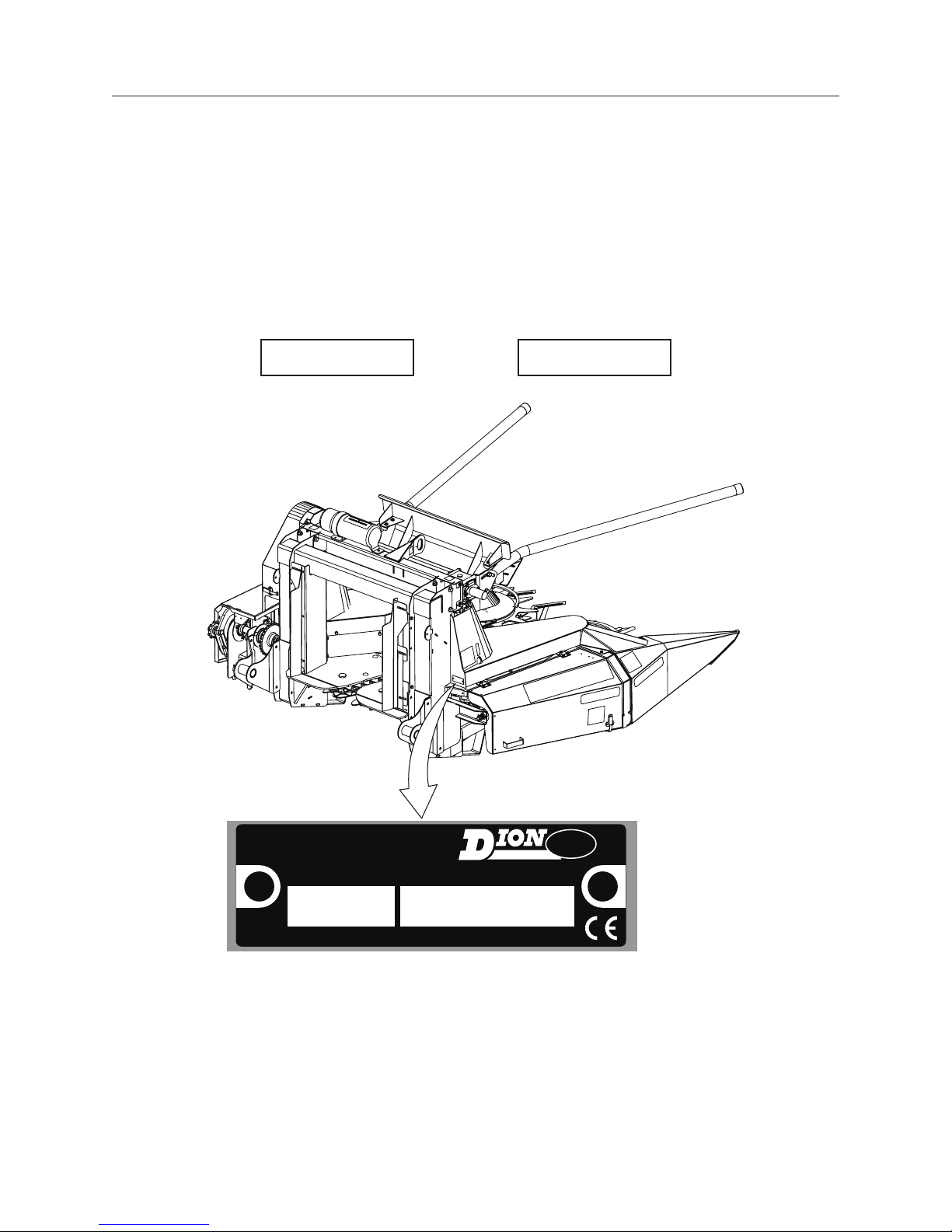
For your convenience, write down in full in this manual both the model and serial numbers of your
machine, as shown on the name plate illustrated below. Always mention both the model and
the serial numbers when ordering parts or regarding any other correspondence referring to your
machine
Write down your number here:
MODEL NO. SERIAL NUMBER
SERIAL NUMBER LOCATION
R.H.
DROIT
REAR
ARRIÈRE
L.H.
GAUCHE
FRONT
DEVANT
DFE
MADE IN CANADA
D.F. E. INC.
BOISBRIAND QUE.
MODEL NO.
SERIAL NO.
PAR / BY

8
F6715E968
PRE-SEASON CHECKS
Check condition of guards and knives
Check condition of chains and chain guides
Check chain tension and elongation
Check condition and tension of drive belts
Look for loose or missing bolts and parts
Make sure no safety decal is missing and make sure they are readable
Check condition of saw teeth
Check condition of drum ngers. Make sure they are solid and straight
Check oil levels on gear boxes
DAILY
Check tension of belts and chains
Clean machine
Lubricate following instructions found in maintenance section
Make sure all guards are in good condition
CHECK LIST

9
F6715E968
TO OUR CUSTOMER
The following pages and illustrations are printed to
help supply you with the knowledge to better oper-
ate and service your F67 Rotary Corn Attachment.
Any piece of equipment needs, and must have a
certain amount of service and maintenance to keep
it in top running condition. We have attempted to
cover all the adjustments required to t most con-
ditions; however, there may be times when special
care must be taken to t a condition.
Study this operator’s manual carefully and become
acquainted with all the adjustments and operating
procedures before attempting to operate your new
equipment. Remember, it is a machine and it has
been designed and tested to do an efcient job in
most operating conditions and will perform in rela-
tion to the service it receives.
If special attention is required for some conditions,
ask your Dion Dealer; his parts and Service Organi-
zation will be glad to help and answer any questions
on operation and service of your new machine.
THIS MANUAL SHOULD REMAIN WITH THE
MACHINE WHEN SOLD
This manual was prepared from the latest product
information available at publication time. The Com-
pany reserves the right to make changes at any time
without notice.
The safety section of your Operator’s manual is in-
tended to point out some of the basic safety situ-
ations which may be encountered during the nor-
mal operation and maintenance of your F67 Rotary
Corn Attachment, and to suggest possible ways of
dealing with these situations. This section is NOT
a replacement for other safety practices featured in
other sections of this book.
WARRANTY INFORMATION
Your Dion Warranty for this machine appears on
your copy of the Retail Purchase Order and War-
ranty Terms and Conditions Statement which you
received from your dealer when you purchased the
F67 Rotary Corn Attachment.
As indicated on the Retail Purchase Order signed by
you and your dealer, you, the equipment purchaser,
shall assume charges for service calls or transporta-
tion of equipment to and from the location of servic-
ing Dion dealer.
SAFETY
The safety of the operator is one of the main con-
cerns in designing and developing a new F67 Ro-
tary Corn Attachment. Designers built in as many
safety features as possible. However, every year
accidents occur which could have been avoided by
taking a more careful approach to handling farm ma-
chinery and implements.
Read and implement the safety instructions detailed
in the safety section of this manual.
FOREWORD

10
F6715E968
SAFETY ALERT SYMBOL
The symbol above calls your attention to instructions
concerning your personal safety. It is found throughout
the manual as well as on the machine to point out spe-
cic hazards and ways to avoid them. Always follow the
instructions to minimize the risk of personal injury or
death.
DANGER, WARNING AND CAUTION
Whenever you see the words and symbols shown be-
low, used in this manual and on decals, you MUST
take note of their instructions as they relate to personal
safety.
DANGER: Indicates an imminently
hazardous situation that, if not avoided, will
result in DEATH OR VERY SERIOUS INJURY.
WARNING: Indicates a potentially
hazardous situation that, if not avoided,
could result in DEATH OR SERIOUS
INJURY.
CAUTION: Indicates a potentially
hazardous situation that, if not avoided,
may result in MINOR INJURY.
IMPORTANT: The word IMPORTANT is used to identi-
fy special instructions or procedure which, if not strictly
observed, could result in damage to, or destruction of
the machine, process or its surroundings.
NOTE: The word NOTE is used to indicate points
of particular interest for more efcient and
convenient repair or operation.
SIGNS
WARNING: DO NOT remove or obscure
Danger, Warning, Caution safety signs or
Instruction signs that are not readable or are
missing. Replacement signs are available
from your Dealer in the event of loss or
damage. The actual location of these Safety
signs is illustrated on pages 15 and 16.
FOLLOW A SAFETY PROGRAM
For proper operation of a corn attachment, you must
be a qualied and authorized operator. To be qualied,
you must read and understand the written instructions
supplied in this Operator’s Manual, have training, and
know the safety rules and regulations for the job.
Some local regulations specify that no one under the
age of 16 years, for example, may operate power ma-
chinery. This includes tractors. It is your responsibility
to know what these regulations are, and obey them, in
the operating area or situation. These will include, but
are not limited to, the following instructions for proper
operation.
WARNING: An operator should not use alco-
hol or drugs which can change their alertness
or coordination. An operator on prescription
or “over the counter” drugs needs medical
advice on whether or not he or she can prop-
erly operate machines.
A WORD TO THE OPERATOR
It is YOUR responsibility to read and understand the
safety section in this manual before operating your
tractor. You must follow these safety instructions that
take you step by step through your working day.
In reading this section, you will note that illustrations
have been used to highlight certain situations. Each
illustration is numbered and the same number appears
in the text in parenthesis. This number is placed at the
end of the written text that refers to the illustration.
Remember that YOU are the key to safety. Good safe-
ty practices not only protect you, but also the people
around you. Study the features in this manual and
make them a working part of your safety program.
Keep in mind that this safety section is written only for
this type of machine. Practice all other usual and cus-
tomary safe working precautions, and above all.
REMEMBER - SAFETY IS YOUR RESPONSIBILITY.
YOU CAN PREVENT SERIOUS INJURY OR DEATH.
WARNING: In some of the illustrations used
in this Operator Instruction Book, panels or
guards may have been removed for clarity.
Never operate the machine without these
components in position. If the removal of
panels or guards is necessary to make a re-
pair, they MUST be replaced before opera-
tion.
SAFETY RULES

11
F6715E968
• Disengage the PTO and shut off engine before
leaving the operator’s seat for refueling, lubricat-
ing or adjusting the machine.
• The tractor engine ignition key must be
removed each time the operator leaves the tractor.
• Wear appropriate clothing, safety boots or shoes.
Do not operate the machine when visibility is bad,
or during night, in poor lighting.
• When driving on a public road, or on hilly land you
must remove the electrical box ignition key and
put the locking pin in the stop pawl of the quick-
disconnect hitch to prevent unlocking. This lock-
ing pin should also be used for the manual quick-
disconnect hitch.
• Attach a safety chain of at least 20,000 lbs (9071
Kg) capacity for transportation.
• Keep children away from the machine at all times.
Maximum traveling speed of a forage harvester
should not exceed 20 mph (34 km/h).
• Carefully read all safety signs applied on the ma-
chine. If they are damaged, replace them imme-
diately.
• If a feeding or throwing mechanism should be-
come jammed, never attempt to unblock it or re-
move any material when the machine is in motion
or the tractor engine running.
• Never manually feed the rotary corn attachment.
• Never remove guards or make adjustments while
the machine or tractor engine is running.
• Never attempt to check or adjust chains while the
machine is running.
• Keep hands and feet away from the pick-up
chains and the saw.
• Make sure all rotating parts are stopped and the
tractor engine is turned off before cleaning the
machine throat.
• Never park the attachment in the transportation
position. Lower the attachment to the ground rst.
• Before starting the tractor engine, make sure all
guards, shields, and doors are in place and prop-
erly secured and check the machine thoroughly for
possible loose parts or bolts and tighten them.
• Always pick-up tools after performing any adjust-
ment.
• Never allow riders on any part of a machine.
• Block elevated components before servicing
equipment.
• Never lubricate or clean any part while the ma-
chine or tractor engine is running.
• Keep hands and body out of hitch area when at-
taching towing vehicle.
WARNING: Hydraulic uid under pressure
can penetrate the skin or eyes and cause
serious personal injury, blindness or death.
Fluid leaks, under pressure, may not be vis-
ible. Use a piece of cardboard or wood to
nd leaks. DO NOT use your bare hand.
Wear safety goggles for eye protection. If
any uid is injected into the skin, it MUST be
surgically removed within a few hours by a
doctor familiar with this type of injury.
• Securely block the wheels from moving before
working on or under the machine.
• Use a lift system with a minimum capacity of 1500
lbs (680 kg) to install the attachment on a forage
harvester.
• Never pull a full box behind a forage harvester
when driving on a public road.
• Make sure to meet local regulations regarding
wide loads on public roads.
SAFETY RULES

12
F6715E968
SAFETY RULES
TRANSMISSION SHAFT OPERATION
• POWER-TAKE-OFF DRIVE - Before starting the
tractor engine make sure that the PTO locking de-
vice is properly engaged onto both the tractor and
equipment PTO shafts.
• Never wear loose clothing and keep people, es-
pecially children away from the PTO.
• Do not hook a 1000 RPM tractor on a machine
equipped with a 540 RPM drive and/or a 540 RPM
tractor on a machine equipped with a 1000 RPM
drive.
• Never proceed to the starting of the machine be-
fore making sure all PTO, machine and tractor,
shields are well installed in place.
• The PTO shields should turn freely, be well con-
nected and kept in good condition.
• Never step across any driveline.
• Never use the driveline as a step.
• Keep at least your height away from a rotating
driveline
STOPPING PROCEDURES
No matter what type of machine is being used, it is
extremely hazardous to perform any kind of main-
tenance work while the machine is running. Before
cleaning, adjusting, or greasing, the following pro-
cedures should be followed to stop the attachment:
1. Lower the attachment to the ground.
2. Set the transmission to neutral.
3. Disengage the tractor power-take-off (P.T.O.).
4. Stop the tractor engine.
5. Engage the tractor parking brake.
6. Wait until all rotating parts are totally stopped.
7. Remove the P.T.O. from tractor output shaft.
8. Block all equipment wheels.
DANGER: Rotating driveline contact may
cause serious injury or death.

13
F6715E968
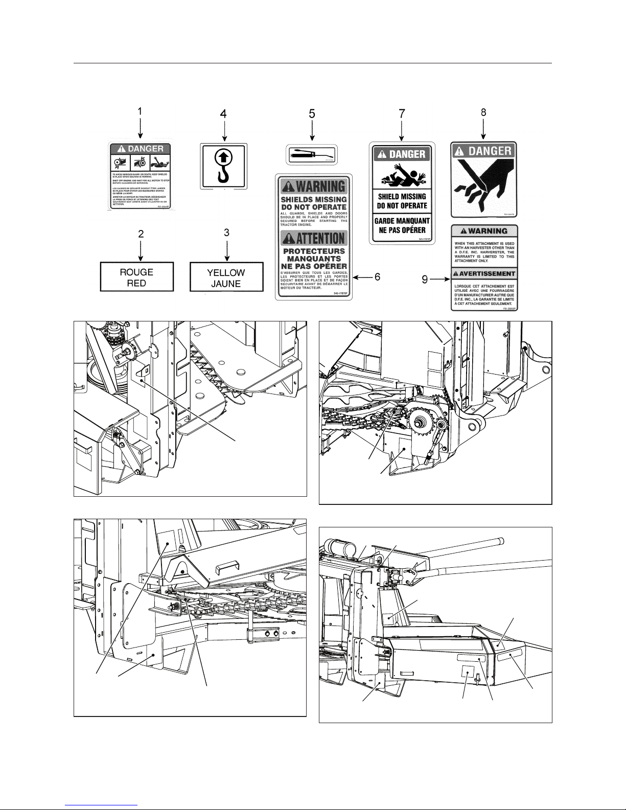
GUARDS AND SHIELDS - FIGURES 1 TO 3
The rotary corn attachment is equipped with guards
and shields wherever an accident is likely to take
place. These guards and shields do not affect the
machine performance. Several safety decals are af-
xed on the machine to remind of potential dangers
Bolted guards cover the driving belts (items 1 in g-
ure 1).
Figure 1 Drive belt guards (item 1) and conveyor chain
guard (item 2)
Hinged guards cover the conveyor chain (items 2 in
gures 1 and 2).
Figure 2 Conveyor chain right guard
An hinged guard covers the intermediate chain
(item 3 in gure 3).
An hinged guard covers the drive shaft (item 4 in
gure 3).
3
4
Figure 3 Intermediate chain guard (item 4) and drive
shaft guard (item 3)
CAUTION: All guards and shields factory
installed should be in place and maintained
in good condition.
SAFETY RULES
14
F6715E968
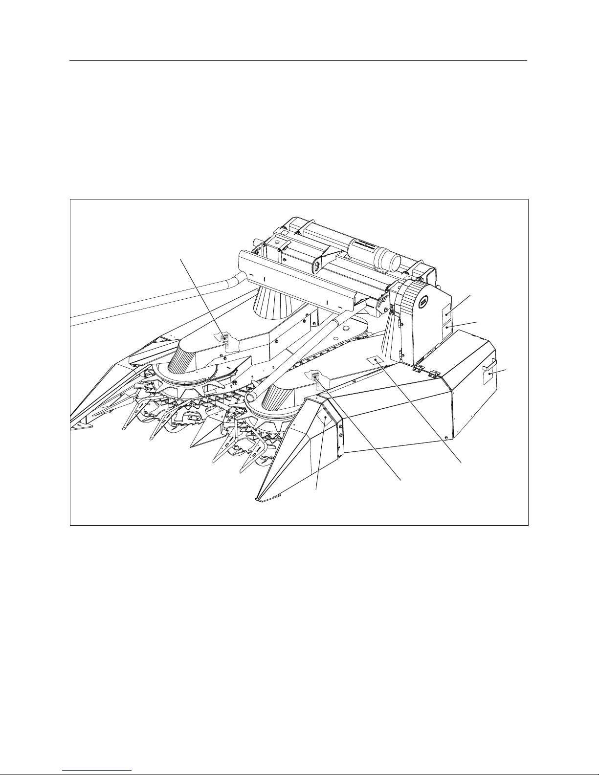
SAFETY SIGN LOCATION
IMPORTANT: All safety decals should be in place and maintained in good condition. Decals should be
readable at all times.
6
Figure 4 Safety sign location
6
1
5
Figure 5 Safety sign locations
6
5
Figure 6 Safety sign locations
47
61
8
3
2
1
Figure 7 Safety sign locations (R.H. side)
15
F6715E968
SAFETY SIGN LOCATION
SAFETY SIGN APPLICATION PROCEDURE
1. The surface should be free from dirt, grease,
earth, or any other foreign material.
2. When the surface is dry, remove a portion of the
backing paper and apply the decal in part and
align its position as per the surrounding parts.
Slowly peel off the remaining backing paper and
apply hand pressure.
3. Press slightly on the surface of the safety sign to
remove all air bubbles.
Figure 8 Safety sign location (L.H. side)
6
6
1
8
1
1
9

16
F6715E968
INSTALLATION
RECEPTION (BY DE DEALER)
The F67 Rotary Corn Attachment is delivered to the
dealer on a shipping skid (item 1) normally accom-
panied by a box (item 2) containing the adaptor kit
for the client’s harvester model. Long forks (2.25 m
or 8’) must be used to lift the skid from the short
side. A note is present on the skid. Standard 1.2 m
(4’) forks are sufcient to lift from the long side. The
lift must have a capacity of 1,8 t (4000 lbs) to lift the
skid from the short side.
1. Place the skid on a at and level surface.
2. Remove the box containing the adaptor kit (item
2). The Attachment is delivered with a temporary
lifting arm for the removal of the skid (item 3).
IMPORTANT: The lifting arm (item 3) should not be
used for moving or lifting the attachment. It should
only be used for laying it at on the ground.
3. Before removing the skid, inspect bolts (item
4) on disks, ngers, knife deectors and drum
bearings.
4. Pass a chain (item 5) with a minimum capacity
of 1500 lbs (680 kg), in the arm hook and make
a closed and safe loop in the chain.
5. Follow standard safety rules for the operation of
forklift, chain-block and chains to proceed.
6. With the lift of chain-block, slowly lift and pull on
the chain to pivot the head to the ground.
7. Remove the chain (item 4).
8. Remove the bolts holding the Attachment and
the skid together.
Figure 9 The 2-Row Rotary Corn Attachment in shipping position
1
4
4
4
4
2
3

17
F6715E968
INSTALLATION
9. The lift arm can now be removed and the At-
tachment may be lifted using the hook on top of
the frame.
10. Refer to the installation instructions of the adap-
tor provided in the box.
The installation is done by the dealer before deliv-
ery to the client. Contact your Dion representative if
needed.
Figure 10 The 2-Row Rotary Corn Attachment in shipping position
Long forks only (8’) - fourches longues seul. (8’)
5
18
F6715E968
INSTALLATION
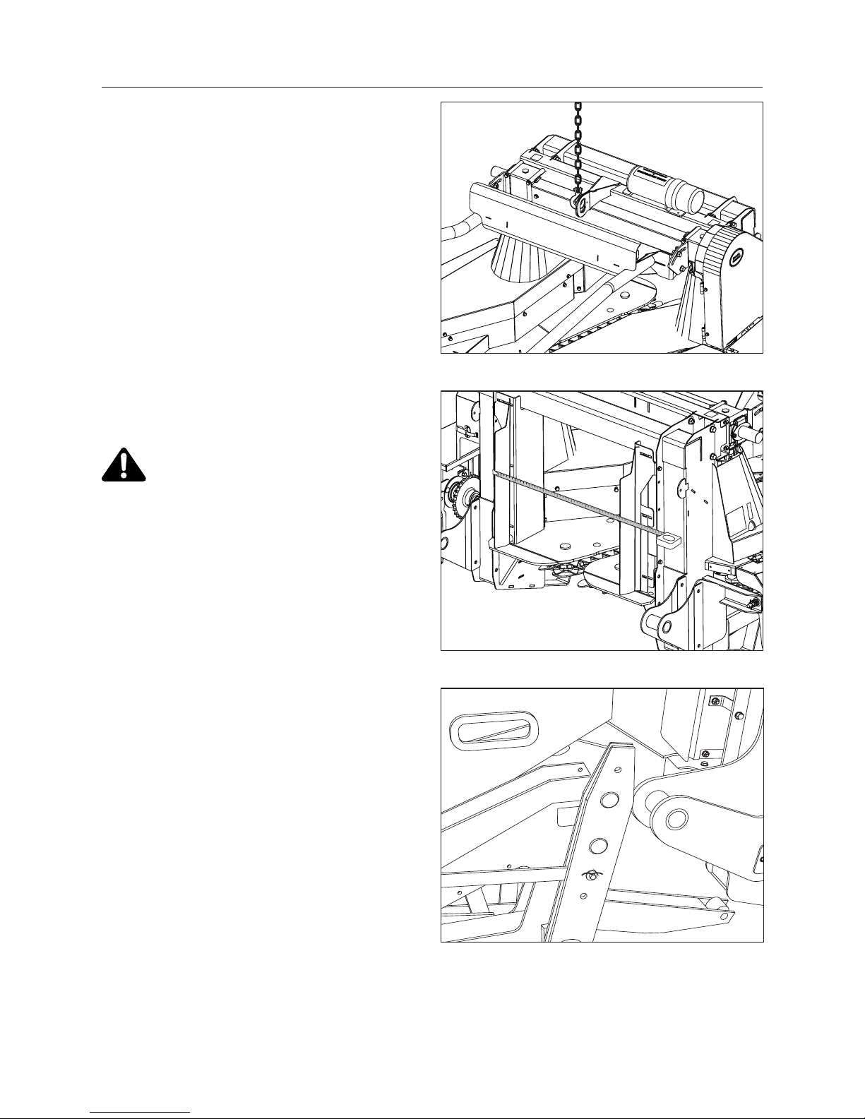
INSTALLATION OF THE ROTARY CORN
ATTACHMENT ON THE DION FORAGE HARVESTER
NOTE: Refer to the Forage Harvester operator’s
manual for brands other than Dion.
NOTE: Always remove tension on balancing springs
before installing or removing attachment from
Forage Harvester.
Make sure the Forage Harvester and the rotary corn
attachment are standing on a at terrain.
The rotary corn attachment is equipped with a sup-
port (gure 11) to lift attachment up for proper instal-
lation. The minimum lifting load must be 1500 lbs
(680 kg).
1. Attach a chain to the lift support (gure 11).
2. Measure the corn attachment opening (gure
12) and adjust if necessary.
IMPORTANT: If the throat sides on the attach-
ment are bent or damaged, it is necessary to
repair them so they will not come in contact
with the feed rolls
3. Slowly move the Forage Harvester toward the
attachment (gure 13), making sure it is well
centered with respect to the connecting pins.
4. Align and adjust the attachment throat sides be-
tween the Forage Harvester sides and the feed
rolls (gure 14).
5. When the attachment is set in place on the For-
age Harvester, put the square lock pins and the
safety pins back in place (gures 15 and 16). It
will be necessary to install two oating springs
and to move the bracket in the middle lifting
hole.
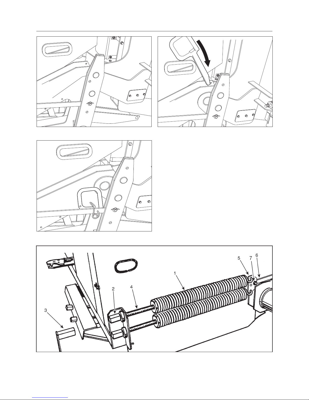
6. Adjust both balancing springs (gure 17). The
purpose of the balancing springs is to counter-
balance the weight of the attachment either to
slightly touch the ground or ease the attachment
hydraulic lifting to avoid possible obstacles in
the eld.
The tension of these springs must be adjusted to
obtain approximately 80-100 lbs (36-45 Kg) at the
end of the ngers.
Figure 11 Lift support
Figure 12 Adjustment
Figure 13 Move attachment toward Harvester
19
F6715E968
Figure 14 Align
Figure 15 Insert square lock pins
Figure 16 Square lock pin in place
7. Adjust the springs (item 1) by turning the screw
(item 2) sleeves (item 4) with the handle (item
3). Two balancing springs are required to op-
erate your attachment. Bolt the spring bracket
(item 5) on the attaching bar (item 6) as shown.
Tighten bolt (item 7) well then install both bal-
ancing springs.
8. Adjust the cylinder stroke to prevent the attach-
ment from touching the feed rolls.
INSTALLATION
Figure 17 Balancing springs set-up when using a Rotary Corn attachment

20
F6715E968
INSTALLATION
9. Install the rotary corn attachment drive chain
(item 1, gure 18). Use the #60 X 36 3/4” lg (93
cm) chain with a #60 connecting link (item 1)
or a #80 X 37” chain, depending on the Forage
Harvester conguration.
Figure 18 Installing the drive chain
NOTE: The #80 sprocket is standard on the attach-
ment. As for the #60 sprocket, it must be
specied when machine is ordered (item 5,
gure 19).
10. Adjust the Forage Harvester lifting arms in op-
erating position. Bring the chain underneath the
tightening sprocket (item 2, gure 18) as shown.
Align the drive chain. Adjust the chain to a nor-
mal tension, loosen nut (item 4, gure 19), tight-
en tightener nut (item 3, gure 19) then tighten
nut (item 4, gure 19).
NOTE: On Forage Harvester models prior to 2006,
it will be necessary to cut out a notch in the
Forage Harvester transmission guard (g-
ure 20) or to order a new guard
NOTE: On NH and CASE IH Forage Harvesters,
install the PTO to start the machine.
5
3
4
Figure 19 Drive chain tension
7 1/4
2
5 1/4
Figure 20 Transmission guard modication
Table of contents
Other Dion Farm Equipment manuals


Popular Farm Equipment manuals by other brands


BSL
BSL Strautmann Sherpa 1201 Translation of the original operating instructions

Landoll
Landoll 5210 Operator's manual

Ferrari
Ferrari MULTIPLA DISC VERSION Operating and service manual

Maschio
Maschio ATTILA 250 Use and maintenance

Moocall
Moocall MoocallHEAT user guide

Landoll
Landoll 1230 Series Operator's manual


