© 2006 Directed Electronics, All rights reserved. N1100X/F-FM 11-06
1
PROGRAMMING INSTRUCTIONS
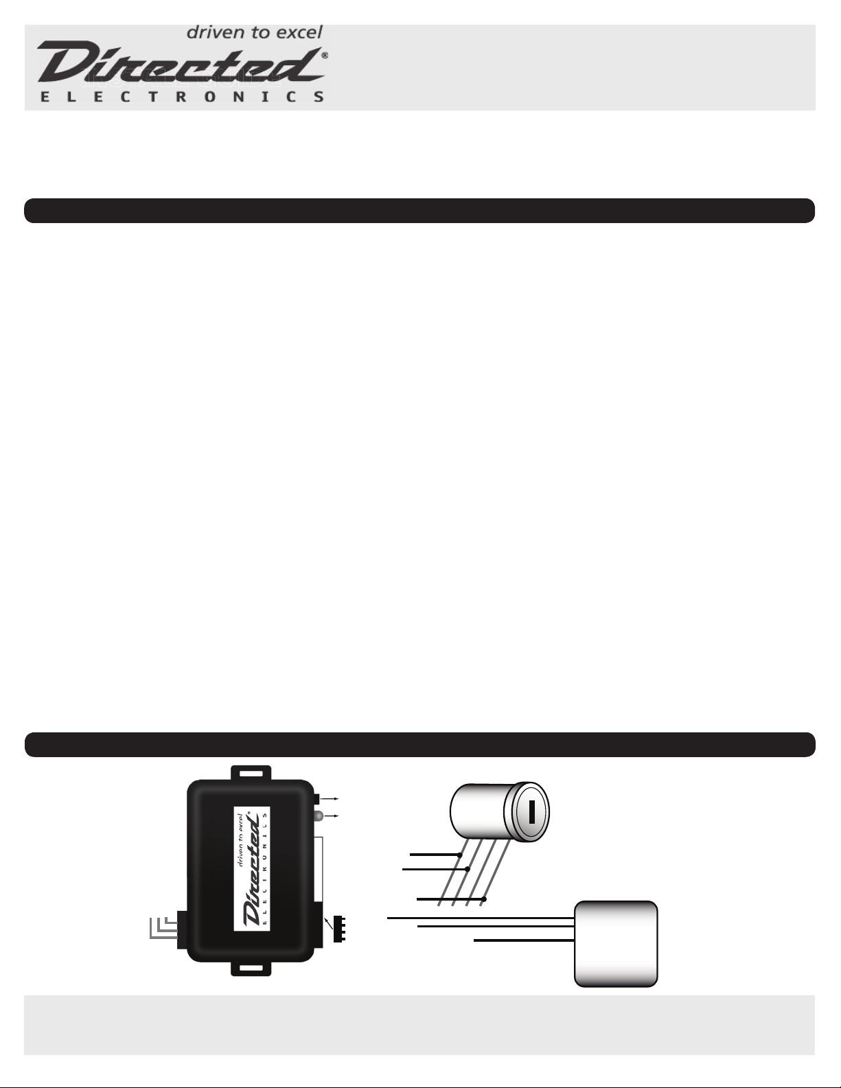
WIRING DIAGRAM
NOTICE: The manufacturer will accept no responsibility for any electrical damage resulting from improper installation of this product, be that either damage to the
vehicle itself or to the installed device. This device must be installed by a certified technician. This guide has been written for properly trained technicians; a certain level
of skill and knowledge is therefore assumed. Please review the Installation Guide carefully before beginning any work.
PRODUCT DESCRIPTION
The 1100X/F-FM interface module is used when installing remote start products in
Ford/Mazda vehicles equipped with a factory immobilizer.The 1100X/F-FM allows
for easy interfacing between the remote start and the factory immobilizer, while
maintaining the integrity of the OEM system.The factory transponder-based anti-
theft system uses a small electronic chip hidden in the key to send a code to the
vehicle’s transceiver when the ignition is energized.The key must be placed in the
ignition and turned to the RUN position.This energizes a coil surrounding the key,
which in turn energizes the chip, which sends a code to the vehicle. If the vehicle
does not detect the code being sent, the vehicle will start and then immediately
shut off or will just crank, and the anti-theft light will flash. The 1100X/F-FM pro-
vides a valid code to the vehicle whenever it is remote started, but does not affect
the immobilizer system during normal vehicle operation; the immobilizer system
remains fully functional.
STEP 1: SELECT INSTALLATION MODE
Complete the wire connections to the vehicle and to the remote starter/alarm
system. Connect all harnesses including the 4-pin power harness.The module
LED will now flash green intermittently. (Note: if this condition is not present, your
module may need to be reset to the factory default).
1. Press and release the programming switch to select installation
mode.
Press the switch to alternate between the two modes (only standard
mode should be used).
1 flash, pause, I flash, pause = (This mode is not used)
2 flashes, pause, 2 flashes, pause = Standard installation mode
2. Once your installation mode is selected, press and hold the
programming button until the LED displays a solid green light for two
seconds.Your installation mode is now programmed. Please proceed
to step 2.
NOTE: Should you wish to change the installation mode, follow the
“Factory Reset” instructions.
STEP 2: DETERMINE TRANSPONDER TYPE
Refer to the transponder cross reference chart to determine transponder type and
programming procedure.
1. If the transponder type is 1, proceed to 2A.
2. If the transponder type is either 2 or 3, proceed to 2B
2A:TransponderType 1
1. Insert the vehicle key into the ignition.
2. Turn ignition to the “ON” position and wait for the LED to illuminate green for
two seconds.
3. Programming is complete.
2B:TransponderType 2 orType 3
IMPORTANT: Both keys are required to complete the programming procedure.
A maximum 5 second delay between each step is permitted. If the delay is
exceeded, the vehicle will not allow programming to continue.The programming
procedure must be restarted.
1. Insert the 1st key into the ignition.Turn ignition to the “ON” position, the LED
will illuminate green. Wait for the car security light to turn off, turn ignition to
the “OFF” position and remove the key.
2. Insert the 2nd key into the ignition.Turn ignition to the “ON” position and
wait for the car security light to turn off.Turn ignition to the OFF” position and
remove the key.
3. Press and release the programming button once and start the vehicle through
use of the remote controlled starter OR “jump” ignition. Wait for LED to illumi-
nate green for two seconds. Programming is complete.
LED DIAGNOSTICS
1. During STEP 2, if the LED flashes red this indicates the wire connections are incorrect.
2. Once programming has been completed, if the LED flashes red the module
failed to learn correctly. Reset module and repeat the programming procedure.
3. When the remote starter is engaged, the led will flash green to indicate the
current transponder mode as follows:
1 x green flash = PATS 1 2 x green flashes = PATS 2 3 x green flashes = PATS 3
If the LED remains illuminated red, the device is incorrectly programmed.
FACTORY RESET
1. Unplug all connectors from the module.
2. Press and hold the programming button while inserting the 4-PIN
standard connector.
3. The LED will begin to flash red. Immediately release the programming button.
The LED will turn on solid for 2 seconds to confirm module reset.
4. Plug remaining connectors and return to: STEP 1: SELECT INSTALLATION
MODE.
BLUE/RED (NC)
BLUE/YELLOW (NC)
GREEN/RED - ECM-RX
GREEN/YELLOW (NC)
GRAY/RED - ECM-TX
GRAY/YELLOW (NC)
ORANGE (NC)
PINK/BLACK (NC)
PINK - IGNITION INPUT
KEY
WHITE
WHITE/RED NC)
WHITE (NC)
RED - 12V
BLACK - GROUND
NO WIRE (NC)
BLUE/WHITE - STATUS OUTPUT REMOTE
STARTER
Programming Button
LED
FORD/MAZDA
TYPE 1 & 2 INSTALLS
Transponder Bypass
WARNING! READ MANUAL PRIORTO INSTALLATION
NOTE TO THE INSTALLER:
THIS GUIDE IS INTENDED FOR USE WITH AN 1100F OR 1100XTHAT HAS BEEN UPDATEDTO AN 1100FM USING THE DIRECTLINK UPDATERTOOL.
DIRECTLINK UPDATER SOFTWARE IS AVAILABLE AT WWW.DIRECTECHS.COM.
1100X/F-FM


