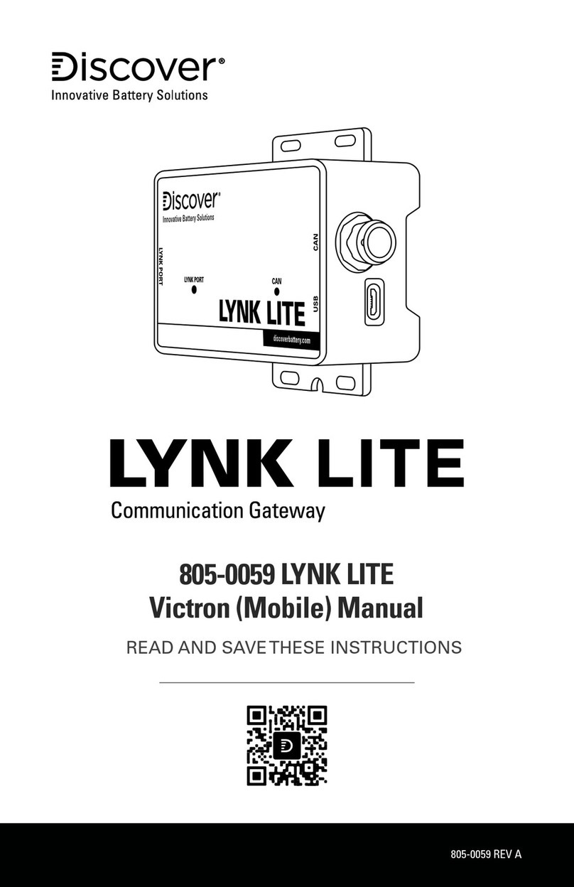
DISCOVER Lynk Lite User manual

1805-0035 REV A
(950-0040)
INSTALLATION AND
OPERATION MANUAL

2
1.0. AUDIENCE, SAFETY, MESSAGES AND WARNINGS 3
1.1 Audience 3
1.2 Safety, Messages and Warnings 3
2.0 About LYNK LITE 4
2.1 Overview 4
2.2 Compatible Batteries and Devices 4
2.3 Compatible Communication Protocols 4
2.4 Firmware Revision 4
3.0 Items Shipped in the Box 4
4.0 Design and Features 5
4.1 Reset Operation 6
4.2 LED Indicators 6
4.3 LYNK Port Pin Assignment 7
4.4 CAN Out Port Pin Assignment 7
4.5 Power Sources for LYNK LITE 8
5.0 Installation 8
5.1 Mounting LYNK LITE 8
5.2 Installing the External Power Source 8
5.3 LYNK Network Communication Cables 9
5.4 Verification of the LYNK Network 11
6.0 Connecting to LYNK ACCESS 11
7.0 Configuring the CAN Communication with LYNK ACCESS 12
8.0 Updating LYNK LITE Firmware with LYNK ACCESS 13
9.0 Specifications 13

3
1.0. AUDIENCE, SAFETY, MESSAGES AND WARNINGS
1.1 Audience
Qualied personnel should perform conguration, installations, service, and
operating tasks in consultation with local utilities and authorized dealers.
Qualied personnel should have training, knowledge, and experience in:
• Installing electrical equipment
• Applying applicable installation codes
• Analyzing and reducing hazards involved in performing electrical work
• Installing and conguring batteries
1.2 Safety, Messages and Warnings
WARNING
Important information regarding hazardous conditions that may result in personal
injury or death.
CAUTION
Important information regarding hazardous conditions that may result in
personal injury.
NOTICE
Important information regarding conditions that may result in damage to the
equipment but not personal injury.
NOTE
Ad hoc information concerning important procedures and features not related to
personal injury or equipment damage.

4
2.0 About LYNK LITE
2.1 Overview
LYNK LITE Communication Gateway unlocks the full potential of a Discover
lithium battery by enabling the internal Battery Management System (BMS)
to communicate closed-loop and in real-time State-of-Charge, voltage,
temperature and status to compatible devices, such as solar or mobile
inverter-chargers, on and off-board industrial chargers, displays, load centers,
motor controls, PLCs and telematics. CANopen Interface and Discover
Generic Serial CAN Guides are also available for developers.
2.2 Compatible Batteries and Devices
A battery or device must have a compatible port such as a LYNK Port to
communicate with a LYNK LITE device.
LYNK Port
• LITHIUM PROFESSIONAL batteries: DLP-GC2-12V, DLP-GC2-24V, DLP-
GC2-36V, DLP-GC2-48V, DLP-GC12-12V, DLP-GC12-24V
2.3 Compatible Communication Protocols
LYNK ACCESS software for 64-bit Windows 10 is required to congure LYNK
LITE devices for communication with compatible external devices such as
inverters, chargers and motor controllers. Download the current version
of LYNK ACCESS software from the Discover Battery website to obtain the
most up-to-date suite of available device congurations. Interface guides for
CAN open and Discover Generic Serial CAN are available from the Discover
Battery website.
2.4 Firmware Revision
This User Manual is valid for LYNK rmware version 1.4.0 and above. Use
LYNK ACCESS software to view the rmware version of your LYNK LITE
device.
3.0 Items Shipped in the Box
1Discover LYNK LITE device

5
4.0 Design and Features
4
7
7
6
6
1
2
3
5
Figure 1: Ports, Buttons, LEDs, and Mounting Hold Downs
1LYNK Port IEC M12 PIN connector used for network
communications.
Termination Congurable. (Terminated by Default)
2USBType-B
Micro
USB device port used to connect with LYNK ACCESS
software on Windows 10 devices.
3CAN Out RJ45 connection used for CAN communications.
Termination Congurable
4CAN Out LED Indicates communication activity.
5LYNK Port LED LYNK Port LED indicates LYNK Port activity.
6Hold Down
Points
Hold down points for mounting the device with straps.
7Mounting Slot Slots for mounting the device with screws or bolts.

6
4.1 Reset Operation
To reset LYNK LITE, remove and reconnect power to the device.
NOTICE
HAZARD OF EQUIPMENT DAMAGE
Cycling power to LYNK II will cause communications with other devices to be
interrupted. Cycling power will not alter previous settings.
Failure to follow these instructions may cause damage to the equipment.
4.2 LED Indicators
Figure 2: LINK LITE LED Indicators
Data LEDs Indication
LYNK Port LED Flashes when a new battery is detected on the LYNK Port.
Solid when there is active communication on the LYNK Port.
CAN Out LED This indicates that a CAN heartbeat message has been
received in the proper protocol within the past 5 seconds.

7
4.3 LYNK Port Pin Assignment
1
4
5
2
3
PIN Description
1Do not populate.
Do not terminate to ground.
Do not terminate to power.
Do not terminate to CAN L or CAN H.
2AEbus CAN L
3AEbus CAN H
Figure 3. PIN Map for M12
A-Code Circular Metric
Connector.
4AEbus +12V
5AEbus GND
4.4 CAN Out Port Pin Assignment
1
4
5
2
3
PIN Description
1Do not populate.
Do not terminate to ground.
Do not terminate to power.
Do not terminate to CAN L or CAN H.
2CAN L
3CAN H
Figure 4. PIN Map for M12
A-Code Circular Metric
Connector.
4Inactive
5GND

8
4.5 Power Sources for LYNK LITE
LYNK LITE can utilize two power sources. Both power sources can be used
alone or simultaneously. LYNK LITE will automatically use the highest priority
source.
Priority Source
1LYNK Port of enabled batteries
2USB device
NOTE
LITHIUM PROFESSIONAL batteries must be set to ON to supply power and
communicate data with LYNK LITE devices.
LITHIUM PROFESSIONAL Batteries
LITHIUM PROFESSIONAL batteries will supply power to LYNK LITE using the
network cable connected to the LYNK Port.
5.0 Installation
Choose a clean, dry, easily accessible indoor location. All the communication
ports on the LYNK LITE are accessible when mounted. Clearance of at least
100 mm (4 inches) from the connection points on the device is needed to
allow for the bend radius of connected cables.
5.1 Mounting LYNK LITE
Screws or bolts can be threaded through the integrated Mounting Slots to
afx LYNK LITE to a at surface. Mounting screws, bolts and nuts are not
included.Threading straps through the integrated Hold Down Points can be
used to secure LYNK LITE to an object. Secure all cables to prevent them from
working loose or becoming damaged.
5.2 Installing the External Power Source
LYNK LITE can utilize two power sources. Both power sources can be used
alone or simultaneously. LYNK will automatically use the highest priority
source.

9
Connect LYNK LITE to one or more of the following:
• The LYNK Port of a Discover LITHIUM PROFESSIONAL battery.
• A USB device
5.3 LYNK Network Communication Cables
CAUTION
HAZARD OF EQUIPMENT DAMAGE
• Turn OFF all devices before connecting cables.
• Mixing the LYNK Network with other networks may result in
equipment malfunction and damage.
Failure to follow these instructions can damage equipment.
Networking Guidelines:
• Separate data and power cables and allow for separation between data
and power cables. Avoid interference and data corruption caused by
running network cables bundled with power cables.
• Allow for LYNK Network cable slack. Ensure that LYNK Network cables
are slack and not in tension.
• Isolate the LYNK Network. Do not mix other networks with the LYNK
Network.
NOTE
The LYNK LITE Communication Gateway is internally terminated. A termination
resistor is not required.
LYNK Network Installation and Layout for LITHIUM PROFESSIONAL batteries:
1. Mount the devices according to their installation instructions before
beginning network installations.
2. Attach the 950-0038 DLP T Connector to the LYNK Port on each battery
(Figure 5). Ensure that the mating connectors are securely fastened.
3. Insert the male end of the cable into the female end of the
950-0038 DLP T Connector and vice versa.
4. Repeat until all batteries have been attached in a series network (Figure 6).
5. Attach one end of the series network to the LYNK Port on LYNK LITE.
Termination of the other end is not required.

10
LYNK Network Cables Available for LITHIUM
PROFESSIONAL Batteries
Part Number
DLP B2B-400 (COMM Cable 0.4 m) 950-0035
DLPTOL-7600 (COMM Cable 7.6 m) 950-0037
DLPTOL-1800 (COMM Cable 1.8 m) 950-0036
DLPT Connector (COMMT Connector)
with DLP B2B-400 (COMM Cable 0.4 m)
950-0038
DLPT Connector (COMMT Connector) 950-0041
Figure 5. PIN Map for M12 A-Code Circular Metric Connector
Figure 6. Network
Installation
Figure 7. Complete Network
Installation

11
5.4 Verification of the LYNK Network
Verify the LYNK Network is complete using LYNK LITE.
• An illuminated LYNK Port LED conrms that communications are active
for the LYNK Network.
• LYNK ACCESS software can be used via a computer to conrm the
number of batteries in the LYNK Network
6.0 Connecting to LYNK ACCESS
LYNK ACCESS software for 64-bit Windows 10 is required to congure LYNK
devices for CAN communication with compatible external devices such as
inverters, chargers and motor controllers.
Download the current version of LYNK ACCESS software from the Discover
Battery website to obtain the most up-to-date suite of available device
congurations.
Using a USB cable with aType-B micro plug, connect the Windows 10 device
running LYNK ACCESS software to the USB port on LYNK LITE.
Figure 8. LYNK LITE and LYNK ACCESS USB connection.

12
NOTE
A powered USB hub may be required.
Open LYNK ACCESS. LYNK LITE congurations and settings can be found by
selecting the LYNK tab.
7.0 Conguring the CAN Communication with LYNK ACCESS
Connect the LYNK and open LYNK ACCESS. Ensure that you only have one
LYNK device connected to the Computer.
Open LYNK ACCESS and select the LYNK tab. Select the blue gear icon in the
upper right area of the CAN Settings tile.
Select one of the pre-congured Closed-Loop Protocols.To complete the
conguration enable or disable termination for the CAN Out port as required.
Click SAVE to conrm the conguration.
Refer to the appropriate application note for instructions on setting the
external device to communicate correctly with LYNK LITE. Up-to-date
application notes for various external devices are available from the Discover
Battery website.

13
NOTICE
HAZARD OF EQUIPMENT DAMAGE
Saving conguration changes using LYNK ACCESS will automatically restart LYNK II
and cause communications with other devices to be interrupted.
Failure to follow these instructions may cause damage to the equipment.
8.0 Updating LYNK LITE Firmware with LYNK ACCESS
Open LYNK ACCESS and select the LYNKTab. Select the Firmware Version
update button and follow the on-screen prompts to complete the update
process. Click SAVE to conrm the conguration.
9.0 Specications
Device LYNK LITE COMMUNICATION GATEWAY
Part Number 950-0040
L x W x H 95 x 56 x 30 mm / 4.7 x 2.2 x 1.2 in
Weight 0.1 kg / 0.2 lb
IP Rating IP65
Temperature Operating -20°C to 50°C (-4°F to 122°F)
Temperature Storage -40°C to 85°C (-40°F to 185°F)
Humidity Operating < 95%, Non-condensing
Humidity Storage < 95%, Non-condensing
Mounting Built-in Surface Mount Bracket
Marking CE

14
NOTES
Other manuals for Lynk Lite
1
This manual suits for next models
1
Table of contents
Other DISCOVER Gateway manuals
Popular Gateway manuals by other brands

Climax
Climax ARN installation guide

OBSIDIAN CONTROL SYSTEMS
OBSIDIAN CONTROL SYSTEMS NETRON EP4 installation guide

ITS Telecom
ITS Telecom CGW-I Installation and operation guide

ZyXEL Communications
ZyXEL Communications P-660HW-Tx v3 Series user guide

Dragino
Dragino DLOS8 user manual

ADTRAN
ADTRAN Type 400 Basic configuration guide