Dish Network DISH 500 User manual
Other Dish Network Antenna manuals

Dish Network
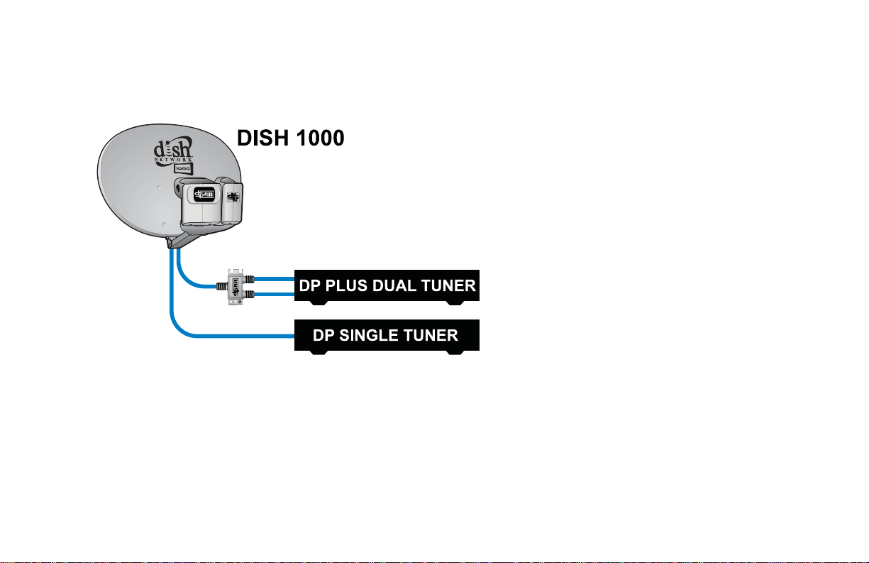
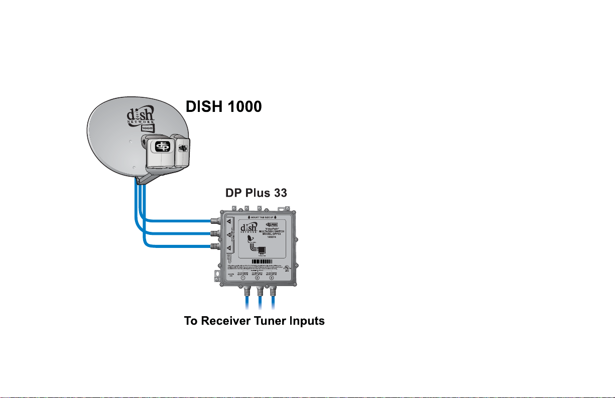
Dish Network DISH 1000 User manual

Dish Network
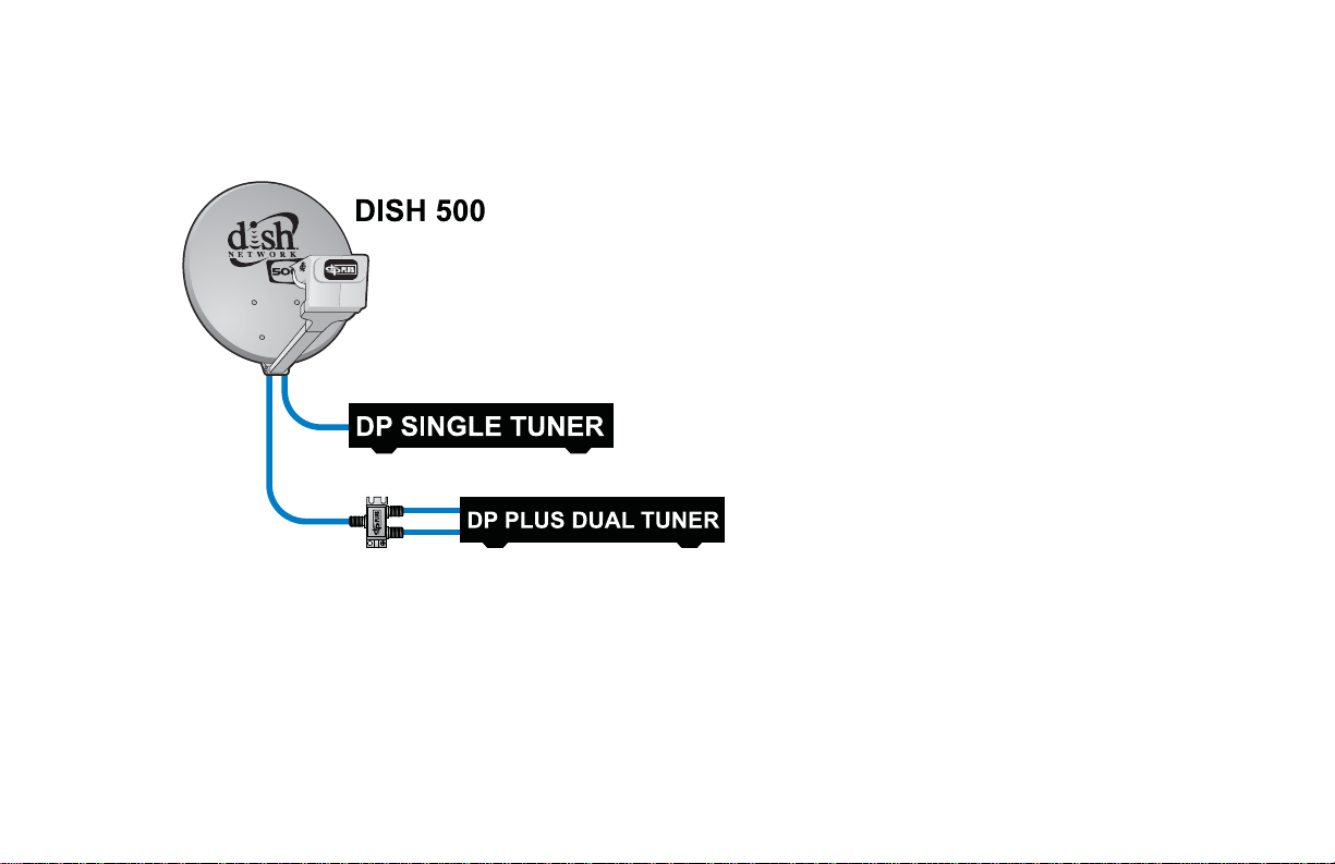
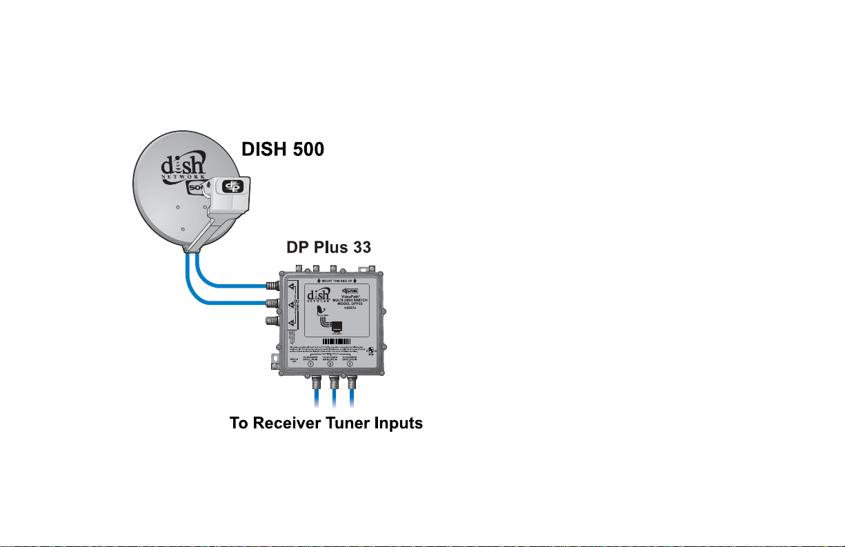
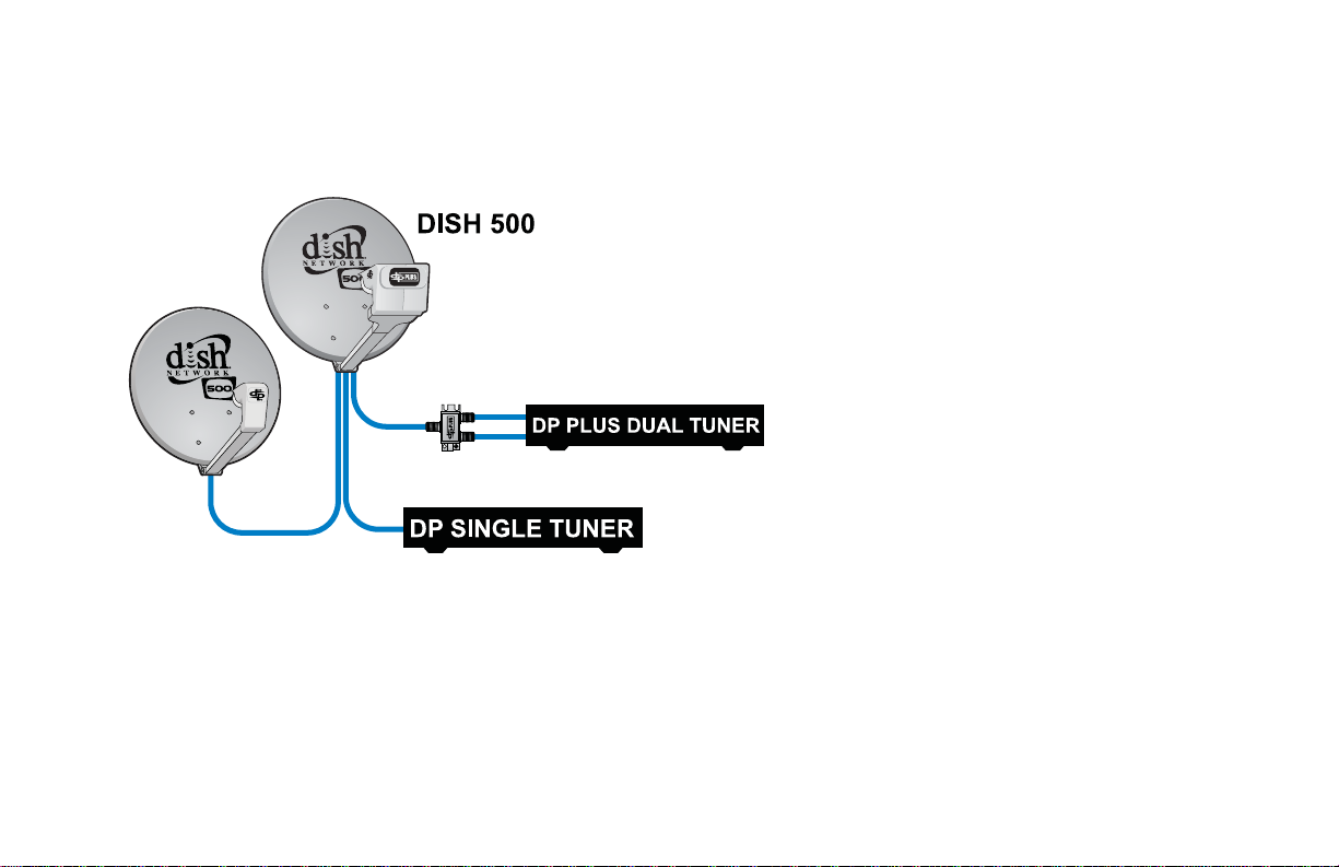
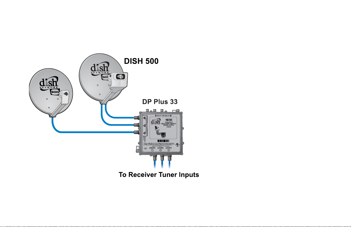
Dish Network DISH 500 User manual

Dish Network
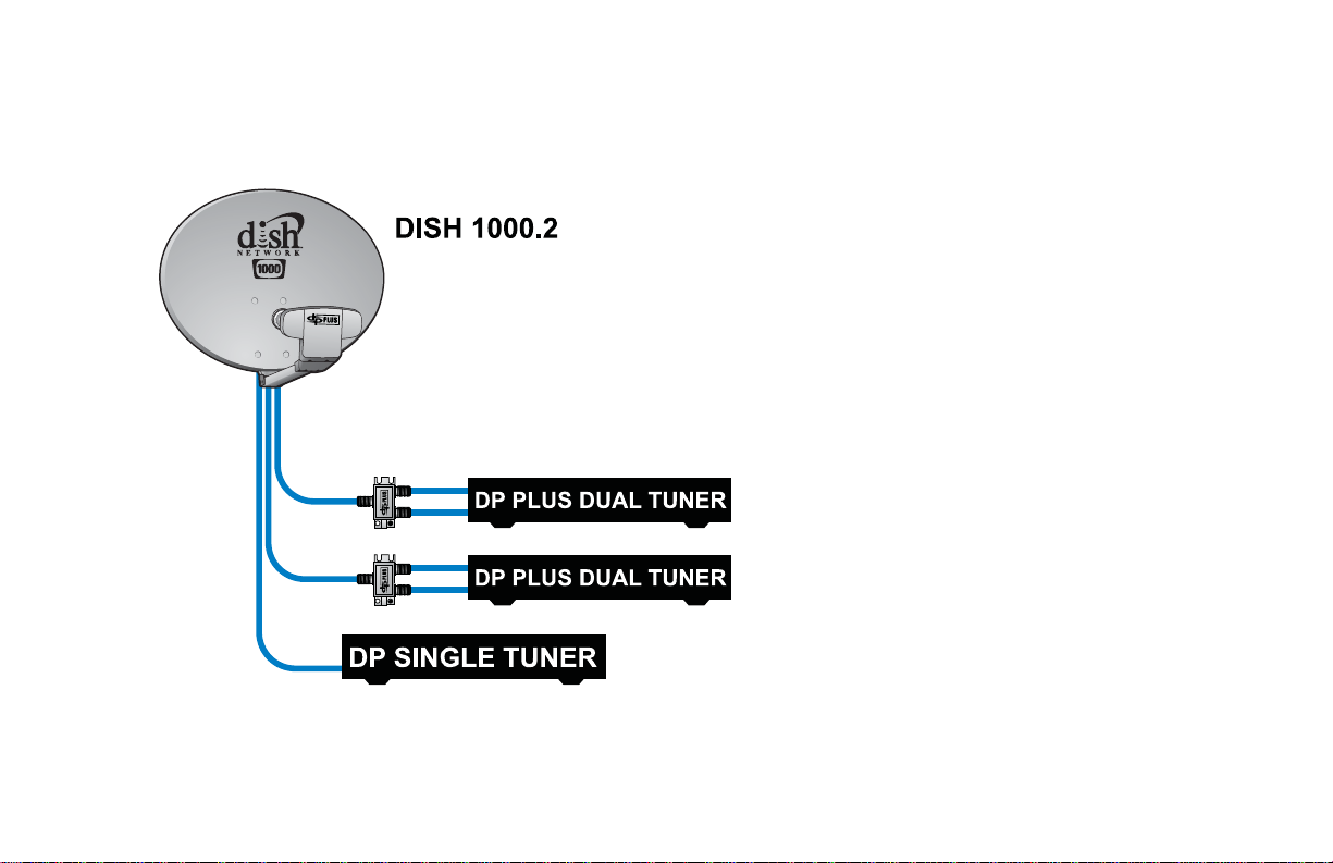
Dish Network DISH 1000.2 User manual

Dish Network
Dish Network D1000.4 EA User manual

Dish Network
Dish Network Playmaker User manual

Dish Network
Dish Network Tailgater User manual

Dish Network
Dish Network DishPro User manual

Dish Network
Dish Network SuperDISH User manual

Dish Network
Dish Network DishPro User manual

Dish Network
Dish Network Tailgater User manual

Popular Antenna manuals by other brands

DAVIS
DAVIS Windex AV 3160 installation instructions

Belden
Belden Hirschmann BAT-ANT-N-14G-IP23 Mounting instruction

Vtronix
Vtronix YHK Fitting instructions

KVH Industries
KVH Industries TracVision 6 Technical manual

Leica Geosystems
Leica Geosystems GS10 user manual

Sirio Antenne
Sirio Antenne Gain-Master manual


Feig Electronic
Feig Electronic ID ISC.ANTH200/200 Series manual

TERK Technologies
TERK Technologies TV44 owner's manual

TERK Technologies
TERK Technologies SIR3 owner's manual

Directive Systems & Engineering
Directive Systems & Engineering DSE2324LYRMK quick start guide

HP
HP J8999A instructions

MobilSat
MobilSat MSP-S Mounting instructions