DISIBEINT dePACK User manual

de
PACK
Instructions on the operation
and co
nfiguration of dePACK
USER MANUAL
Document: manual_
depack
_
es
Revision: 02
PACK
Instructions on the operation
nfiguration of dePACK
disibeint@disibeint.com
www.disibeint.com
DISIBEINT
Segle XX, 91
08032 Barcelona
934 560 995
www.disibeint.com

Manual_dePACK_esMANUAL
DEPACK_EN
www.disibeint.com Pàgina 1 de 26
Content
1 SAFETY AND MAINTENANCE .............................................................................................. 3
1.1 BEFORE STARTING .................................................................................................................................3
1.2 AUTHORIZED PERSONNEL .......................................................................................................................3
1.3 OBJECTIVE OF THE MANUAL ....................................................................................................................4
1.4 NOTICE AGAINST MISUSE .......................................................................................................................4
1.5 GENERAL SAFETY INSTRUCTIONS ..............................................................................................................4
1.6 SAFE USE OF THE EQUIPMENT .................................................................................................................4
1.7 INSTALLATION ......................................................................................................................................5
1.8 MAINTENANCE .....................................................................................................................................5
1.9 RECYCLING ..........................................................................................................................................5
2 GENERAL DESCRIPTION ..................................................................................................... 6
3 MAIN FEATURES ................................................................................................................ 6
4 IDENTIFICATION TAG ......................................................................................................... 7
5 LEDS .................................................................................................................................. 7
6 DIMENSIONS ..................................................................................................................... 8
7 TECHNICAL CHARACTERISTICS ........................................................................................... 8
8 ELECTRICAL CONNECTION ............................................................................................... 10
9 POWER CONNECTOR ....................................................................................................... 11
10 ANTENNA CONNECTOR ................................................................................................ 11
11 ETHERNET CONNECTOR ............................................................................................... 11
12 SIM CARD READER ....................................................................................................... 11
13 RS-232/RS-485 CONNECTOR ........................................................................................ 12
14 CONNECTION EXAMPLES.............................................................................................. 13
14.1 CONDUCTIVE INPUTS .......................................................................................................................... 13
14.2 4-20MA INPUT ................................................................................................................................. 13
14.3 POTENTIOMETRIC INPUT ..................................................................................................................... 13
14.4 PNP INPUTS ..................................................................................................................................... 14
14.5 NAMUR INPUTS ................................................................................................................................. 14
14.6 CAPACITIVE INPUTS ............................................................................................................................ 14
15 CONNECT TO THE SAME NETWORK AS DEPACK ............................................................ 15
15.1 WI-FI .............................................................................................................................................. 15
15.2 ETHERNET ........................................................................................................................................ 15
15.3 ETHERNET POINT TO POINT.................................................................................................................. 15
15.4 ACCESS POINT ................................................................................................................................... 15
16 ACCESS NODE-RED ....................................................................................................... 16
17 ACCESS TO DASHBOARD .............................................................................................. 17
18 ACCESS TO WEBADMIN (CONFIGURATOR) ................................................................... 18

Manual_dePACK_esMANUAL
DEPACK_EN
www.disibeint.com Pàgina 2 de 26
19 WI-FI CONFIGURATION ................................................................................................ 19
19.1 STA MODE ....................................................................................................................................... 19
19.2 AP MODE ......................................................................................................................................... 20
20 ETHERNET .................................................................................................................... 21
21 GPRS CONFIGURATION ................................................................................................ 22
21.1 OPERATOR APNS TABLE ..................................................................................................................... 25

Manual_dePACK_esMANUAL
DEPACK_EN
www.disibeint.com Pàgina 3 de 26
1 Safety and maintenance
These instructions provide necessary information for assembly, connection, commissioning, and
configuration, as well as important information for maintenance, troubleshooting, and user safety. For
this reason, it is necessary to read it before start-up and always keep it close at hand in the vicinity of the
equipment as an integral part of the product.
1.1 Before starting
Please read these instructions before unpacking and putting the instrument inside into operation. Follow
the instructions as described in this document.
The equipment must only be handled by qualified personnel, familiar with this type of instructions and in
accordance with the specific health, safety and accident prevention regulations regulated for the area
where it is located.
Attention:
The sections indicated with this symbol must be read carefully.
This symbol indicates danger of electric shock.
This symbol indicates that the equipment is protected by double insulation.
Equipment under European directive 2012/19/EC. At the end of its useful life, do not leave
the equipment in a household waste container. It is necessary to follow the local regulations
regarding the recycling of electronic equipment.
Complies with the relevant European directive.
1.2 Authorized personnel
All the operations described in this documentation must be carried out exclusively by qualified personnel
authorized by the owner of the installation. During work on and with the device it is always necessary to
use the necessary protective equipment.

Manual_dePACK_esMANUAL
DEPACK_EN
1.3 Obje
ctive of the manual
This manual explains the general guidelines that must be considered for the installatio
correct operation of dePACK. Contact us if you need more information.
1.4
Notice against misuse
In the event of inappropriate or unforeseen use of this equipment, it is possible that specific risks for each
application may arise from it, for
This may result in material, personal or environmental damage. The computer's protection properties
may also be affected.
1.5
General safety instructions
The equipment corresponds to the le
and directives in force. The operation of this equipment is only allowed in an impeccable and safe
technical state.
The owner is responsible for the perfect functioning of the equipment.
corrosive environments in which a malfunction of the equipment may give rise to possible risks, the
owner must guarantee the correct operation of the equipment by taking the appropriate measures.
The user must comply with t
he safety instructions in this instruction manual, the specific installation
regulations of each country and the current safety and accident prevention regulations.
For security and guarantee reasons, any manipulation that goes beyond what is described in
instruction manual must be carried out by personnel authorized by the manufacturer. Remodeling or
changes carried out on your own are explicitly prohibited.
1.6
Safe use of the equipment
Risk of injury!
• Disconnect power from the equipment before ha
• Operate the equipment only if it is in an impeccable technical condition, without
errors or failures.
• The person responsible for handling the equipment without interference is the operator.
www.disibeint.com
ctive of the manual
This manual explains the general guidelines that must be considered for the installatio
correct operation of dePACK. Contact us if you need more information.
Notice against misuse
In the event of inappropriate or unforeseen use of this equipment, it is possible that specific risks for each
application may arise from it, for
example, a tank overflow due to poor assembly or poor configuration.
This may result in material, personal or environmental damage. The computer's protection properties
General safety instructions
The equipment corresponds to the le
vel of technical development under consideration of the regulations
and directives in force. The operation of this equipment is only allowed in an impeccable and safe
The owner is responsible for the perfect functioning of the equipment.
In case of use in aggressive or
corrosive environments in which a malfunction of the equipment may give rise to possible risks, the
owner must guarantee the correct operation of the equipment by taking the appropriate measures.
he safety instructions in this instruction manual, the specific installation
regulations of each country and the current safety and accident prevention regulations.
For security and guarantee reasons, any manipulation that goes beyond what is described in
instruction manual must be carried out by personnel authorized by the manufacturer. Remodeling or
changes carried out on your own are explicitly prohibited.
Safe use of the equipment
• Disconnect power from the equipment before ha
ndling it.
• Operate the equipment only if it is in an impeccable technical condition, without
• The person responsible for handling the equipment without interference is the operator.
Pàgina 4 de 26
This manual explains the general guidelines that must be considered for the installatio
n, start-up and
In the event of inappropriate or unforeseen use of this equipment, it is possible that specific risks for each
example, a tank overflow due to poor assembly or poor configuration.
This may result in material, personal or environmental damage. The computer's protection properties
vel of technical development under consideration of the regulations
and directives in force. The operation of this equipment is only allowed in an impeccable and safe
In case of use in aggressive or
corrosive environments in which a malfunction of the equipment may give rise to possible risks, the
owner must guarantee the correct operation of the equipment by taking the appropriate measures.
he safety instructions in this instruction manual, the specific installation
regulations of each country and the current safety and accident prevention regulations.
For security and guarantee reasons, any manipulation that goes beyond what is described in
the
instruction manual must be carried out by personnel authorized by the manufacturer. Remodeling or
• Operate the equipment only if it is in an impeccable technical condition, without
• The person responsible for handling the equipment without interference is the operator.

Manual_dePACK_esMANUAL
DEPACK_EN
1.7 Installation
The installation of the equip
ment is carried out on a DIN rail, leaving all the connections inside an
electrical panel. The equipment must be connected to a power supply circuit protected with type gl (IEC
269) or type M fuses, between 0.5 and 2 A. It must be fitted with a magnetother
device to disconnect the equipment from the power supply network. The power supply and voltage
measurement circuit must be connected with a cable with a minimum section of 1 mm².
Do not install the equipment inside a metallic box
and WiFi), as this would make it difficult for it to function correctly.
1.8 Maintenance
Remove dirt from the box from time to time.
When carrying out cleaning, keep the following in mind:
• Disconnect
power from the equipment before handling it.
• Only use cleaning agents that do not damage the casing, the type plate or the seals.
• Use only cleaning methods that correspond to the degree of protection.
1.9 Recycling
The packaging is made of cardboard an
Eliminate waste packaging material produced through specialized recycling companies.
Electronic products can NOT be thrown away because they are recyclable, in addition to their impact on
the environment.
Hand over the equipment directly to a specialized recycling company and do not use municipal collection
points for this.
First remove any batteries that may be present, whenever possible to remove them from the equipment,
and proceed to dispose of
them separately in the proper manner.
www.disibeint.com
ment is carried out on a DIN rail, leaving all the connections inside an
electrical panel. The equipment must be connected to a power supply circuit protected with type gl (IEC
269) or type M fuses, between 0.5 and 2 A. It must be fitted with a magnetother
mal switch or equivalent
device to disconnect the equipment from the power supply network. The power supply and voltage
measurement circuit must be connected with a cable with a minimum section of 1 mm².
Do not install the equipment inside a metallic box
in case you want to use wireless communications (GPRS
and WiFi), as this would make it difficult for it to function correctly.
Remove dirt from the box from time to time.
When carrying out cleaning, keep the following in mind:
power from the equipment before handling it.
• Only use cleaning agents that do not damage the casing, the type plate or the seals.
• Use only cleaning methods that correspond to the degree of protection.
The packaging is made of cardboard an
d wood, compatible with the environment and recyclable.
Eliminate waste packaging material produced through specialized recycling companies.
Electronic products can NOT be thrown away because they are recyclable, in addition to their impact on
Hand over the equipment directly to a specialized recycling company and do not use municipal collection
First remove any batteries that may be present, whenever possible to remove them from the equipment,
them separately in the proper manner.
Pàgina 5 de 26
ment is carried out on a DIN rail, leaving all the connections inside an
electrical panel. The equipment must be connected to a power supply circuit protected with type gl (IEC
mal switch or equivalent
device to disconnect the equipment from the power supply network. The power supply and voltage
measurement circuit must be connected with a cable with a minimum section of 1 mm².
in case you want to use wireless communications (GPRS
• Only use cleaning agents that do not damage the casing, the type plate or the seals.
• Use only cleaning methods that correspond to the degree of protection.
d wood, compatible with the environment and recyclable.
Eliminate waste packaging material produced through specialized recycling companies.
Electronic products can NOT be thrown away because they are recyclable, in addition to their impact on
Hand over the equipment directly to a specialized recycling company and do not use municipal collection
First remove any batteries that may be present, whenever possible to remove them from the equipment,

Manual_dePACK_esMANUAL
DEPACK_EN
2
General description
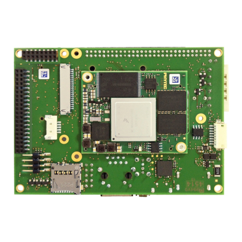
dePACK is an industrial IoT controller equipped with a high
control unit with a fully integrated Yocto Linux system and Node
software.
The device includes RS-
232/485 serial
network interface, and quad
communications. Ideal for fog computing applications where it is required
to monitor, control and send data.
Regarding inputs, it contains Conductive, PNP, Namur, 4.
potentiometric and capacitive to connect the necessary sensors for a
multitude of applications.
3 Main features
ARM CORTEX-
A7 700 Mhz.
256 MB DDR3 memory.
512 MB NAND flash memory
High performance embedded system integrated with Linux Yocto
GPRS, dig
ital and analog I/O of different types
Wifi.
RS-232/485 from 9600 to
10/100Mbps
Ethernet port
Node-RED integrated.
www.disibeint.com
General description
dePACK is an industrial IoT controller equipped with a high
-performance
control unit with a fully integrated Yocto Linux system and Node
-RED
232/485 serial
communications, 10/100 Ethernet
network interface, and quad
-band GPRS and Wi-Fi wireless
communications. Ideal for fog computing applications where it is required
to monitor, control and send data.
Regarding inputs, it contains Conductive, PNP, Namur, 4.
.20mA,
potentiometric and capacitive to connect the necessary sensors for a
A7 700 Mhz.
512 MB NAND flash memory
High performance embedded system integrated with Linux Yocto
ital and analog I/O of different types
.
115200 bps.
Ethernet port
.
Pàgina 6 de 26

Manual_dePACK_esMANUAL
DEPACK_EN
4 Identification tag
5 Leds
Led
Power
RS
-
232/RS
-
485
Modem
S/Ix
S4
www.disibeint.com
Description
On: Green
Data transmission: Red
Data reception: Green
Data transmission: Red
Data reception: Green
If Sx= True and Ix = False: Green
If Sx= False and Ix = True: Blue
If Sx= True and Ix = True: White
If S4= True: Green
Pàgina 7 de 26
Description
On: Green
Data transmission: Red
Data reception: Green
Data transmission: Red
Data reception: Green
If Sx= True and Ix = False: Green
If Sx= False and Ix = True: Blue
If Sx= True and Ix = True: White
If S4= True: Green

Manual_dePACK_esMANUAL
DEPACK_EN
6 Dimensions
7
Technical characteris
Electrical data
Power supply
Frequency
Maximum consumption
Control unit
CPU
RAM
memory
Flash
memory
Clock
Environmental conditions
Temperature
Humidity
Maximum working altitude
Mechanical data
Surround material
Protection degree
Dimensions
Weight
Mo
unting
Characteristics and electrical
safety
E
lectrical safety
Electric shock protection
Isolation
www.disibeint.com
Technical characteris
tics
85 .. 264 V
AC
47 .. 63 Hz
4,6 .. 7,5 VA
ARM Cortex
-
A7 700 MHz
256 MB DDR3
512 MB NAND
RTC with battery to save time
-
20 .. +50 ºC
5 % .. 95 %
2000 m
UL94
-
V0 self
-
extinguishing plastic
IP20
105 x 88,5 x 48mm
180 g
DIN
rail
CAT III 300 V according to EN 61010
Double insulation class II
3 kVCA
Pàgina 8 de 26

Manual_dePACK_esMANUAL
DEPACK_EN
www.disibeint.com Pàgina 9 de 26
Serial interface
Type
RS
-
485 three threads (A+/S GND/ B
-
) (RX/GND/TX)
Transmission speed
9600 / 19200 bps configurable
Wir
eless interface
Wi
-
Fi
802.11 b/g/n (2,4 GHz)
Network interface
Type
Ethernet
Speed
10/100 Mbps
Conductive inputs
Number and type
5 inputs for conductive probes
Resolution
12 bits (4096 points)
Configurable inputs
Number and type
4 configurable
inputs for Namur, PNP and capacitive sensors
Resolution
12 bits (4096 points)
Analog input (AI0)
Number and type
1 analog input 0...20 mA / 4...20 mA
Resolution
12 bits (4096 points)
Potentiometric input (AI1)
Number and type
1 Potentiometric inpu
t
Resolution
12 bits (4096 points)
Voltage outputs
Voltage
2 of 8V2 and 1 of 24V
Regulations
IEC 60664, VDE 0110, UL 94, EN
-
61010
-
1, EN 55011, EN 61000
-
4
-
3,
EN 61000-4-11, EN 61000-6-4, EN 61000-4-2, EN 61000-6-2, EN
61000-6-1, EN 61000-6-3, EN 61000-4-5 -CE

Manual_dePACK_esMANUAL
DEPACK_EN
8
Electrical connection
www.disibeint.com
Electrical connection
Pàgina 10 de 26

Manual_dePACK_esMANUAL
DEPACK_EN
9 Power connector
It can be powered with single-
phase or three
Single phase: wire V3 and N
Three-phase:
wire connectors V1, V2, V3 and
10 Antenna connector
To install the external antenna, simp
11 Ethernet connector
The equipment has an Ethernet port that allows access to dePACK from the outside.
12 SIM card reader
dePACK requires a SIM card (1FF) to operate on a mobile network.
The SIM card reader slot is located
holder. To insert a SIM card, insert the card with the contacts facing up and the shorter end in. The card
should not protrude once it has been inserted correctly.
Once the SIM card is
installed, you can enable mobile data connectivity.
www.disibeint.com
phase or three
-phase connection:
Single phase: wire V3 and N
wire connectors V1, V2, V3 and
N.
To install the external antenna, simp
ly screw the connector clockwise.
The equipment has an Ethernet port that allows access to dePACK from the outside.
dePACK requires a SIM card (1FF) to operate on a mobile network.
The SIM card reader slot is located
on the back of dePACK. A SIM card must be inserted into the SIM card
holder. To insert a SIM card, insert the card with the contacts facing up and the shorter end in. The card
should not protrude once it has been inserted correctly.
installed, you can enable mobile data connectivity.
Pàgina 11 de 26
The equipment has an Ethernet port that allows access to dePACK from the outside.
on the back of dePACK. A SIM card must be inserted into the SIM card
holder. To insert a SIM card, insert the card with the contacts facing up and the shorter end in. The card

Manual_dePACK_esMANUAL
DEPACK_EN
www.disibeint.com Pàgina 12 de 26
13 RS-232/RS-485 connector
To use RS232 or RS485 follow the connection diagram:
In this example, an SBL8 230 with RS-485 communication is connected to the dePACK Modbus connector.
This connection must be made using a shielded cable to connect the shield to the dePACK GND, the other
end of the shield must not be connected.

Manual_dePACK_esMANUAL
DEPACK_EN
14
Connection examples
14.1 Conductive inputs
Example connection of a two-
contact NR conductive
probe.
C1 = Contact 1
C2 = Contact 2
CMN = Common
14.2 4-20mA Input
Example
connection of a TMN magnetic transducer with
4-20 mA output.
+ = Positive
AO = 4-20 mA output
- = Negative
14.3 Potentiometric input
Example
connection of a TMR magnetic transducer
with potentiometric output.
+ = Positive
AO = Potentiometric output
- = Negative
www.disibeint.com
Connection examples
contact NR conductive
connection of a TMN magnetic transducer with
connection of a TMR magnetic transducer
Pàgina 13 de 26

Manual_dePACK_esMANUAL
DEPACK_EN
14.4 PNP inputs
Example
connection of a SCM capacitive sensor with
PNP/NPN output.
To use PNP inputs, the Ix inputs must be configured using
Node-RED to be of this type.
+ = Positive
NO = Normally open PNP output
- = Negative
14.5 Namur inputs
Example
connection of an inductive sensor with Namur
output.
To use Namur inputs, the Ix inputs must be configured using
Node-RED to be of this type.
+ = Positive
NO = Exit Namur
- = Negative
14.6 Capacitive inputs
Example
connection of a capacitive sensor.
To use Capacitive inputs, the Ix inputs must be configured using
Node-RED to be of this type.
+ = Positive
- = Negative
www.disibeint.com
connection of a SCM capacitive sensor with
To use PNP inputs, the Ix inputs must be configured using
connection of an inductive sensor with Namur
To use Namur inputs, the Ix inputs must be configured using
connection of a capacitive sensor.
To use Capacitive inputs, the Ix inputs must be configured using
Pàgina 14 de 26

Manual_dePACK_esMANUAL
DEPACK_EN
www.disibeint.com Pàgina 15 de 26
15 Connect to the same network as dePACK
To connect to dePACK it is necessary that the device from which you want to connect (PC, mobile, etc..) is
in the same network as dePACK. There are 4 different ways to do this:
15.1 Wi-Fi
If you connect dePACK to a Wi-Fi network, the router will assign you an IP (E.g. 192.168.1.34). Your device
must be connected to the same network as dePACK in order to interact with each other.
15.2 Ethernet
If you connect dePACK to a network via Ethernet, the dePACK router will assign you an IP (E.g.
192.168.1.34). Your device must be connected to the same network as dePACK in order to interact with
each other.
15.3 Ethernet point to point
If a device is connected directly to dePACK via an Ethernet cable, it generates a network in which its IP is
10.1.10.1. To interact with dePACK you must change the IP of your device to 10.1.10.x (i.e. 10.1.10.10).
15.4 Access point
dePACK comes from the factory in ´Access point´ mode. In this mode, dePACK generates its own Wi-Fi
network to which the device can connect to communicate. In this network, the IP 192.168.137.1 is
assigned to dePACK by default.

Manual_dePACK_esMANUAL
DEPACK_EN
www.disibeint.com Pàgina 16 de 26
16 Access Node-RED
Node-RED is the tool with which dePACK is programmed.
To access Node-RED our device must be on the same network as dePACK. There are two options to
access:
Write the address in the browser: dePACK-xxxxxx:1880
Being xxxxxx the last 6 characters of the dePACK MAC
If the IP address on the network of dePACK is known, write the address in the browser “ip”:1880

Manual_dePACK_esMANUAL
DEPACK_EN
www.disibeint.com Pàgina 17 de 26
17 Access to dashboard
The control panel is the portal from which the status of the application running in dePACK is viewed and
controlled.
To access the control panel our device must be on the same network as dePACK. There are two options to
access:
Write the address on the browser: dePACK-xxxxxx:1880/ui
Being xxxxxx the last 6 characters of the dePACK MAC
If the IP address on the network of dePACK is known, write the address in the browser:
“ip”:1880/ui

Manual_dePACK_esMANUAL
DEPACK_EN
www.disibeint.com Pàgina 18 de 26
18 Access to WebAdmin (Configurator)
WebAdmin is the portal from which all Wi-Fi and Ethernet settings of the dePACK are viewed and
configured.
To access WebAdmin our device must be on the same network as dePACK. There are two options to
access:
Write the address in the browser: dePACK-xxxxxx:80
Being xxxxxx the last 6 characters of the dePACK MAC.
If the IP address of the dePACK is known on the network, write the address in the browser:
“ip”:80
Once in the WebAdmin, it asks us for a username and a password.
- Username: admin
- Password: depack

Manual_dePACK_esMANUAL
DEPACK_EN
www.disibeint.com Pàgina 19 de 26
19 Wi-Fi configuration
The dePACK Wi-Fi settings are found and modified in WebAdmin. It has two Wi-Fi modes: STA mode and
AP mode.
19.1 STA mode
In this mode, dePACK connects to an external Wi-Fi network.
1. To configure the STA mode, you must access the WebAdmin (review the section “Access to
WebAdmin”).
2. Once inside the WebAdmin, you must select the “Network settings” section and within it the
“WiFi” box.
3. Then select the Station mode.
4. Scan available Wi-Fi networks and select the desired one.
5. Finally enter the Wi-Fi network password and save the changes.
Table of contents
