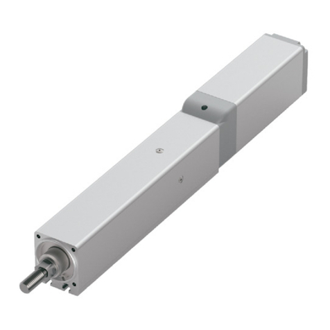
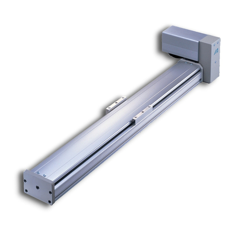
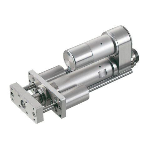
IAI ELECYLINDER EC-WS10 R Series User manual

www.intelligentactuator.com

▲
Wide Slider Type
Supports High Load Moment and Large Overhang
The wide body is equipped with a built-in ball circulating type linear guide. It is most
suitable to heavy workpieces and large overhang applications.
▲Transfer of corrugated cardboard boxes
X-axis: EC-EWS12M-600
Since AVD (Acceleration, Velocity and
Deceleration) can be individually set up,
vibration will be suppressed and cycle times
can be shortened.
* The "Unit Change" enables display of the actual units (speed: mm/s and acceleration: G).
Easy data setting screen
Velocity (%) Velocity (%)
Velocity Velocity
Easy data setting
Deceleration (%) Deceleration (%)
Deceleration Deceleration
Operating condition (forward: backward end to forward end) Operating condition (backward: forward end to backward end)
Speed Speed
Acceleration (%) Acceleration (%)
Acceleration Acceleration
Push Push
Cycle time Cycle time
Time Time
Jog
Present position
Forward end
Position setting
Backward end
Manual operation
Inching
Backward end
Unit change
Forward end
(home position side)
Display switch
Trial run
40kg
Because heavy workpieces
can be overhung, the
equipment can be made
smaller.
Mc 176N·m
Dynamic allowable moment
(Rolling direction)
WideWide
sliderslider
Wide
slider
A linear guide integrated
with the base is used.
→It achieves high rigidity.
Linear guide
Base sectional view
OverhangOverhang
500500mmmm
Overhang
500mm
In addition…
1

Ball screw
Ball circulating type
linear guide
(same as the opposite side)
Motor
Controller
Stainless sheet
Positioning of two points Built-in controller
All-in-one
Side mounted motor type
The side mounted motor type is suitable for limited space in the longitudinal direction.
All necessary functions
for a single axis are
built-in including
controller and teaching
functions.
▲Lifter transfer of parts container boxes
Z-axis: EC-DWS12MR-800
Designing, start up and
adjustment times can be
shortened.
Wide
Type
Digital speed controller
Motion setting
Trial run
Cycle time checking
The
ELECYLINDER
main unit
can do all of these !
・
・
・
・
・
・
Example of in-house manufacturing a direct-acting unit
Greater number of parts and man-hours
Ball screw
Two linear guides
Guide block
Motor
Coupling
Plate
Bearing
Assembling
Designing
Servo adjustment
Wide slider type ELECYLINDER
product page to view the demo video:
2

EC - - - -
Series
Digital speed controller
Type Lead Specication Stroke
Power / I/O cable length
Options
Blank
Motor straight
R
Side mounted
motor
Blank
Incremental encoder specification
NPN specification, no options
ACR
RCON-EC connection specification*1
BBrake
CS Air cylinder mounting plate
DL Digital speed controller
installation direction (left)*2
DR Digital speed controller
installation direction (right)*2
G1/G5
Designated grease
specification
*3
ML Motor side mounted to the
left*4
MR Motor side mounted to the
right*4
NM Non-motor end specification
PN PNP specification*1
SR Slider part roller specification
TMD2 Split motor and controller
power supply specification
WA Battery-less absolute
encoder specification
WL
Wireless communication specification
WL2
Wireless axis operation specification
Model Specification Items
ELECYLINDER® Wider Slider Type
WS10
Wide slider 100mm width
WS12
Wide slider 120mm width
Blank Without digital
speed controller
DWith digital
speed controller
<(D)WS10> <(D)WS12>
SLead 20mm SLead 24mm
HLead 12mm HLead 16mm
MLead 6mm MLead 8mm
LLead 3mm LLead 4mm
<(D)WS10> <(D)WS12>
50 50mm 50 50mm
~
~
~
~
500
500mm
800
800mm
(Every 50mm)
*1 "PN" and "TMD2" cannot be selected if
"ACR" is selected
*2 Please be sure to select a code if
selecting the specification with digital
speed controller
*3 For the side mounted motor
specification, G1 cannot be selected
*4 Selection is possible (and required) only
for the side mounted motor
specification
(S): 4-way connector cable
(Note) A power I/O connector is
not included if RCON-EC
connection specification
(ACR) is selected
0
Without cable
Power I/O connector
included (Note)
(S)1 1m
~
~
(S)10 10m
(Every 1m)
3
ECELECYLINDER®

Energy saving setting
ELECYLINDER® can select enable/disable of the "Energy saving" in parameter (No. 8).
Enable setting reduces power capacity by up to approx. 40% compared with the disable setting.
However, the max. speed, max. acceleration/deceleration and payload will become smaller than that for the disable setting.
Disable setting increases max. speed, max. acceleration/deceleration and payload compared with the enabled setting.
Refer to the "Payload Table by Speed and Acceleration" and "Stroke and max. Speed" table of each product's specification page.
The product is set to disabled for shipment.
Mode Parameter name/
description Features
Power mode Energy saving disabled High specification
Energy saving mode Energy saving enabled High energy saving effect
Setting for
shipment
Specication
Type
Lead Stroke (mm) and max. speed (mm/s)
* Band length=stroke *Numbers in band = Max. speed by stroke, Numbers in < > are when used vertically.
Max.
payload
Reference
page
Model mm
50 100 150 200 250 300 350 400 450 500 550 600 650 700 750 800
Motor
straight
(D)WS10
S 20 4 —
P7
H 12 15 —
M 6 25 4
L 3 44 7
(D)WS12
S 24 10 —
P11
H 16 20 —
M 8 40 8
L 4 62 13.5
Side
mounted
motor
(D)WS10□R
S 20 4 —
P15
H 12 15 —
M 6 25 4
L 3 44 7
(D)WS12□R
S 24 10 —
P19
H 16 20 —
M 8 40 8
L 4 62 13.5
900 480600700800
135 607080110
900 480600700800
640 280320400480560
720 200220240280320360420500580640
720 200220240280320360420500580640
160 607080110135
640 280320400480560
420
<360> 8590110130150170190220250280360
420
<280> 8590110130150170190220250280
360
<280>
210
<140> 45505565758595110125140
180
<140>
210 45505565758595110125140180
400 <360> 120140180210270360
400 <320> 120140180210270
360
<320>
1000 360500 460 400580700800900
1000 360500 460 400580700800900
Table of Specifications
Horizontal
Vertical
4
ECELECYLINDER®

Mounting orientation
Series Type Horizontal mounting on flat
surface Vertical mounting Horizontal mounting to side Horizontal mounting
suspended
EC
(D)WS10(□R)
○ ○ ○ ○
(D)WS12(□R)
*1 When mounting vertically, make sure to install the motor on the top.
Installing with the motor on the bottom could cause grease to separate and base oil to leak into the motor, which could cause controller or motor encoder failure.
It is therefore not recommended to install the motor on the bottom side.
*2 If installing with the motor on the top, attach a cap to the teaching port.
It could cause failure if foreign matter becomes clogged.
*3 Not supported when selecting the air cylinder mounting plate (CS) option.
*4 Lead S and H are not supported.
*5 Installing the product horizontal to side or horizontal suspended may cause slack or misalignment in the stainless steel sheet.
Continuing to use it this way could cause the stainless steel sheet to break. Please inspect it daily and adjust the sheet if any slack or misalignment is found.
Precautions for installation
Overhang load length
Keep the body installation surface and parts mounting surface flatness within 0.05mm/m.
Uneven flatness will increase the sliding resistance of the slider and may cause a malfunction.
The bottom surface and the left side (when viewed from the opposite side of the motor) of the main body base are the reference surfaces
for the slider travel accuracy.
This is the guideline of offset lengths for smooth operations of the
actuator, when a workpiece or a bracket is mounted offset from the
actuator slider.
If the offset length greatly exceeds the guideline, it may cause failure due
to vibration and the like.
Use the actuator within the guideline for the offset length.
When mounting using the side surface as reference, machining of the
surfaces should be done according to the drawing below.
Reference surface Base bottom surface
Effective range of reference surface
R 0.3 or less
A(mm)
3~5
L
Ma
L
Mb
Mc
: Can be mounted
*3
*5
*3
*5
*1
*2
*3
*4
Mounting method
5
ECELECYLINDER®

Mounting method
Using the through holes on the base
Using the air cylinder compatible plate
There are some through holes on the base so that it can be fixed from the top.
When the optional "air cylinder compatible mounting plate (type: CS)" is selected, mounting plates on the slider and base sides are
included.
The mounting holes, positions and main body height can be aligned with some types of rod-less air cylinders (*)
<Dimensions of the reamed hole and the oblong hole positions>
<Dimensions of through holes>
* Refer to the "Dimensions" in respective product pages for the details of the positions.
* Contact IAI representatives for details.
Type Bolt size Counterbored through
holes (mm)
A
(mm)
B
(mm)
Reamed hole
(mm)
Oblong hole
(mm)
(D)WS10(□R)
M5
φ5.5 through
φ9.5 deep counterbored,
depth 6.5
84 25.5 φ5H7
Depth 5
C
:
5
+0.0012
0
D
:
6,depth 5
(D)WS12(□R)
M6
φ6.6 through
φ11deep counterbored,
depth 6.5
103 30 φ6H7
Depth 6
C
:
6
+0.0012
0
D
:
7,dept 6
Oblong hole
Through hole Reamed hole
Reference surface
Counterbored through holes Reamed hole Oblong hole
Base side plate
Slider side plate
●Notes
• When optional "air cylinder compatible mounting plate (CS)"
is selected, the payload will be reduced by 1 kg.
• Vertical, side and ceiling mounting are not possible.
<Body mounting> <Transported object mounting>
Actuator mounting
hex socket bolt (accessory)
Air cylinder
mounting plate (base side)
Insert square nut (accessory)
into T-slot
Mounting plate
hex socket bolt (accessory)
Positioning pin (accessory)
Air cylinder
mounting plate (slider side)
Mounting method 6
ECELECYLINDER®

EC-WS10
EC-DWS10 <With digital speed controller>
■Model Specification Items
EC - - - -
Series - Type Lead - Stroke - Power • I/O cable length - Options
WS10 Standard S20mm 50 50mm See power • I/O cable length
below
See options
below
DWS10 Digital speed controller H12mm
~
~
M6mm 500 500mm
L3mm (Every 50mm)
デジタルスピコン
■Stroke
Stroke
(mm) WS10 DWS10 Stroke
(mm) WS10 DWS10
50 300
100 350
150 400
200 450
250 500
Selection
Notes
(1) The maximum speed decreases as the stroke becomes longer
due to the dangerous number of rotation of the ball screw.
Confirm the maximum speed, referring to the “Stroke and Max.
Speed” of the desired stroke.
(2) “Main Specifications” displays the payload’s maximum value. If
the energy-saving setting is enabled, the main specifications will
change. Please refer to “Table of Payload by Speed/Acceleration”
for details.
(3) If performing push-motion operations, refer to the“Correlation
between Torque and Current Limit” diagram. The torques listed
are only reference values. Refer to P. 26 for precautions.
(4) Pay close attention to the installation orientation.
Please refer to P. 5 for details.
(5) The “H” and “S” leads cannot be vertically mounted.
(6) Reference value of the overhang load length is under 400mm in
the Ma, Mb, and Mc directions. Refer to descriptions about the
overhang length on P. 5.
(7) The center of gravity of the attached object should be less than
1/2 of the overhang distance. Even when the overhang distance
and load moment are within the allowable range, the operating
conditions should be moderated if some abnormal vibration or
noise is observed.
■Options
Name Option code
Reference page
RCON-EC connection specification (Note 1) ACR 23
Brake B23
Air cylinder mounting plate CS 23
Digital speed controller installation direction (left) (Note 2)
DL 24
Digital speed controller installation direction (right) (Note 2)
DR 24
Designated grease specification
(Note 3)
G1/G5 25
Non-motor end specification NM 25
PNP specification PN 25
Slider part roller specification SR 25
Split motor and controller power supply specification TMD2 25
Battery-less
absolute encoder specification WA 25
Wireless communication specification WL 25
Wireless axis operation specification WL2 25
(Note 1) If the RCON-EC connection specification (ACR) is selected, the PNP specification
(PN) and split motor and controller power supply specification (TMD2) cannot be
selected.
(Note 2) Available only for DWS10. Be sure to enter a model in the options section of the
model number.
(Note 3) When using Lead 3 in a vertical mount, the max. speed is 110mm/s if the
specified grease specification (G1) is selected.
■Power · I/O cable length
■Standard connector cable
Cable code Cable
length
User wiring specification
(flying leads)
RCON-EC connection specification (Note 5)
(with connectors on both ends)
CB-EC-PWBIO£££-RB
supplied
CB-REC-PWBIO£££-RB
supplied
0No cable (Note 4)
1 ~ 3 1 ~ 3m
4 ~ 5 4 ~ 5m
6 ~ 7 6 ~ 7m
8 ~ 10 8 ~ 10m
(Note 4) Only terminal block connector is included. Please refer to P. 31 for details.
(Note 5) If RCON-EC connection specification (ACR) is selected as an option.
(Note) Robot cable is standard.
■4-way connector cable
Cable code Cable
length
User wiring specification
(flying leads)
RCON-EC connection specification (Note 6)
(with connectors on both ends)
CB-EC2-PWBIO£££-RB
supplied
CB-REC2-PWBIO£££-RB
supplied
S1 ~ S3 1 ~ 3m
S4 ~ S5 4 ~ 5m
S6 ~ S7 6 ~ 7m
S8 ~ S10 8 ~ 10m
(Note 6) If RCON-EC connection specification (ACR) is selected as an option.
(Note) Robot cable is standard.
24V
Stepper
Motor
Body Width
100
mm
Coupled
Motor
Simple
Dust-
proof
Horizontal
Vertical
Side
Ceiling
EC-WS10/DWS10
Digital speed controller
EC-WS10 EC-DWS10
7
ECELECYLINDER®
Item Description
Lead Ball screw lead (mm) 20 12 6 3
Horizontal
Payload
Max. payload (kg) (energy-saving disabled)
4 15 25 44
Max. payload (kg) (energy-saving enabled)
4 15 25 40
Speed /
acceleration/
deceleration
Max. speed (mm/s) 900 640 400 160
Min. speed (mm/s) 25 15 8 4
Rated acceleration/deceleration (G)
0.3 0.3 0.3 0.3
Max. acceleration/deceleration (G)
1 1 0.5 0.3
Vertical
Payload
Max. payload (kg) (energy-saving disabled)
- - 4 7
Max. payload (kg) (energy-saving enabled)
- - 4 7
Speed /
acceleration/
deceleration
Max. speed (mm/s) - - 360 160
Min. speed (mm/s) - - 8 4
Rated acceleration/deceleration (G)
- - 0.3 0.3
Max. acceleration/deceleration (G)
- - 0.5 0.3
Push Max. push force (N) 34 57 114 228
Max. push speed (mm/s)
25 20 20 20
Brake Brake specification
Non-excitation actuating solenoid brake
Brake holding force (kgf) - - 4 7
Stroke
Min. stroke (mm) 50 50 50 50
Max. stroke (mm) 500 500 500 500
Stroke pitch (mm) 50 50 50 50
■Main Specifications
Item Description
Driving system Ball screw, φ10mm, rolled C10
Positioning
repeatability ±0.05mm
Lost motion ー(two-point positioning function; cannot be represented)
Base Dedicated aluminum extruded material (A6063SS-T6
equivalent), black alumite treatment
Linear guide Linear motion infinite circulating type
Static allowable
moment
Ma:172N•m
Mb:172N•m
Mc:436N•m
Dynamic allowable
moment
(Note 6)
Ma:44.7N•m
Mb:44.7N•m
Mc:113N•m
Ambient operating
temperature,
humidity
0 ~ 40°C, 85%RH or less (Non-condensing)
Degree of protection IP20
Vibration & shock
resistance
4.9m/s2
Overseas standards CE marking, RoHS directive
Motor type Stepper motor(□35)
Encoder type Incremental/battery-less absolute
Number of encoder
pulses
800 pulse/rev
(Pitching)
Ma Mb Mc
(Yawing) (Rolling)
■Slider type moment direction
Orientation Horizontal
Speed
(mm/s)
Acceleration (G)
0.3 0.5 0.7 1
0 4 3.5 3 2
320 4 3.5 3 2
480 4 3.5 3 2
600 4 3.5 3 2
700 4 2.5 2 1.5
800 3 2 1.5 1
900 1 1
Lead 20
■Energy-saving setting disabled The unit for payload is kg. If blank, operation is not possible.
■Table of Payload by Speed/Acceleration * The product is set to disabled for shipment. Refer to P. 4 for details.
Orientation Horizontal
Speed
(mm/s)
Acceleration (G)
0.3 0.7
0 4 3
320 4 3
480 4 3
600 4 2
700 2.5 1
800 1
Lead 20
Orientation Horizontal
Speed
(mm/s)
Acceleration (G)
0.3 0.5 0.7 1
0 15 11 9 6
160 15 11 9 6
280 15 11 9 6
320 15 10 8 5
400 12 8 6 4
480 10 6.5 5 3
560 8 5 4 2
640 6 4 2
Lead 12
Orientation Horizontal
Speed
(mm/s)
Acceleration (G)
0.3 0.7
0 15 7
160 15 7
280 13 6
320 11 5
400 8 3.5
480 5 2
560 3
Lead 12
Orientation Horizontal Vertical
Speed
(mm/s)
Acceleration (G)
0.3 0.3
0 25 4
140 25 4
180 20 4
220 15 3
270 10 1.5
320 4
Lead 6
Orientation Horizontal Vertical
Speed
(mm/s)
Acceleration (G)
0.3 0.3
0 40 7
60 40 7
80 40 7
110 35 4.5
135 25 1.5
Lead 3
■Stroke and Max Speed
Lead
(mm)
Energy-
saving
setting
50 ~
200
(Every
50mm)
250
(mm)
300
(mm)
350
(mm)
400
(mm)
450
(mm)
500
(mm)
20
Disabled
900 800 700 600 480
Enabled
800 700 600 480
12
Disabled
640 560 480 400 320 280
Enabled
560 480 400 320 280
6
Disabled
400
<360> 360 270 210 180 140 120
Enabled
320 <270> 270 210 180 140 120
3
Disabled
160 135 110 80 70 60
Enabled
135 110 80 70 60
(Unit: mm/s)
(Note) Values in brackets < > are for vertical use.
■
Correlation between torque and current limit
Recommended area
Lead 3
Lead 6
Lead 12
Lead 20
0
50
100
150
200
250
100 20 30 40 50 60 70 8
0
Torque (N)
Current limit value (%)
Orientation Horizontal Vertical
Speed
(mm/s)
Acceleration (G)
0.3 0.5 0.3 0.5
0 25 20 4 3.5
140 25 20 4 3.5
180 25 20 4 3.5
220 25 20 4 3.5
270 20 15 4 3
320 15 9 3 2
360 11 6 2 1
400 7 3
Lead 6
Orientation Horizontal Vertical
Speed
(mm/s)
Acceleration (G)
0.3 0.3
0 44 7
60 44 7
80 44 7
110 40 7
135 37 7
160 30 2
Lead 3
■Energy-saving setting enabled The unit for payload is kg. If blank, operation is not possible.
EC-WS10/DWS10
(Note 6) Assumes a standard rated life of 5,000km. The operational life will vary depending
on operation and installation conditions.
Confirm the operational life on P. 1-244 of the General Catalog 2021.
8
ECELECYLINDER®

■Dimensions
■EC-WS10
(Note) When the slider is returning to its home position, please be careful of interference from surrounding objects, as it will travel until it reaches the M.E. ST: Stroke
M.E: Mechanical end
S.E: Stroke end
Z
Z
T-slot: M3
(same on opposite side)
ST
33
40
Must be 100 or more
155
50
59
89
46
11.5
A
168 (w/o brake)
198 (w/ brake)
L
(1.3)
83 (reamed interval tolerance ±0.02)
2-φ5 H7 reamed, depth 5
4-M5 depth 13 M.E.S.E.
Home
M.E.
20.5 25.5
92
99
49
(71)
98
100
46
(top face of slider)
6
Reference surface
(dimension B range)
Base mounting surface
Allowable moment
oset reference position
75
25
26.5
144 (1)
31
Power / I/O connector
Status LED
Teaching port
38D×200PC
J (φ5 hole - oblong hole)
B
84
30.5
φ5 H7 reamed, depth 5
(from the base seating surface)
E-φ5.5 through,
φ9.5 deep counterbored, depth 6.5
(from the opposite side)
Oblong hole P
φ3.5
port diameter
φ9 aperture
Arrow view V
Greasing port
Grease port
for ball screw/guide
(same on opposite side)
3.3
17
1.33
5.8
25.5 6.5
φ5.5
φ9.5
Cross section of Z-Z
Base mounting counterbored hole /
detail of side T-slot
5+0.012
0
Depth 5 from base seating surface
6
(R)
Detailed view of P
Base oblong hole details
V
■Dimensions by stroke
Stroke 50 100 150 200 250 300 350 400 450 500
LWithout brake 459 509 559 609 659 709 759 809 859 909
With brake 489 539 589 639 689 739 789 839 889 939
A 291 341 391 441 491 541 591 641 691 741
B 226 276 326 376 426 476 526 576 626 676
C 150 200 50 100 150 200 50 100 150 200
D 0011112222
E 4466668888
J 100 150 200 250 300 350 400 450 500 550
■Mass by stroke
Stroke 50 100 150 200 250 300 350 400 450 500
Mass
(kg)
Without brake 2.7 2.9 3.2 3.4 3.7 3.9 4.2 4.4 4.7 4.9
With brake 2.8 3.1 3.3 3.5 3.8 4.1 4.3 4.5 4.8 5.0
CAD drawings can be downloaded from our website.
www.intelligentactuator.com
3D
CAD
3D
CAD
2D
CAD
2D
CAD
EC-WS10/DWS10
9
ECELECYLINDER®

■EC-DWS10 <with digital speed controller>
(Note) When the slider is returning to its home position, please be careful of interference from surrounding objects, as it will travel until it reaches the M.E.
(Note) The figures below are for digital speed controller installation direction left (DL). These would be reversed for digital speed controller installation
direction right (DR).
ST: Stroke
M.E: Mechanical end
S.E: Stroke end
Z
Z
T-slot: M3
(same on opposite side)
Digital speed controller
ST
33
40
Must be 100 or more
155
50
59
89
46
11.5
A
168 (w/o brake)
198 (with brake)
L
(1.3)
83 (reamed interval tolerance ±0.02)
2-φ5 H7 reamed, depth 5
4-M5 depth 13 M.E.S.E.
Home
V
M.E.
20.5 25.5
92
99
49
71
98
100
46
(
top face of slider)
6
Reference surface
(
dimension B range)
Base mounting surface
Allowable moment
oset reference position
75
25
26.5
144 (1)
31
Power / I/O connector
Status LED
Teaching port
38D×200PC
J (φ5 hole - oblong hole)
B
84
30.5
φ5 H7 reamed, depth 5
(from the base seating surface)
E-φ5.5 through,
φ9.5 deep counterbored, depth 6.5
(from the opposite side)
Oblong hole P
φ3.5
port diameter
φ9 aperture
Arrow view V
Greasing port
Grease port
for ball screw/guide
(same on opposite side)
3.3
17
1.33
5.8
25.5 6.5
φ5.5
φ9.5
Cross section of Z-Z
Base mounting counterbored hole /
detail of side T-slot
5+0.012
0
Depth 5 from base seating surface
6
(R)
Detailed view of P
Base oblong hole details
■Dimensions by stroke
Stroke 50 100 150 200 250 300 350 400 450 500
LWithout brake 459 509 559 609 659 709 759 809 859 909
With brake 489 539 589 639 689 739 789 839 889 939
A 291 341 391 441 491 541 591 641 691 741
B 226 276 326 376 426 476 526 576 626 676
C 150 200 50 100 150 200 50 100 150 200
D 0011112222
E 4466668888
J 100 150 200 250 300 350 400 450 500 550
Stroke 50 100 150 200 250 300 350 400 450 500
Mass
(kg)
Without brake 2.7 2.9 3.2 3.4 3.7 3.9 4.2 4.4 4.7 4.9
With brake 2.8 3.1 3.3 3.5 3.8 4.1 4.3 4.5 4.8 5.0
■Applicable controllers
(Note) EC Series products are equipped with a built-in controller. Please refer to P. 30 for details on built-in controllers.
■Mass by stroke
EC-WS10/DWS10 10
ECELECYLINDER®

EC-WS12
EC-DWS12 <With digital speed controller>
■Model Specification Items
EC - - - -
Series - Type Lead - Stroke - Power • I/O cable length - Options
WS12 Standard S24mm 50 50mm See power • I/O cable length
below
See options
below
DWS12 Digital speed controller H16mm
~
~
M8mm 800 800mm
L4mm (Every 50mm)
デジタルスピコン
■Stroke
Stroke
(mm) WS12 DWS12 Stroke
(mm) WS12 DWS12
50 450
100 500
150 550
200 600
250 650
300 700
350 750
400 800
■Options
(Note 1) If the RCON-EC connection specification (ACR) is selected, the PNP specification
(PN) and split motor and controller power supply specification (TMD2) cannot be
selected.
(Note 2) Available only for DWS12. Be sure to enter a model in the options section of the
model number.
■Power · I/O cable length
■Standard connector cable
Cable code Cable
length
User wiring specification
(flying leads)
RCON-EC connection specification (Note 4)
(with connectors on both ends)
CB-EC-PWBIO£££-RB
supplied
CB-REC-PWBIO£££-RB
supplied
0No cable (Note 3)
1 ~ 3 1 ~ 3m
4 ~ 5 4 ~ 5m
6 ~ 7 6 ~ 7m
8 ~ 10 8 ~ 10m
(Note 3) Only terminal block connector is included. Please refer to P. 31 for details.
(Note 4) If RCON-EC connection specification (ACR) is selected as an option.
(Note) Robot cable is standard.
■4-way connector cable
Cable code Cable
length
User wiring specification
(flying leads)
RCON-EC connection specification (Note 5)
(with connectors on both ends)
CB-EC2-PWBIO£££-RB
supplied
CB-REC2-PWBIO£££-RB
supplied
S1 ~ S3 1 ~ 3m
S4 ~ S5 4 ~ 5m
S6 ~ S7 6 ~ 7m
S8 ~ S10 8 ~ 10m
(Note 5) If RCON-EC connection specification (ACR) is selected as an option.
(Note) Robot cable is standard.
24V
Stepper
Motor
Body Width
120
mm
Coupled
Motor
Simple
Dust-
proof
Horizontal
Vertical
Side
Ceiling
EC-WS12/DWS12
Name Option code
Reference page
RCON-EC connection specification (Note 1) ACR 23
Brake B23
Air cylinder mounting plate CS 23
Digital speed controller installation direction (left) (Note 2)
DL 24
Digital speed controller installation direction (right) (Note 2)
DR 24
Designated grease specification G1/G5 25
Non-motor end specification NM 25
PNP specification PN 25
Slider part roller specification SR 25
Split motor and controller power supply specification TMD2 25
Battery-less
absolute encoder specification WA 25
Wireless communication specification WL 25
Wireless axis operation specification WL2 25
Selection
Notes
(1) The maximum speed decreases as the stroke becomes longer
due to the dangerous number of rotation of the ball screw.
Confirm the maximum speed, referring to the “Stroke and Max.
Speed” of the desired stroke.
(2) “Main Specifications” displays the payload’s maximum value. If
the energy-saving setting is enabled, the main specifications will
change. Please refer to “Table of Payload by Speed/Acceleration”
for details.
(3) If performing push-motion operations, refer to the“Correlation
between Torque and Current Limit” diagram. The torques listed
are only reference values. Refer to P. 26 for precautions.
(4) The duty ratio is to be limited depending on the ambient
operating temperature. Refer to P. 26 for precautions.
(5) Pay close attention to the installation orientation.
Please refer to P. 5 for details.
(6) The “H” and “S” leads cannot be vertically mounted.
(7) Push-motion operations are unavailable for the“S” lead.
(8) Reference value of the overhang load length is under 400mm in
the Ma, Mb, and Mc directions. Refer to descriptions about the
overhang length on P. 5.
(8) The center of gravity of the attached object should be less than
1/2 of the overhang distance. Even when the overhang distance
and load moment are within the allowable range, the operating
conditions should be moderated if some abnormal vibration or
noise is observed.
Digital speed controller
EC-WS12 EC-DWS12
11
ECELECYLINDER®

Item Description
Lead Ball screw lead (mm) 24 16 8 4
Horizontal
Payload
Max. payload (kg) (energy-saving disabled)
10 20 40 62
Max. payload (kg) (energy-saving enabled)
8 15 30 50
Speed /
acceleration/
deceleration
Max. speed (mm/s) 1000 720 420 210
Min. speed (mm/s) 30 20 10 5
Rated acceleration/deceleration (G)
0.3 0.3 0.3 0.3
Max. acceleration/deceleration (G)
1 1 0.5 0.3
Vertical
Payload
Max. payload (kg) (energy-saving disabled)
- - 8 13.5
Max. payload (kg) (energy-saving enabled)
- - 8 13.5
Speed /
acceleration/
deceleration
Max. speed (mm/s) - - 360 210
Min. speed (mm/s) - - 10 5
Rated acceleration/deceleration (G)
- - 0.3 0.3
Max. acceleration/deceleration (G)
- - 0.5 0.3
Push Max. push force (N) - 84 168 337
Max. push speed (mm/s)
- 20 20 20
Brake Brake specification
Non-excitation actuating solenoid brake
Brake holding force (kgf) - - 8 13.5
Stroke
Min. stroke (mm) 50 50 50 50
Max. stroke (mm) 800 800 800 800
Stroke pitch (mm) 50 50 50 50
■Main Specifications
Item Description
Driving system Ball screw, φ12mm, rolled C10
Positioning
repeatability ±0.05mm
Lost motion ー(two-point positioning function; cannot be represented)
Base Dedicated aluminum extruded material (A6063SS-T6
equivalent), black alumite treatment
Linear guide Linear motion infinite circulating type
Static allowable
moment
Ma:328N•m
Mb:328N•m
Mc:751N•m
Dynamic allowable
moment
(Note 6)
Ma:77.0N•m
Mb:77.0N•m
Mc:176N•m
Ambient operating
temperature,
humidity
0 ~ 40°C, 85%RH or less (Non-condensing)
Degree of protection IP20
Vibration & shock
resistance
4.9m/s2
Overseas standards CE marking, RoHS directive
Motor type Stepper motor(□42)
Encoder type Incremental/battery-less absolute
Number of encoder
pulses
800 pulse/rev
(Pitching)
Ma Mb Mc
(Yawing) (Rolling)
■Slider type moment direction
(Note 6) Assumes a standard rated life of 5,000km. The operational life will vary depending
on operation and installation conditions.
Confirm the operational life on P. 1-244 of the General Catalog 2021.
Orientation Horizontal
Speed
(mm/s)
Acceleration (G)
0.3 0.5 0.7 1
0 10 8 6 4
360 10 8 6 4
460 10 8 6 3.5
500 10 7.5 5.5 3.5
580 10 6.5 4.5 3
640 10 6 4 2.5
700 9 5 3.5 2
800 7.5 4.5 3 1.5
900 6 3 2
1000 1.5
Lead 24
■Energy-saving setting disabled The unit for payload is kg. If blank, operation is not possible.
■Table of Payload by Speed/Acceleration * The product is set to disabled for shipment. Refer to P. 4 for details.
Orientation Horizontal
Speed
(mm/s)
Acceleration (G)
0.3 0.7
0 8 5
360 8 5
460 8 4
500 7.5 3.5
580 6.5 3
640 5 2.5
700 4 1.5
800 1.5
Lead 24
Orientation Horizontal
Speed
(mm/s)
Acceleration (G)
0.3 0.5 0.7 1
0 20 14 9 7
280 20 14 9 7
320 20 14 9 6
360 20 14 8.5 5.5
420 20 12 7 5
460 18 11 6.5 4.5
500 16 10 6 4
580 13 8 4.5 3
640 11 6 3.5 2
720 7 4 2
Lead 16
Orientation Horizontal
Speed
(mm/s)
Acceleration (G)
0.3 0.7
0 15 7
280 15 7
320 15 7
360 13 6
420 11 5
460 10 4.5
500 8 3
580 5 1.5
640 3
Lead 16
Orientation Horizontal Vertical
Speed
(mm/s)
Acceleration (G)
0.3 0.3
0 30 8
140 30 8
160 30 8
190 25 6.5
220 20 4.5
250 16 3
280 12 2
320 8
Lead 8
Orientation
Horizontal
Vertical
Speed
(mm/s)
Acceleration (G)
0.3 0.3
0 50 13.5
65 50 13.5
75 50 13.5
95 50 11
110 40 8
125 32 6
140 25 4
160 15 2
Lead 4
■Stroke and Max Speed
Lead
(mm)
Energy-
saving
setting
50 ~
250
(Every
50mm)
300
(mm)
350
(mm)
400
(mm)
450
(mm)
500
(mm)
550
(mm)
600
(mm)
650
(mm)
700
(mm)
750
(mm)
800
(mm)
24
Disabled
1000 900 800 700 580 500 460 400 360
Enabled
800 700 580 500 460 400 360
16
Disabled
720 640 580 500 420 360 320 280 240 220 200
Enabled
640 580 500 420 360 320 280 240 220 200
8
Disabled
420
<360>
360 280 250 220 190 170 150 130 110 90 85
Enabled
320
<280> 280 250 220 190 170 150 130 110 90 85
4
Disabled
210 180 140 125 110 95 85 75 65 55 50 45
Enabled
160 140 125 110 95 85 75 65 55 50 45
(Unit: mm/s)
(Note) Values in brackets < > are for vertical use.
■
Correlation between torque and current limit
Recommended area
0
100
200
300
400
100 20 30 40 50 60 70 80
Torque (N)
Current limit value (%)
Lead 16
Lead 8
Lead 4
Orientation Horizontal Vertical
Speed
(mm/s)
Acceleration (G)
0.3 0.5 0.3 0.5
0 40 30 8 7.5
140 40 30 8 7.5
160 40 30 8 7.5
190 40 30 8 7.5
220 40 25 7 6
250 35 20 6 5
280 30 16 5 4
320 22 12 4 3
360 15 9 3 2
420 8 5
Lead 8
Orientation
Horizontal
Vertical
Speed
(mm/s)
Acceleration (G)
0.3 0.3
0 62 13.5
65 62 13.5
75 62 13.5
95 62 13.5
110 62 13.5
125 55 13.5
140 50 11
160 42 9
180 35 7
210 20 3
Lead 4
■Energy-saving setting enabled The unit for payload is kg. If blank, operation is not possible.
EC-WS12/DWS12 12
ECELECYLINDER®

■Dimensions
■EC-WS12
(Note) When the slider is returning to its home position, please be careful of interference from surrounding objects, as it will travel until it reaches the M.E. ST: Stroke
M.E: Mechanical end
S.E: Stroke end
Z
Z
T-slot: M3
(same on opposite side)
3
ST
3
35.5
Must be 100 or more
92
50
82
170
7
41.5
A
150 (w/o brake)
190 (w/ brake) (1.3)
L
4-M6 depth 16.5
101 (reamed interval tolerance ±0.02)
2-φ6 H7 reamed, depth 6
M.E.
Home
S.E.
M.E.
24
6
30
54
(top face of slider)
59
(82)
118
120
10.5
111
10.5
Reference surface
(dimension B range)
Base mounting surface
Allowable moment
oset reference position
25
31
75
1 50 (3)
29.5
Power / I/O connector
Teaching port
Status LED
40
J (φ6 hole - oblong hole)
D×200PC
103
B
32.5
E-φ6.6 through
φ11 deep counterbored, depth 6.5
(from the opposite side)
φ6 H7 reamed, depth 6
(from the base seating surface)
Oblong hole
P
φ9 aperture
φ3.5
port diameter
Arrow view V
Greasing port
Grease port
for ball screw/guide
(same on opposite side)
1.33
3.3
5.8
19
φ11
φ6.6
6.530
Cross section of Z-Z
Base mounting counterbored hole /
detail of side T-slot
7
6+0.012
0
Depth 6 from base seating surface
(R)
Detailed view of P
Base oblong hole details
V
■Dimensions by stroke
Stroke 50 100 150 200 250 300 350 400 450 500 550 600 650 700 750 800
LWithout brake 447 497 547 597 647 697 747 797 847 897 947 997 1047 1097 1147 1197
With brake 487 537 587 637 687 737 787 837 887 937 987 1037 1087 1137 1187 1237
A 297 347 397 447 497 547 597 647 697 747 797 847 897 947 997 1047
B 230 280 330 380 430 480 530 580 630 680 730 780 830 880 930 980
C 150 200 50 100 150 200 50 100 150 200 50 100 150 200 50 100
D 00111122223 3 3 3 4 4
E 4 4 6 6 6 6 8 8 8 8 10 10 10 10 12 12
J 150 200 250 300 350 400 450 500 550 600 650 700 750 800 850 900
■Mass by stroke
Stroke 50 100 150 200 250 300 350 400 450 500 550 600 650 700 750 800
Mass
(kg)
Without brake 3.4 3.7 4.1 4.5 4.8 5.2 5.5 5.9 6.2 6.6 6.9 7.3 7.6 8.0 8.4 8.7
With brake 3.7 4.0 4.4 4.7 5.1 5.5 5.8 6.2 6.5 6.9 7.2 7.6 7.9 8.3 8.6 9.0
CAD drawings can be downloaded from our website.
www.intelligentactuator.com
3D
CAD
3D
CAD
2D
CAD
2D
CAD
EC-WS12/DWS12
13
ECELECYLINDER®

■EC-DWS12 <with digital speed controller>
(Note) When the slider is returning to its home position, please be careful of interference from surrounding objects, as it will travel until it reaches the M.E.
(Note) The figures below are for digital speed controller installation direction left (DL). These would be reversed for digital speed controller installation
direction right (DR).
ST: Stroke
M.E: Mechanical end
S.E: Stroke end
Z
Z
T-slot: M3
(same on opposite side)
Digital speed controller
3
ST
3
35.5
Must be 100 or more
92
50
82
170
7
41.5
A
150 (w/o brake)
190 (w/ brake) (1.3)
L
4-M6 depth 16.5
101 (reamed interval tolerance ±0.02)
2-φ6 H7 reamed, depth 6
M.E.
Home
S.E.
M.E.
24
6
30
54
(top face of slider)
59
(82)
118
120
10.5
111
10.5
Reference surface
(dimension B range)
Base mounting surface
Allowable moment
oset reference position
2531
75
1 50 (3)
29.5
Power / I/
O connector
Teaching port
Status LED
40
J (φ6 hole - oblong hole)
D×200PC
103
B
32.5
E-φ6.6 through,
φ11 deep counterbored, depth 6.5
(from the opposite side)
φ6 H7 reamed, depth 6
(from the base seating surface)
Oblong hole
P
φ9 aperture
φ3.5
port diameter
Arrow view V
Greasing port
Grease port
for ball screw/guide
(same on opposite side)
1.33
3.3
5.8
19
φ11
φ6.6
6.530
Cross section of Z-Z
Base mounting counterbored hole /
detail of side T-slot
7
6+0.012
0
Depth 6 from base seating surface
(R)
Detailed view of P
Base oblong hole details
V
■Dimensions by stroke
Stroke 50 100 150 200 250 300 350 400 450 500 550 600 650 700 750 800
LWithout brake 447 497 547 597 647 697 747 797 847 897 947 997 1047 1097 1147 1197
With brake 487 537 587 637 687 737 787 837 887 937 987 1037 1087 1137 1187 1237
A 297 347 397 447 497 547 597 647 697 747 797 847 897 947 997 1047
B 230 280 330 380 430 480 530 580 630 680 730 780 830 880 930 980
C 150 200 50 100 150 200 50 100 150 200 50 100 150 200 50 100
D 00111122223 3 3 3 4 4
E 4 4 6 6 6 6 8 8 8 8 10 10 10 10 12 12
J 150 200 250 300 350 400 450 500 550 600 650 700 750 800 850 900
■Mass by stroke
Stroke 50 100 150 200 250 300 350 400 450 500 550 600 650 700 750 800
Mass
(kg)
Without brake 3.4 3.7 4.1 4.5 4.8 5.2 5.5 5.9 6.2 6.6 6.9 7.3 7.6 8.0 8.4 8.7
With brake 3.7 4.0 4.4 4.7 5.1 5.5 5.8 6.2 6.5 6.9 7.2 7.6 7.9 8.3 8.6 9.0
■Applicable controllers
(Note) EC Series products are equipped with a built-in controller. Please refer to P. 30 for details on built-in controllers.
EC-WS12/DWS12 14
ECELECYLINDER®

デジタルスピコン
(Note) The above picture shows motor side mounted to the left (ML).
EC-WS10 R
EC-DWS10 R<With digital speed controller>
Digital speed controller
■Model Specification Items
24V
Stepper
Motor
Body Width
100
mm
Simple
Dust-
proof
Horizontal
Vertical
Side
Ceiling
EC -R- - -
Series - Type Lead Specications - Stroke - Power • I/O cable length - Options
WS10 Standard S20mm RSide mounted motor 50 50mm See power • I/O cable length
below
See options
below
DWS10 Digital speed controller H12mm
~
~
M6mm 500 500mm
L3mm (Every 50mm)
Side
mounted
motor
■Stroke
Stroke
(mm) WS10□R DWS10□RStroke
(mm) WS10□R DWS10□R
50 300
100 350
150 400
200 450
250 500
Selection
Notes
(1) The maximum speed decreases as the stroke becomes longer
due to the dangerous number of rotation of the ball screw.
Confirm the maximum speed, referring to the “Stroke and Max.
Speed” of the desired stroke.
(2) “Main Specifications” displays the payload’s maximum value. If
the energy-saving setting is enabled, the main specifications will
change. Please refer to “Table of Payload by Speed/Acceleration”
for details.
(3) If performing push-motion operations, refer to the“Correlation
between Torque and Current Limit” diagram. The torques listed
are only reference values. Refer to P. 26 for precautions.
(4) Pay close attention to the installation orientation.
Please refer to P. 5 for details.
(5) The “H” and “S” leads cannot be vertically mounted.
(6) Reference value of the overhang load length is under 400mm in
the Ma, Mb, and Mc directions. Refer to descriptions about the
overhang length on P. 5.
(7) The center of gravity of the attached object should be less than
1/2 of the overhang distance. Even when the overhang distance
and load moment are within the allowable range, the operating
conditions should be moderated if some abnormal vibration or
noise is observed.
■Options
Name Option code
Reference page
RCON-EC connection specification (Note 1) ACR 23
Brake B23
Air cylinder mounting plate CS 23
Designated grease specification G5 25
Motor side mounted to the left (Note2)
ML 25
Motor side mounted to the right (Note2)
MR 25
Non-motor end specification NM 25
PNP specification PN 25
Slider part roller specification SR 25
Split motor and controller power supply specification TMD2 25
Battery-less
absolute encoder specification WA 25
Wireless communication specification WL 25
Wireless axis operation specification WL2 25
(Note 1) If the RCON-EC connection specification (ACR) is selected, the PNP specification
(PN) and split motor and controller power supply specification (TMD2) cannot be
selected.
(Note 2) Make sure to specify either model in the option column of the model specification
items.
■Power · I/O cable length
■Standard connector cable
Cable code Cable
length
User wiring specification
(flying leads)
RCON-EC connection specification (Note 4)
(with connectors on both ends)
CB-EC-PWBIO£££-RB
supplied
CB-REC-PWBIO£££-RB
supplied
0No cable (Note 3)
1 ~ 3 1 ~ 3m
4 ~ 5 4 ~ 5m
6 ~ 7 6 ~ 7m
8 ~ 10 8 ~ 10m
(Note 3) Only terminal block connector is included. Please refer to P. 31 for details.
(Note 4) If RCON-EC connection specification (ACR) is selected as an option.
(Note) Robot cable is standard.
■4-way connector cable
Cable code Cable
length
User wiring specification
(flying leads)
RCON-EC connection specification (Note 5)
(with connectors on both ends)
CB-EC2-PWBIO£££-RB
supplied
CB-REC2-PWBIO£££-RB
supplied
S1 ~ S3 1 ~ 3m
S4 ~ S5 4 ~ 5m
S6 ~ S7 6 ~ 7m
S8 ~ S10 8 ~ 10m
(Note 5) If RCON-EC connection specification (ACR) is selected as an option.
(Note) Robot cable is standard.
EC-WS10□R/DWS10□R
EC-WS10 R EC-DWS10 R
15
ECELECYLINDER®

EC-WS10□R/DWS10□R
Item Description
Lead Ball screw lead (mm) 20 12 6 3
Horizontal
Payload
Max. payload (kg) (energy-saving disabled)
4 15 25 44
Max. payload (kg) (energy-saving enabled)
4 15 25 40
Speed /
acceleration/
deceleration
Max. speed (mm/s) 900 640 400 160
Min. speed (mm/s) 35 35 8 4
Rated acceleration/deceleration (G)
0.3 0.3 0.3 0.3
Max. acceleration/deceleration (G)
1 1 0.5 0.3
Vertical
Payload
Max. payload (kg) (energy-saving disabled)
- - 4 7
Max. payload (kg) (energy-saving enabled)
- - 4 7
Speed /
acceleration/
deceleration
Max. speed (mm/s) - - 320 135
Min. speed (mm/s) - - 8 4
Rated acceleration/deceleration (G)
- - 0.3 0.3
Max. acceleration/deceleration (G)
- - 0.5 0.3
Push Max. push force (N) 34 57 114 228
Max. push speed (mm/s)
35 35 20 20
Brake Brake specification
Non-excitation actuating solenoid brake
Brake holding force (kgf) - - 4 7
Stroke
Min. stroke (mm) 50 50 50 50
Max. stroke (mm) 500 500 500 500
Stroke pitch (mm) 50 50 50 50
■Main Specifications
Item Description
Driving system Ball screw, 10mm, rolled C10
Positioning
repeatability ±0.05mm
Lost motion ー(two-point positioning function; cannot be represented)
Base Dedicated aluminum extruded material (A6063SS-T6
equivalent), black alumite treatment
Linear guide Linear motion infinite circulating type
Static allowable
moment
Ma:172N•m
Mb:172N•m
Mc:436N•m
Dynamic allowable
moment
(Note 6)
Ma:44.7N•m
Mb:44.7N•m
Mc:113N•m
Ambient operating
temperature,
humidity
0 ~ 40°C, 85%RH or less (Non-condensing)
Degree of protection IP20
Vibration & shock
resistance
4.9m/s2
Overseas standards CE marking, RoHS directive
Motor type Stepper motor(□35)
Encoder type Incremental/battery-less absolute
Number of encoder
pulses
800 pulse/rev
(Pitching)
Ma Mb Mc
(Yawing) (Rolling)
■Slider type moment direction
(Note 6) Assumes a standard rated life of 5,000km. The operational life will vary depending
on operation and installation conditions.
Confirm the operational life on P. 1-244 of the General Catalog 2021.
Orientation Horizontal
Speed
(mm/s)
Acceleration (G)
0.3 0.5 0.7 1
0 4 3.5 3 2
320 4 3.5 3 2
480 4 3.5 3 2
600 4 3.5 3 2
700 4 2.5 2 1.5
800 3 2 1.5 1
900 1 1
Lead 20
■Energy-saving setting disabled The unit for payload is kg. If blank, operation is not possible.
■Table of Payload by Speed/Acceleration * The product is set to disabled for shipment. Refer to P. 4 for details.
Orientation Horizontal
Speed
(mm/s)
Acceleration (G)
0.3 0.7
0 4 3
320 4 3
480 4 3
600 4 2
700 2.5 1
800 1
Lead 20
Orientation Horizontal
Speed
(mm/s)
Acceleration (G)
0.3 0.5 0.7 1
0 15 11 9 6
160 15 11 9 6
280 15 11 9 6
320 15 10 8 5
400 12 8 6 4
480 10 6.5 5 3
560 8 5 4 2
640 6 4 2
Lead 12
Orientation Horizontal
Speed
(mm/s)
Acceleration (G)
0.3 0.7
0 15 7
160 15 7
280 13 6
320 11 5
400 8 3.5
480 5 2
560 3
Lead 12
Orientation Horizontal Vertical
Speed
(mm/s)
Acceleration (G)
0.3 0.3
0 25 4
140 25 4
180 20 4
220 15 3
270 10 1.5
320 4
Lead 6
Orientation Horizontal Vertical
Speed
(mm/s)
Acceleration (G)
0.3 0.3
0 40 7
60 40 7
80 40 7
110 35 4.5
135 25 1.5
Lead 3
■Stroke and Max Speed
Lead
(mm)
Energy-
saving
setting
50 ~
200
(Every
50mm)
250
(mm)
300
(mm)
350
(mm)
400
(mm)
450
(mm)
500
(mm)
20
Disabled
900 800 700 600 480
Enabled
800 700 600 480
12
Disabled
640 560 480 400 320 280
Enabled
560 480 400 320 280
6
Disabled
400
<360> 360 270 210 180 140 120
Enabled
320 <270> 270 210 180 140 120
3
Disabled
160 135 110 80 70 60
Enabled
135 110 80 70 60
(Unit: mm/s)
(Note) Values in brackets < > are for vertical use.
■
Correlation between torque and current limit
Recommended area
Lead 3
Lead 6
Lead 12
Lead 20
0
50
100
150
200
250
100 20 30 40 50 60 70 8
0
Torque (N)
Current limit value (%)
Orientation Horizontal Vertical
Speed
(mm/s)
Acceleration (G)
0.3 0.5 0.3 0.5
0 25 20 4 3.5
140 25 20 4 3.5
180 25 20 4 3.5
220 25 20 4 3.5
270 20 15 4 3
320 15 9 3 2
360 11 6 2 1
400 7 3
Lead 6
Orientation Horizontal Vertical
Speed
(mm/s)
Acceleration (G)
0.3 0.3
0 44 7
60 44 7
80 44 7
110 40 7
135 37 7
160 30 2
Lead 3
■Energy-saving setting enabled The unit for payload is kg. If blank, operation is not possible.
16
ECELECYLINDER®

Z
Z
3 3
ST
40
89
50
59
155
11.5
L
(1.3)
46
A25.5
M.E.
S.E. ↓V
M.E.
20.5 25.5
92
9 9
(71)
98
49
100
6
187.5
75
31 25
26.5
44 (1)
1
(12.5)
Teaching port
Power-I/O connector
Status LED
38D×200P
84
30.5
C
B
P
φ9.5
φ5.5
5.8
3.3
6.525.5
3 1.3
17
6
5+0.012
0
(R)
83 (reamed interval tolerance ±0.02)
2-φ5 H7 reamed, depth 5
4-M5 depth 13
φ3.5
port diameter
φ9 aperture
Arrow view V
Greasing port
Grease port
for ball screw/guide
(same on opposite side)
Depth 5 from base seating surface
Detailed view of P
Base oblong hole details
Must be 100 or more
168 (without brake)
198 (with brake)
J (φ5 hole - oblong hole)
φ5 H7 reamed, depth 5
(from the base seating surface)
E-φ5.5 through,
φ9.5 deep counterbored, depth 6.5
(from the opposite side)
Cross section of Z-Z
Base mounting counterbored hole /
detail of side T-slot
Home
T-slot: M3
(same on
opposite side)
46
(
top face of slider)
Reference surface
(dimension B range)
Base mounting surface
Allowable moment
oset reference position
Oblong
hole
EC-WS10□R/DWS10□R
■Dimensions by stroke
Stroke 50 100 150 200 250 300 350 400 450 500
L 316.5 366.5 416.5 466.5 516.5 566.5 616.5 666.5 716.5 766.5
A 291 341 391 441 491 541 591 641 691 741
B 226 276 326 376 426 476 526 576 626 676
C 150 200 50 100 150 200 50 100 150 200
D 0011112222
E 4466668888
J 100 150 200 250 300 350 400 450 500 550
■Mass by stroke
Stroke 50 100 150 200 250 300 350 400 450 500
Mass
(kg)
Without brake 2.9 3.1 3.4 3.7 3.9 4.1 4.4 4.6 4.9 5.1
With brake 3.0 3.3 3.5 3.8 4.0 4.3 4.5 4.8 5.0 5.3
■Dimensions
■EC-WS10□R
(Note) When the slider is returning to its home position, please be careful of interference from surrounding objects, as it will travel until it reaches the M.E.
(Note) The drawings below are for the motor side mounted to the left (ML).
ST: Stroke
M.E: Mechanical end
S.E: Stroke end
CAD drawings can be downloaded from our website.
www.intelligentactuator.com
3D
CAD
3D
CAD
2D
CAD
2D
CAD
17
ECELECYLINDER®

Z
Z
Digital speed controller
33
ST
40
89
11.5
155
50
59
L
(1.3)
A25.5
46
M.E.
S.E. ↓V
M.E.
20.5 25.5
92
9 9
6
49
(71)
98
100
187.5
25
75
144 (1)
(12.5)
31
26.5
D×200P 38
84
30.5
C
B
P3 1.3
17
5.8
3.3
φ5.5
φ9.5
25.5 6.5
6
(R)
5+0.012
0
83 (reamed interval tolerance ±0.02)
2-φ5 H7 reamed, depth 5
4-M5 depth 13
φ3.5
port diameter
φ9 aperture
Arrow view V
Greasing port
Grease port
for ball screw/guide
(same on opposite side)
Depth 5 from base seating surface
Detailed view of P
Base oblong hole details
Must be 100 or more
168 (without brake)
198 (with brake)
Teaching port
Power-I/O connector
Status LED
T-slot: M3
(same on
opposite side)
46
(
top face of slider)
Reference surface
(dimension B range)
Base mounting surface
Allowable moment
oset reference position
J (φ5 hole - oblong hole)
φ5 H7 reamed, depth 5
(from the base
seating surface)
E-φ5.5 through,
φ9.5 deep counterbored, depth 6.5
(from the opposite side)
Cross section of Z-Z
Base mounting counterbored hole /
detail of side T-slot
Home
Oblong
hole
■Applicable controllers
(Note) EC Series products are equipped with a built-in controller. Please refer to P. 30 for details on built-in controllers.
EC-WS10□R/DWS10□R
■Dimensions by stroke
Stroke 50 100 150 200 250 300 350 400 450 500
L 316.5 366.5 416.5 466.5 516.5 566.5 616.5 666.5 716.5 766.5
A 291 341 391 441 491 541 591 641 691 741
B 226 276 326 376 426 476 526 576 626 676
C 150 200 50 100 150 200 50 100 150 200
D 0011112222
E 4466668888
J 100 150 200 250 300 350 400 450 500 550
Stroke 50 100 150 200 250 300 350 400 450 500
Mass
(kg)
Without brake 2.9 3.1 3.4 3.7 3.9 4.2 4.4 4.7 4.9 5.1
With brake 3.0 3.3 3.5 3.8 4.1 4.3 4.5 4.8 5.0 5.0
■Mass by stroke
■EC-DWS10□R <with digital speed controller>
(Note) When the slider is returning to its home position, please be careful of interference from surrounding objects, as it will travel until it reaches the M.E.
(Note) The drawings below are for the motor side mounted to the left (ML).
ST: Stroke
M.E: Mechanical end
S.E: Stroke end
18
ECELECYLINDER®

デジタルスピコン
EC-WS12□R/DWS12□R
(Note) The above picture shows motor side mounted to the left (ML).
EC-WS12 R
EC-DWS12 R<With digital speed controller>
Digital speed controller
■Model Specification Items
24V
Stepper
Motor
Simple
Dust-
proof
Horizontal
Vertical
Side
Ceiling
EC -R- - -
Series - Type Lead Specications - Stroke - Power • I/O cable length - Options
WS12 Standard S24mm RSide mounted motor 50 50mm See power • I/O cable length
below
See options
below
DWS12 Digital speed controller H16mm
~
~
M8mm 800 800mm
L4mm (Every 50mm)
Side
mounted
motor
Body Width
120
mm
■Stroke
Stroke
(mm) WS12□R DWS12□RStroke
(mm) WS12□R DWS12□R
50 450
100 500
150 550
200 600
250 650
300 700
350 750
400 800
■Power · I/O cable length
■Standard connector cable
Cable code Cable
length
User wiring specification
(flying leads)
RCON-EC connection specification (Note 4)
(with connectors on both ends)
CB-EC-PWBIO£££-RB
supplied
CB-REC-PWBIO£££-RB
supplied
0No cable (Note 3)
1 ~ 3 1 ~ 3m
4 ~ 5 4 ~ 5m
6 ~ 7 6 ~ 7m
8 ~ 10 8 ~ 10m
(Note 3) Only terminal block connector is included. Please refer to P. 31 for details.
(Note 4) If RCON-EC connection specification (ACR) is selected as an option.
(Note) Robot cable is standard.
■4-way connector cable
Cable code Cable
length
User wiring specification
(flying leads)
RCON-EC connection specification (Note 5)
(with connectors on both ends)
CB-EC2-PWBIO£££-RB
supplied
CB-REC2-PWBIO£££-RB
supplied
S1 ~ S3 1 ~ 3m
S4 ~ S5 4 ~ 5m
S6 ~ S7 6 ~ 7m
S8 ~ S10 8 ~ 10m
(Note 5) If RCON-EC connection specification (ACR) is selected as an option.
(Note) Robot cable is standard.
Selection
Notes
(1) The maximum speed decreases as the stroke becomes longer
due to the dangerous number of rotation of the ball screw.
Confirm the maximum speed, referring to the “Stroke and Max.
Speed” of the desired stroke.
(2) “Main Specifications” displays the payload’s maximum value. If
the energy-saving setting is enabled, the main specifications will
change. Please refer to “Table of Payload by Speed/Acceleration”
for details.
(3) If performing push-motion operations, refer to the“Correlation
between Torque and Current Limit” diagram. The torques listed
are only reference values. Refer to P. 26 for precautions.
(4) The duty ratio is to be limited depending on the ambient
operating temperature. Refer to P. 26 for precautions.
(5) Pay close attention to the installation orientation.
Please refer to P. 5 for details.
(6) The “H” and “S” leads cannot be vertically mounted.
(7) Push-motion operations are unavailable for the“S” lead.
(8) Reference value of the overhang load length is under 400mm in
the Ma, Mb, and Mc directions. Refer to descriptions about the
overhang length on P. 5.
(8) The center of gravity of the attached object should be less than
1/2 of the overhang distance. Even when the overhang distance
and load moment are within the allowable range, the operating
conditions should be moderated if some abnormal vibration or
noise is observed.
■Options
Name Option code
Reference page
RCON-EC connection specification (Note 1) ACR 23
Brake B23
Air cylinder mounting plate CS 23
Designated grease specification G5 25
Motor side mounted to the left (Note2)
ML 25
Motor side mounted to the right (Note2)
MR 25
Non-motor end specification NM 25
PNP specification PN 25
Slider part roller specification SR 25
Split motor and controller power supply specification TMD2 25
Battery-less
absolute encoder specification WA 25
Wireless communication specification WL 25
Wireless axis operation specification WL2 25
(Note 1) If the RCON-EC connection specification (ACR) is selected, the PNP specification
(PN) and split motor and controller power supply specification (TMD2) cannot be
selected.
(Note 2) Make sure to specify either model in the option column of the model
specification items.
EC-WS12 R EC-DWS12 R
19
ECELECYLINDER®
This manual suits for next models
3
Table of contents
Other IAI Controllers manuals

IAI
IAI ROBO Cylinder RCP6 User manual

IAI
IAI RCS3 User manual

IAI
IAI X-SEL User manual

IAI
IAI ROBO Cylinder RCP2 Series User manual

IAI
IAI ssel User manual

IAI
IAI MSCON User manual

IAI
IAI ROBO Cylinder RGD3C User manual

IAI
IAI ASEP User manual

IAI
IAI ROBO Cylinder RCS4-TA4C User manual

IAI
IAI SCON-CA User manual
Popular Controllers manuals by other brands

TiEmme
TiEmme TSol01 quick start guide

Niles
Niles IPC-6 Installation & operating guide

Würth
Würth Proteus-III How-to

Linear Technology
Linear Technology LTM4650EY-1 Demo Manual

Mitsubishi Electric
Mitsubishi Electric CR750-D Series instruction manual

Sentera Controls
Sentera Controls TCMF8-DM Mounting and operating instructions