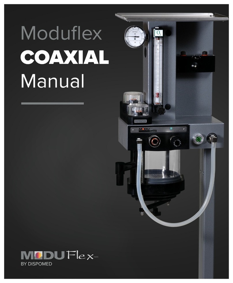
dispomed MODUFlex User manual

Printed in Canada

805-0975-030
2
TABLE
OF CONTENTS
User Responsibility ........................3
Standard Features .........................4
Receiving and Assembly Instructions .........5
Assembly On
• Moduflex Optimax....................6
• Wallmount Moduflex Optimax..........7
• Moduflex Coaxial and Elite.............8
• Moduflex Compact and Compact+ ......9
• Moduflex NRB ......................10
• Moduflex Labvet .................... 11
• Moduflex Other Anesthesia Machine ...12
Daily Leak Check Procedure................13
Consumable Materials List .................15
Warranty ................................16
Order Part Numbers ......................17

805-0975-030 3
Read this manual before operating the unit. Pay special attention to
all warnings and cautions.
• This product will perform in conformity with the description
contained in this operating manual when assembled, operated,
maintained and repaired in accordance with the instructions
provided.
• This product must be verified periodically.
• A defective product should not be used.
• Parts that are broken, missing, plainly worn, distorted or
contaminated should be replaced immediately.
• Should a repair or replacement become necessary, Dispomed
recommends that a request be placed by phone or in writing to the
nearest Dispomed regional service center.
• This product, or any of its parts, should not be repaired other than
in accordance with written instructions provided by Dispomed and
by Dispomed trained personnel.
• The product may not be altered without prior written approval
from Dispomed.
• The user of this product shall have the sole responsibility for any
malfunction which results from improper use, faulty maintenance,
improper repair, damage or alteration by anyone other than a
Dispomed trained technician.
USER
RESPONSIBILITY

805-0975-030
4
STANDARD FEATURES
• Integrated gas evacuation valve with a momentory push feature for a rapid transfer
between spontaneous and controlled ventilation.
• Integrated gas evacuation exhaust port is built into the mounting bracket,
eliminating the risk of obstruction in the tube.
• Integrated 0.5 cm H2O check valve built into the adaptor to reduce the possibility
of a faulty evacuation system drawing out into the patient’s fresh gas supply.
• A pressure gauge offers excellent visibility of circuit pressure.
• 5 year warranty.
THE MODUFLEX
BAIN
Mounting Bracket
Evacuation Outlet
Evacuation Post
Evacuation Post
Manometer
Evacuation Valve
Breating Bag Connection
Mounting Bracket
#965-0500-000
#965-0550-000
Evacuation Outlet
Patient Circuit Connection

805-0975-030 5
Your Moduflex Bain requires some assembly
before use.
RECEIVING
In order to reduce the possibility of damage
to a minimum during shipping, certain
components have been detached from
the unit. These components are packed
separately within the shipping crate.
INSPECTION
On receipt of your unit, inspect the shipping
container and the enclosed components for
signs of damage. Check your Materials List to
ensure that all the necessary components are
included.
RECEIVING AND ASSEMBLY
INSTRUCTIONS
x2
x1
x1
x1
x1
x1
x1 x1
Or

805-0975-030
6
ASSEMBLY
ON MODUFLEX OPTIMAX
On Moduflex Optimax install the Bain circuit
adaptor as illustrated.
Connect fresh gas tube to fresh gas outlet of
anesthesia machine.
Connect bain tube to front connection
of adaptor and breathing bag to bottom
connection. Install gas evacuation tube to
bottom connection of post mount.

805-0975-030 7
On Wallmount Moduflex Optimax install the
Bain circuit adaptor as illustrated.
Connect fresh gas tube to fresh gas outlet of
anesthesia machine.
Connect bain tube to front connection
of adaptor and breathing bag to bottom
connection. Install gas evacuation tube to
bottom connection of post mount.
ASSEMBLY
ON WALLMOUNT MODUFLEX OPTIMAX

805-0975-030
8
On Moduflex Coaxial and Elite install the Bain
circuit adaptor as illustrated.
Connect fresh gas tube to fresh gas outlet of
anesthesia machine.
Connect bain tube to front connection
of adaptor and breathing bag to bottom
connection. Install gas evacuation tube to
bottom connection of post mount.
ASSEMBLY
ON MODUFLEX COAXIAL AND ELITE

805-0975-030 9
On Moduflex Compact and Compact+ install
the Bain circuit adaptor as illustrated.
Connect fresh gas tube to fresh gas outlet of
anesthesia machine.
Connect bain tube to front connection
of adaptor and breathing bag to bottom
connection. Install gas evacuation tube to
bottom connection of post mount.
ASSEMBLY
ON MODUFLEX COMPACT AND COMPACT +

805-0975-030
10
On Moduflex NRB install the Bain circuit
adaptor as illustrated.
Connect fresh gas tube to fresh gas outlet of
anesthesia machine.
Connect bain tube to front connection
of adaptor and breathing bag to bottom
connection. Install gas evacuation tube to
bottom connection of post mount.
ASSEMBLY
ON MODUFLEX NRB

805-0975-030 11
On Moduflex Labvet install Bain circuit
adaptor as illustrated.
Connect fresh gas tube to fresh gas outlet of
anesthesia machine.
Connect bain tube to front connection
of adaptor and breathing bag to bottom
connection. Install gas evacuation tube to
bottom connection of post mount.
ASSEMBLY
ON MODUFLEX LABVET

805-0975-030
12
On all other anesthesia machine install Bain
circuit adaptor as illustrated. (Requires
optional Universal Bracket #985-0025-300)
Connect bain tube to front connection
of adaptor and breathing bag to bottom
connection. Install gas evacuation tube
to bottom connection of post mount.
Connect fresh gas tube to fresh gas outlet of
anesthesia machine.
ASSEMBLY
ON OTHER ANESTHESIA MACHINE

805-0975-030
13
3
Connect the circuit to be verified to the fresh gas
outlet of the anesthesia machine.
Obstruct the patient’s circuit outlet with a plug or
your thumb.
Open the flowmeter to approximately 200 ml. Close the gas evacuation valve.
The unit’s integrity should be verified every day, and at each
replacement of patient circuit components such as breathing
bags, tubes etc. A properly maintained anesthesia machine
reduces gas consumption and operating room pollution.
Prerequisites:
Oxygen supply of 40 to 60
psi (3 bar) Breathing circuit
and bag.
DAILY LEAK
CHECK PROCEDURE
1 2
4

805-0975-030 14
If you encounter an excessive leak, it is
recommended that you proceed by elimination
to find the source of the problem by replacing a
single component at a time. The most frequent
leaks can be found at the fresh gas outlet o’ring,
the patient circuit and the bag.
Once the leak is identified, dispose of the
defective item to avoid it being reused by error.
At the end of each day, it is recommended that
you close the oxygen tank and fill the
anesthetic agent vaporizer.
DAILY LEAK
CHECK PROCEDURE
5
8
Press the oxygen flush button and hold until
the pressure on the manometer indicates
approximately 30 cm H2O.
Check the manometer. The pressure must not
drop (But it can increase). If the pressure drops,
replace the patient circuit and the bag and try
again.
Caution: Open the evacuation valve before using
the anesthesia machine again.
6
7

805-0975-030
15
CONSUMABLE MATERIALS
LIST
0.5 liter: # 940-321525
1 liter: # 940-321625
2 liters: # 940-321725
3 liters: # 940-321825
5’: # 985-0060-000
REBREATHING BAGS GAS EVACUATION TUBING
Blue : # 940-2490-60B
Green : # 940-2490-60V
BAIN CIRCUIT

805-0975-030 16
DISPOMED
WARRANTY
Dispomed Ltd. guarantees that the Moduflex
Bain is free from manufacturing defects for
a period of five (5) years from the date of
delivery to the customer, provided that it is
used according to the instructions provided
and that the prescribed maintenance and
service are performed.
Dispomed shall not be held liable for
damage, injury or loss arising out of the
use of the product, whether as a result of a
defect in the product or otherwise, if, prior
to such damage, injury or loss, the product
was:
1. Damaged, misused or misapplied;
2. Repaired, altered or modified by a
person other than a Dispomed Ltd.
technician or approved service person;
3. Not installed in strict compliance with
the instructions provided by Dispomed
or with the applicable codes and
ordinances in place;
4. Cleaned using alcohol or other
damaging products.
Plastic, rubber and consumable items are
guaranteed to be free of defects at the date
of delivery to the customer.
Any product which proves to be defective in
workmanship or material will, at Dispomed’s
discretion, either be repaired or replaced.
Dispomed Ltd. is not responsible for
deterioration, wear or abuse of this unit.
This warranty shall be void for any product
on which the serial number has been
altered, defaced or removed.
Shipping charges for any unit repaired
or replaced are the responsibility of the
customer. Loaner units are available while
your unit is being repaired.
SERVICE AND INFORMATION
CENTER
Contact us at:
T: 1-800-363-1746
T: 1 450 759-9395
F: 1 450 759-8181
Email: [email protected]
Website: www.dispomed.com
blog: www.veterinary-equipment.net
Facebook: www.facebook.com/dispomed
Twitter: twitter.com/Dispomed
Youtube: www.youtube.com/dispomedltd

805-0975-030
17
REPLACEMENT
PART NUMBERS
Evacuation Valve
985-6050-000
O-ring
845-S019
O-ring
845-S019
Check Valve
965-0500-015
O-ring
845-S017
O-ring
845-S020
Manometer
900-6050-000

Manufactured by Dispomed ltd
745 Nazaire-Laurin Joliette (QC) Canada J6E 0L6
T : 1-800-363-1746 (Canada and U.S.A only)
T : 1-450-759-9395
Fax : 1-450-759-8181
www.dispomed.com
PRINTED IN CANADA
Other manuals for MODUFlex
1
Table of contents
Other dispomed Medical Equipment manuals

