dispomed MODUFlex COAXIAL User manual


805-0975-025
2DISPOMED Ltd. / 1 800 363-1746 / [email protected] / www.dispomed.com
TM/MC
TABLE
OF CONTENTS
User Responsibility .......................... 3
Standard and Optional Features ............... 4
Receiving , Assembly and Instructions .........5-9
Assembled View ............................10
Optional accessories Assembly Instructions ...11-14
Assembled View With Optional Accessories .....15
Daily Leak Check Procedure ............... 16-17
Moduflex Elite ..............................18
Annual Maintenance.........................19
Consumable Materials List...................20
Warranty...................................21
Order Part Numbers ..................... 22-23
ModuflexTM is a trademark of Dispomed Ltd.

805-0975-025 3
TM/MC
Read this manual before operating the unit. Pay special attention to all
warnings and cautions.
• This product will perform in conformity with the description
contained in this operating manual when assembled,
operated, maintained and repaired in accordance with the
instructions provided.
• This product must be verified periodically.
• A defective product should not be used.
• Parts that are broken, missing, plainly worn, distorted or
contaminated should be replaced immediately.
• Should a repair or replacement become necessary, Dispomed
recommends placing a request by phone or in writing to the
nearest Dispomed regional service center.
• This product, or any of its parts, should not be repaired other
than in accordance with written instructions provided by
Dispomed and by Dispomed trained personnel.
• The product may not be altered without prior written approval
from Dispomed.
• The user of this product shall have the sole responsibility
for any malfunction which results from improper use, faulty
maintenance, improper repairs, damage or alteration by
anyone other than a Dispomed trained technician.
USER
RESPONSIBILITY

805-0975-025
4DISPOMED Ltd. / 1 800 363-1746 / [email protected] / www.dispomed.com
TM/MC
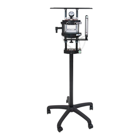
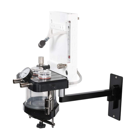
The Moduflex Coaxial is the first machine to incorporate a CO2 absorber with an integrated Coaxial
breathing circuit. This reduces clutter, eliminates the possibility of a disconnection, and reduces heat
loss by preheating the inhaled gasses with the exhaled gasses. The Moduflex Elite is the same as the
Moduflex Coaxial, but with the traditional “Y” connections.
STANDARD FEATURES
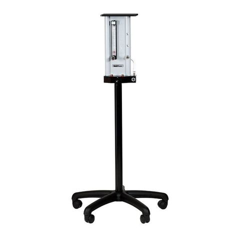
• 0.1 to 4 LPM O2 flowmeters (up to 2 flowmeters
can be installed).
• Rotary float and large scale for easy readability.
• Recessed flush valves to prevent accidental
activation.
• Quick connect fresh gas outlet for easy and
secure switching between breathing circuits.
• SELECTATECTM compatibility manifold for easy
and quick installation of vaporizer
• 1500 ml CO2 absorber with integrated coaxial
breathing circuit reduces patient heat loss, helps
to humidify the inspired gas and reduce clutter.
• Condensation trap to prevent water build-up in
soda lime. Easy and efficient gas sealing.
• Momentary closed features incorporated into
pop-off valve.
• Convenient anesthesia monitor shelf.
• 2.5 meter oxygen supply hose (D.I.S.S.).
• 5-year warranty.
OPTIONAL FEATURES
• Small cylinder holder
• Bain circuit adaptor
• 0-1 LPM O2 flowmeter
• Up to 2 flowmeters can
be installed
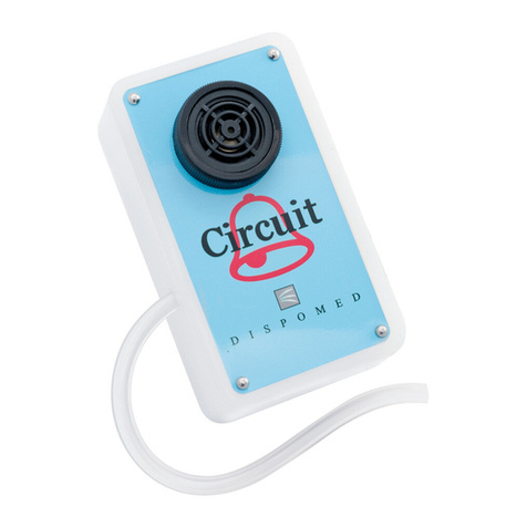
• Circuit pressure alarm
• Extra large monitor shelf
THE COAXIAL
ANESTHESIA MACHINE

805-0975-025 5
TM/MC
Your Moduflex Coaxial or Elite anesthesia ma-
chine requires some assembly before use. The
Moduflex Elite is the same as the Moduflex
Coaxial, but with the traditional “Y” connec-
tions.
RECEIVING
In order to reduce the possibility of damage to
a minimum during shipping, the head assembly
and other breathing circuit components have
been detached from the unit. These compo-
nents are packed separately within the ship-
ping crate.
INSPECTION
On receipt of your unit, inspect the shipping
container and the enclosed components for
signs of damage. Check your Materials List to
ensure that all the necessary components are
included.
RECEIVING AND ASSEMBLY
INSTRUCTIONS
x1
x1
x1
x1 x1 x1
x1
x1 x1
OR
x4
x1
OR
x1 x1
x1
Coaxial Elite
Coaxial Patient Circuit
Y Patient Circuit for Elite unit
x1

805-0975-025
6DISPOMED Ltd. / 1 800 363-1746 / [email protected] / www.dispomed.com
TM/MC
Carefully remove the head assembly from the
box (caution: do not use the shelf assembly as
a carrying handle, damage to the shelf may oc-
cur) and slide the U-channel onto the post of the
base assembly (the absorber connections face
the same way as the locking castors).
RECEIVING, ASSEMBLY
INSTRUCTIONS CONTINUED
Remove the base assembly from the box and
place it upright on the floor with locking castors
at the front and slide the post onto the base with
threaded holes positioned as illustrated.
21

805-0975-025 7
TM/MC
Insert and tighten the four levelling screws at
the top and the bottom of the post.
Remove the accessories from the bag.
RECEIVING, ASSEMBLY
INSTRUCTIONS CONTINUED
3 4

805-0975-025
8DISPOMED Ltd. / 1 800 363-1746 / [email protected] / www.dispomed.com
TM/MC
Install the breathing tube to the CO2 absorber
connection with a small twisting motion.
When connecting a Universal F circuit
(not included) pay attention to the inspiration
and expiration outlets to hook them up
correctly.
5a. Install the oxygen supply tubing to the oxy-
gen supply inlet at the back of the machine. 5b.
Connect the other end of the oxygen tube to a
50 p.s.i. (3 bars) oxygen supply.
Inspiration
Expiration
Universal F
Breathing Circuit
SKU: 940-12U6006
RECEIVING, ASSEMBLY
INSTRUCTIONS CONTINUED
5a
5b
6 Coaxial
6 Elite
Inspiration
Expiration
a
b

805-0975-025 9
TM/MC
Connect the fresh gas hose from the fresh gas
outlet to the CO2 fresh gas inlet.
CAUTION: Always depress locking mechanism
while inserting and removing fresh gas connec-
tion.
Install the breathing bag on the swivel bag
mount.
RECEIVING, ASSEMBLY
INSTRUCTIONS CONTINUED
7 8

805-0975-025
10 DISPOMED Ltd. / 1 800 363-1746 / [email protected] / www.dispomed.com
TM/MC
Install the gas evacuation tube to the back of the
machine.
1. Loosen the absorber sealing screw and re-
move the soda lime canister. 2. Affix Soda Lime
expiration label to the Soda Lime container. 3.
Fill the canister with absorbent using loose-fill
granules. (Caution: do not overfill the canister;
leave approximately ¼” (5 mm) from the top
empty.) 4. Reinstall the canister and tighten the
sealing screw.
RECEIVING, ASSEMBLY
INSTRUCTIONS CONTINUED
9 10
1
2

805-0975-025 11
TM/MC
1500 ml CO2
Absorber Canister
Flowmeter
Flush valve
Vaporiser Manifold
ASSEMBLED
VIEW 1

805-0975-025
12 DISPOMED Ltd. / 1 800 363-1746 / [email protected] / www.dispomed.com
TM/MC
OPTIONAL ACCESSORIES
ASSEMBLY INSTRUCTIONS
BAIN CIRCUIT ADAPTOR
VAPORIZER
1
1
2
2
1. Insert the vaporizer into the bracket. 2. Secure
the vaporizer in place with the locking mecha-
nism.
1. Screw the Bain adapter holder onto the anes-
thesia machine. 2. Insert the Bain adapter into
the bracket previously attached to the unit.
*Bain type open circuit on an anesthesia machine
gives you better control during surgery. The
breathing bag is always inflated, no need to wait
for it to have reached a certain size before venti-
lating the patient. Moduflex Bain is equipped with
a pressure gauge that gives you the possibility to
check the animal’s lung pressure. The Bain adap-
tor is equipped with a momentary valve to avoid
forgetting the valve in a closed position, which
could cause pulmonary trauma to the animal.

805-0975-025 13
TM/MC
OPTIONAL ACCESSORIES
ASSEMBLY INSTRUCTIONS
Screw the interface to anesthesia unit using the
screws provided in the package. Install the scav-
enger interface as per interface instructions.
During surgery unused gas should be evacuated
outside of the building to avoid it being inhaled
by your employees and patients. Connected to
a gas evacuation ventilator, the scavenger inter-
face controls the flow of suction and maintains
the balance with the quantity of unused gas.
CIRCUIT ALARMSCAVENGER INTERFACE
1
2
IMPORTANT: Always refer to the user manual of the
option you are installing for more detailed instruc-
tions.
1. Screw the circuit alarm holder on the anes-
thesia machine. 2. Screw the circuit alarm to the
support previously screwed to the device.
During assisted ventilation, the alarm will alert
you if the predetermined pressure level is
reached. For example, if you forget the evacua-
tion valve in a closed position, the circuit alarm
will alert you with a warning sound at the prede-
termined pressure.

805-0975-025
14 DISPOMED Ltd. / 1 800 363-1746 / [email protected] / www.dispomed.com
TM/MC
OPTIONAL ACCESSORIES
ASSEMBLY INSTRUCTIONS
IMPORTANT : Always refer to the user manual of
the option you are installing for more detailed
instructions.
1. Place and screw the two sections of the
holder around the post of the anesthesia ma-
chine. 2. Connect the hose to the appropriate
connections.
The cylinder holder can be helpful in many situ-
ations. It can be very useful when there is a lack
of oxygen in the central system. In the occasion-
al case where you need to move an anesthetized
animal to a room where there are no oxygen out-
lets, the cylinder holder enables you to keep the
patient in an ideal condition.
E-TANK HOLDER
1
2

805-0975-025 15
TM/MC
ASSEMBLED VIEW
WITH OPTIONAL ACCESSORIES
Bain Circuit Adaptor
965-0500-000
Installation on page 12
Patient Circuit Alarm
987-0010-000
Installation on page 13
Vaporizer
990-VI5P-SVEEZ
Installation on page 12
Cylinder Holder
975-0300-400
Installation on page 14
Scavenger Interface
985-0200-000
Installation on page 13

805-0975-025
16 DISPOMED Ltd. / 1 800 363-1746 / [email protected] / www.dispomed.com
TM/MC
Connect the circuit to be verified to the fresh
gas outlet of the anesthesia machine.
Obstruct the patient’s circuit outlet with a plug
or your thumb.
Open flowmeter to approximately 200 ml. Close the gas evacuation valve.
The unit’s integrity should be verified every day, and at each re-
placement of patient circuit components such as breathing bags,
tubes, etc. A properly maintained anesthesia machine reduces gas
consumption and operating room pollution.
Prerequisites:
Oxygen supply of 40 to 60 psi
(3 bars) Breathing circuit and
bag.
DAILY LEAK
CHECKS PROCEDURES
2
3 4
1

805-0975-025 17
TM/MC
If you encounter an excessive leak, it is recom-
mended that you proceed by elimination to find
the source of the problem by replacing a single
component at a time. The most frequent leaks
can be found at the fresh gas outlet o’ring, the
patient circuit and the bag.
Once the leak is identified, dispose of the de-
fective item to avoid it being reused by error.
At the end of each day, it is recommended that
you close the oxygen tank and fill the
anesthetic agent vaporizer.
8
Press oxygen flush button and hold until the
pressure on the manometer indicates approxi-
mately 30 cm H2O.
Check the manometer. The pressure must not
drop (but it can increase). If the pressure drops,
replace the patient circuit and the bag and try
again.
Caution: Open the evacuation valve before us-
ing the anesthesia machine again.
DAILY LEAK
CHECKS PROCEDURES
5 6
7

805-0975-025 18
TM/MC
ANNUAL
MAINTENANCE
845-S019 x2
845-S019 x2
845-S010 x2
845-S106 x2
845-S113 x2
845-S011 x1
845-S113 x1
980-0200-055 x2
980-0300-100 x1
980-0300-105 x1
Prerequisite:
Preventative maintenance kit
# 975-0900-900
The maintenance kit contains
all the necessary parts to per-
form the annual maintenance.
Refer to this technical draw-
ing the replacement parts are
identified. Perform the daily
leak check procedure (page
17) once after the mainte-
nance is done.
980-0300-300 x1

Moduflex Elite Only
# 940-3704-800
Y PATIENT CIRCUIT
805-0975-025
19 DISPOMED Ltd. / 1 800 363-1746 / [email protected] / www.dispomed.com
TM/MC
CONSUMABLE MATERIALS
LIST
0.5 liter: # 940-0200-005
1 liter: # 940-0200-010
2 liters: # 940-0200-020
3 liters: # 940-0200-030
Moduflex Coaxial Only
# 940-0200-200
1.6 liters: # 905-8855-000
18.9 liters: # 905-8862-000
REBREATHING BAGS
KRYTOX
COAXIAL PATIENT
CIRCUIT
GAS EVACUATION TUBING
CARBON DIOXIDE
ABSORBENT
7g : # 850-0052-000 152.4cm / 5’ :
# 985-0065-000

805-0975-025 20
TM/MC
Dispomed Ltd. guarantees that the Moduflex
Compact anesthesia machine is free from
manufacturing defects for a period of five
(5) years from the date of delivery to the
customer, provided that it is used according
to the instructions provided and that the
prescribed maintenance and service are
performed.
Dispomed shall not be held liable for
damage, injury or loss arising out of the
use of the product, whether as a result of a
defect in the product or otherwise, if, prior
to such damage, injury or loss, the product
was:
• Damaged, misused or misapplied;
• Repaired, altered or modified by a
person other than a Dispomed Ltd.
technician or approved service people;
• Not installed in strict compliance with
the instructions provided by Dispomed
or with the applicable codes and
ordinances in place;
• Cleaned using alcohol or other
damaging products.
Plastic, rubber and consumable items are
guaranteed to be free of defects at the date
of delivery to the customer.
Any product which proves to be defective in
workmanship or material will, at Dispomed’s
discretion, either be repaired or replaced.
Dispomed Ltd. is not responsible for
deterioration, wear or abuse of this unit.
This warranty shall be void for any product
on which the serial number has been
altered, defaced or removed.
Shipping charges for any unit repaired
or replaced is the responsibility of the
customer. Leaner units are available while
your unit is being repaired.
SERVICE AND INFORMATION CENTER
Dispomed Ltd is proud to offer its customers
an online or telephone service to answer
any questions or concerns regarding its
products.
Contact us at:
T: 1-800-363-1746
T: 1 450 759-9395
F: 1 450 759-8181
Email: [email protected]
Website: www.dispomed.com
Facebook: www.facebook.com/dispomed
Youtube: www.youtube.com/dispomedltd
DISPOMED
WARRANTY
Table of contents
Other dispomed Medical Equipment manuals
