NewTom VGi User manual

97070029
Rev. 4
28.10.2016
NewTom VGi –Installation Manual
EN

NOTES
This document is provided as a consultation manual intended for the device users.
CEFLA s.c.follows a policy based on the constant development and update of the product. For this reason, it
reserves the right to change the content of this manual without prior notice.
This document can not be modified, copied, reproduced, distributed, saved on magnetic or optical supports, or
published on websites and other on-line services, in full or in part, without the prior written authorisation of CEFLA
s.c.
The original version of this manual is in Italian.
NEWTOM™ VG is a trademark of CEFLA s.c.
All other products and trade names mentioned in this document are registered marks of the relevant
manufacturers.
INFORMATIVE NOTE OF THE MANUFACTURER ON THE MEDICAL DEVICES
The medical device referred to in this manual consists of a scanner and a control, display and calculation
unit (Main Workstation). Such device, as delivered and configured by the production and assistance
technical personnel, is an X-ray device compliant with the safety requirements set forth by the Italian
Legislative Decree of 19 September 1994, no. 626 implementing Directives 89/391/EEC, 89/654/EEC,
89/655/EEC, 89/656/EEC, 90/269/EEC, 90/270/EEC, 90/394/EEC and 90/679/EEC concerning the
improvement of the health and safety of workers in the workplace, and with the essential requirements set
forth by the Italian Legislative Decree 24 February 1997, no. 46 implementing Directive 93/42/EEC as
amended, on the medical devices.
The medical device referred to in this manual is an X-ray device compliant with Directive 2011/65/EU on the
restriction of the use of certain hazardous substances in electrical and electronic equipment.
Any tampering with, modification, updating or other change both of hardware1and software2of the device as
supplied and installed by the company (and in the conditions specified in the attached documentation) may
partially or totally compromise the device expected operation. This may also alter the safety features with
consequent hazard increase for patients, operators and surrounding environment.
For this reason, should the user need to modify the device, he/she must request a written authorisation by
CEFLA s.c.
Failure to comply with what is specified in this informative note will null and void the device warranty and the
civil and/or penal responsibility for any consequent damage and/or accident and/or worsening of the patient,
operator or other people health (including the surrounding environment) will be borne by the person who
tampered with the device or his/her legal representative.
1
Adding of a new memory expansion, a new hardware on the connection bus, a printer, the replacement
of the graphic display interface represents an important modification.
2
Including the operative system and the applications already installed upon medical device delivery.
Automatic updates of the operative system, changes to network connection parameters, modification
and/or addition and/or removal of interface software with hardware (device driver) and/or services (e.g.
file and printer sharing service) and/or applications represent an important modification.

TABLE OF CONTENTS
1TARGET AND APPLICATION FIELD.................................................................................................... 1-1
2UNPACKING AND MOVING THE EQUIPMENT ................................................................................... 2-1
2.1 INSPECTION AND UNPACKING INSTRUCTIONS ..................................................................................................... 2-1
2.2 DISASSEMBLING AND MOVING THE EQUIPMENT................................................................................................... 2-2
3MOUNTING THE EQUIPMENT .............................................................................................................. 3-1
4CONNECTING THE EQUIPMENT ......................................................................................................... 4-1
4.1 CONNECTING THE POWER SUPPLY............................................................................................................ 4-1
4.2 CONNECTING THE CONSOLE WORKSTATION............................................................................................... 4-1
4.3 CONNECTING THE EXTERNAL EMERGENCY BUTTON.................................................................................... 4-1
4.4 CONNECTING THE READY STATE SWITCH (OPTIONAL)................................................................................. 4-1
4.5 CONNECTING THE EXTERNAL DOOR SWITCH (OPTIONAL) ............................................................................ 4-1
5MOUNTING THE EQUIPMENT COVERS.............................................................................................. 5-1
5.1 FIXING THE DEVICE (OPTIONAL) .............................................................................................................. 5-19
5.2 TESTING THE EQUIPMENT....................................................................................................................... 5-21
5.3 CALIBRATING THE SYSTEM ..................................................................................................................... 5-21
5.4 FINISHING TOUCHES .............................................................................................................................. 5-21

NewTom VGi –Installation Manual 1-1
1 Target and Application Field
This manual provide informations and instructions regarding the unpacking, moving and installation
operations about the NewTom VGi device –option 7FOV / 3FOV (with “VGi 7FOV” and “VGi 3FOV” are
intended the NewTom VG produced from January 2011).
For more details about NewTom VGi, please refer to the “Service Manual” document.
This manual is intended for trained personnel recognized by the manufacturer of the NewTom VGi device.
Prior to operating or servicing this device, this manual must be read and understood.
Keep this and other associated manuals for future reference and for new operators or qualified service
personnel.

NewTom VGi –Installation Manual 2-1
2 Unpacking and moving the equipment
2.1 Inspection and unpacking instructions
Thoroughly inspect the exterior of the crates for damages which might have occurred during shipment.
Report any damage to delivering carrier and follow their instructions.
Each crate is equipped with a tilt watch indicator that turns from white to red if the package has tilted
during shipment. Check the indicator before opening the crates.
WARNING:
During the process of unpacking, dismounting and re-
mounting the equipment, Electro Static Discharges (ESD) may
occur.
Please refer to the “Service Manual” document for a proper
protection against ESD.
The equipment is shipped in three crates: one for the upper part of the mechanical structure, one for the
control box, the lower part of scanner unit and its accessories and one for the rotating part of scanner
unit.
Make sure that enough space is available to uncrate the equipment, and have easy access to the
installation site.

NewTom VGi –Installation Manual 2-2
WARNING:
Never try to uncrate and stand up the equipment before
unloading from the delivery truck.
Carefully open the crates number 1 and 2 (mechanical structure of the column and the control box), with
the help of a hammer and crowbar. Remove all four-side panels.
REMOVE CAREFULLY THE SIDE LOCKING WITH WOOD SCREWS OF THE THE CRATE NUMBER 3 (ROTATING
PART). REMOVE ALL THE WOOD SCREWS IN ALL FOUR-SIDE PANELS. REMOVE THE ROTATING PART OF
THE SCANNER WITH OWN WOOD SUPPORT.
REBUILD THE CRATE (IT WILL BE NECESSARY TO MOUNT THE ROTATING PART WITH THE MECHANICAL
STRUCTURE).
REMOVE THE PACKING LIST AND VERIFY THAT ALL THE LISTED ITEMS ARE INCLUDED IN THE CRATES.
Remove all the packing material and store the component boxes in a safe place. Carefully inspect all
components inside the crate for signs of any shipping or internal damage. Do not attempt set-up,
installation, or operation of any damaged system.
2.2 Disassembling and moving the equipment
Pay attention to do not scratch the coverings. Keep the screws and the washers in a safe place.
Always proceed slowly and carefully while moving the materials from the unloading area to the
installation site. Fast movements can damage both the scanner unit parts and the control box. Ensure the
access way is as clean as possible.
Pay particularly attention while negotiating doors and corners. Always verify the capacity and size of the
elevator if you plan to use one to move the equipment.
Once the equipment (scanner unit and control box) will be placed in the installation site make sure to
place
the console workstation 1.5 m away from the patient location (electrical safety regulations compliance).

NewTom VGi –Installation Manual 3-1
3 Mounting the equipment
NOTE:
To conduct installation and maintenance, the NewTom
VGi requires a minimum distance of 25 cm (10 inches)
from the rear wall and 25 cm (10 inches) from the
sidewalls.
Define the final position of the machine.
Place horizontally the upper part of the scanner unit
close to the device final position.
Fix the upper part of the scanner unit to the lower one.
Properly connect the wires from the upper part to M2
terminal.
WARNING:
Wires and terminal numbering must coincide!

NewTom VGi –Installation Manual 3-2
Fasten the earth cable from the upper part to the lower
earth bar.
Properly connect the MOLEX connectors from the upper
part to the lower ones.
WARNING:
Wires numbering must coincide!
Mount the actuator to the lower part of the scanner unit.
Fix the other end of the actuator to the upper part of the
scanner unit and mount the forelocks.

NewTom VGi –Installation Manual 3-3
After mounting the actuator, remove the block plates.
Fix through the proper screws the scanner unit base to
the lower chassis part, then screw the 8 feet under the
scanner base.
Lift the scanner unit up to a standing position.
Fix the Ethernet cable with a wrapper to the scanner unit
lower part.

NewTom VGi –Installation Manual 3-4
Place the iron plate on the lower part and fix together
the cables, the plate and the legs with two cable tie.
Place the rotating part on the crate.
Move the crate close to the machine to fixing the
rotating part to the mechanical structure using 8 M6x30
socket head screws with spring washers (4 screws on
each side).
1
2
4
3
Properly connect the MOLEX connectors (1 and 4).
WARNING:
Wires numbering must coincide!
Properly connect the wires to M3 terminal (2).
WARNING:
Wires and terminal numbering must coincide!
Fasten the earth cable (3).

NewTom VGi –Installation Manual 4-1
4 Connecting the equipment
4.1 Connecting the power supply
For connecting the power supply details refer to the “Service Manual”
4.2 Connecting the console workstation
For connecting the console workstation details refer to the “Service Manual”
4.3 Connecting the external emergency button
For connecting the external emergency details refer to the “Service Manual”
4.4 Connecting the ready state switch (optional)
For connecting the ready state switch details refer to the “Service Manual”
4.5 Connecting the external door switch (optional)
For connecting the external door switch details refer to the “Service Manual”
NewTom VGi –Installation Manual 5-1
5 Mounting the equipment covers
1. Fix the "UPPER SLIDING COVER" with 4 M6x20 socket head screws (2 screws on each side). After
that centering the laser like last paragraph.
NOTE:
In order to remove the cover, make sure to disconnect C30 connector and the black shield
(unscrew the red faston from the connectors plate)
4 M6x20 round head screws
UPPER SLIDING COVER
(99934337)ER
(99934499)
2. Fix the “SHELF COVER” with 4 M6x20 socket head screws.
2 M6x20 round head screws
SHELF COVER
(99934499)
2 M6x20 socket head screws
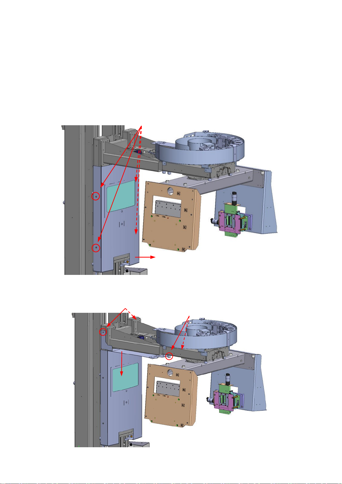
NewTom VGi –Installation Manual 5-2
3. Move the rotating arm as shown in figure.
Place the "UPPER ROTATING ARM PLATE" and fix it with 4 M6x20 socket head screws.
99934499 – 99934499 –
4 M6x20 socket head screws
UPPER ROTAT. ARM PLATE
(99934497)
4. Place the "MOBILE BELLOWS COVER" making sure that the cables are under the cover.
Fix it with 2 M6x20 socket head screws.
MOBILE BELLOWS COVER
(99934500)
2 M6x20 socket head screws

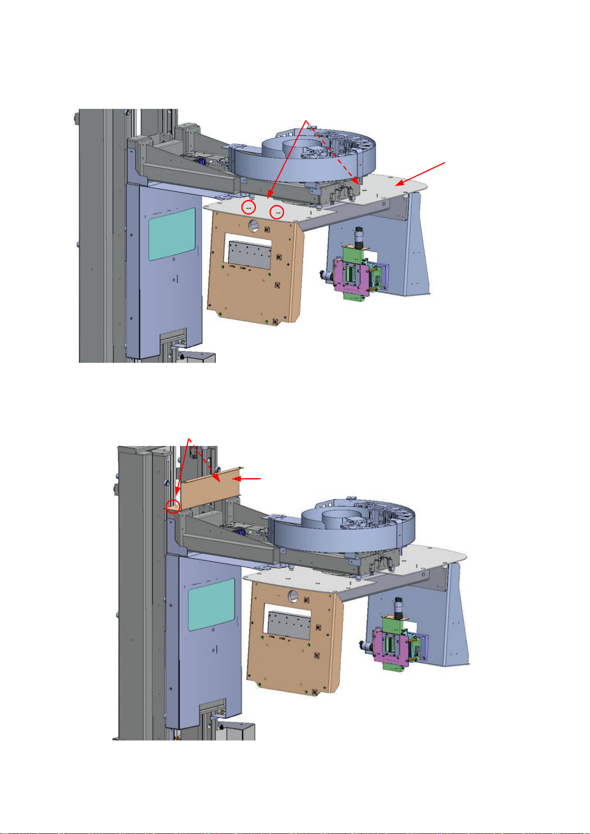
NewTom VGi –Installation Manual 5-3
(lateral sight)
5. Place the "ROUND SHELF COVER" and making sure that the upper translating cover is embedded
under the round sliding cover.
Rotate the arm until you can see the holes for the screws. Fix the cover with 4 M6x20 socket head
screws.
ROUND SHELF COVER
(99934498)
4 M6x20 socket head screws
joint
(bottom sight)
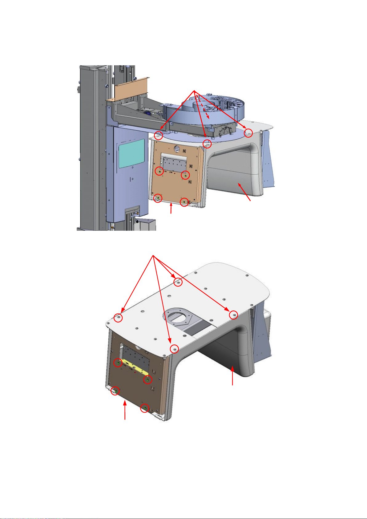
NewTom VGi –Installation Manual 5-4
6. Place the "ROTATING ARM COVER". Fix the cover with 4 M6x16 socket head screws. Use 4 M4x40
screws to fix in the center the lower rotating arm cover with the flat panel surface.
ROTATING ARM COVER
(97465020)
4 M4x40 socket head screws
4 M4x16 socket head screws
ROTATING ARM COVER
(97465020)
4 M4x16 socket head screws
4 M4x40 socket head screws
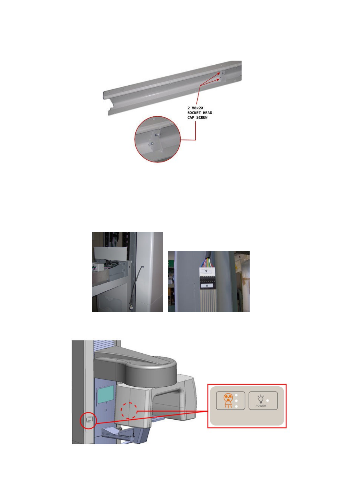
NewTom VGi –Installation Manual 5-5
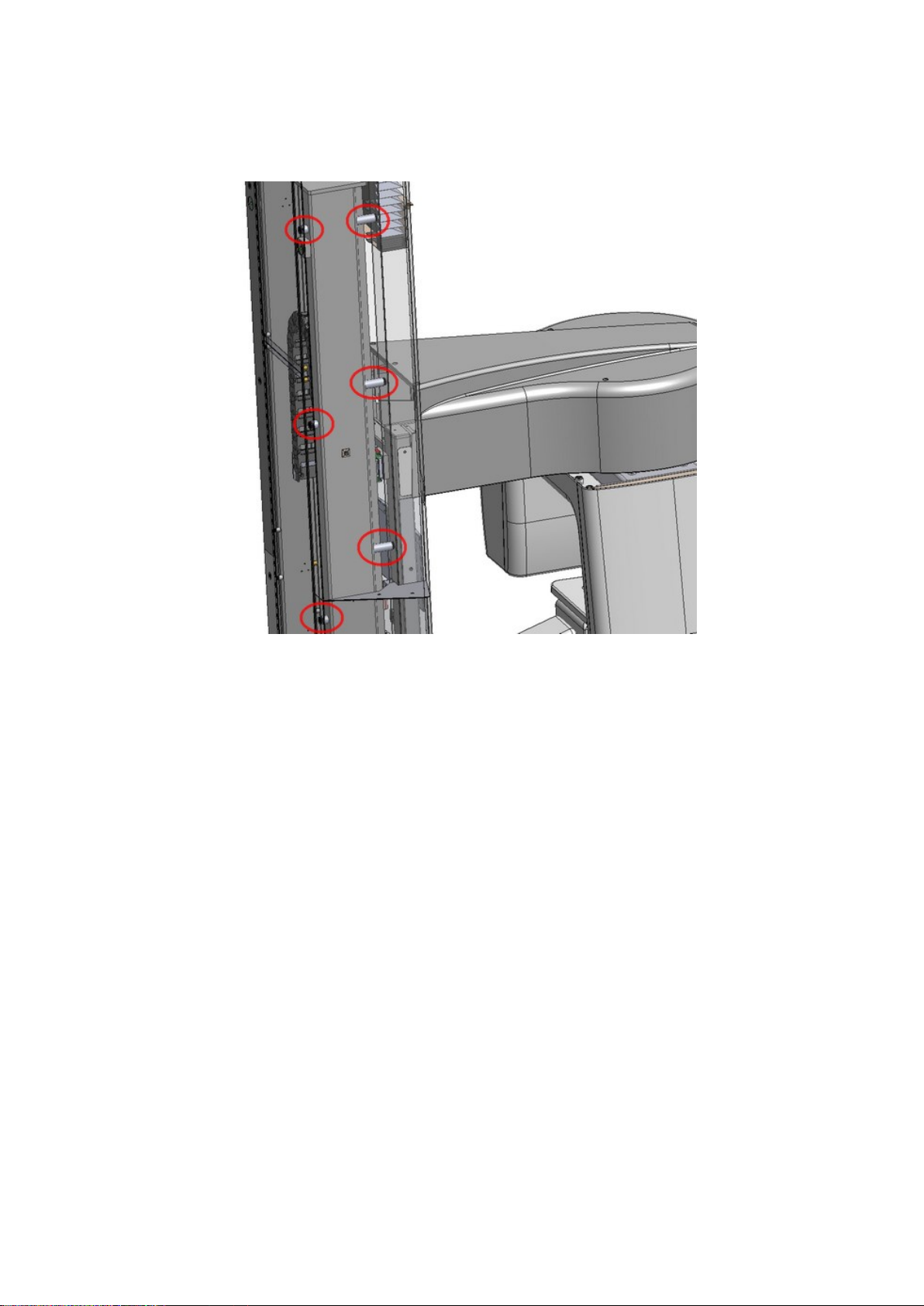
7. Connect the lower and upper parts of the "upright side coverings" (LOWER SIDE COVERS + UPPER
SIDE COVERS) and fix them together with 2 M8x20 socket head screws and 2 M8 nuts.
8. Mount the "UPRIGHT SIDE COVERINGS" on the scanner unit chassis.
WARNING:
Remember to not leave the wires inside the "upright side coverings".
Connect to the proper wires the lateral keypads (see the arrows designed on the connectors)
9. Stick on the keypads in proximity of the holes of the "UPRIGHT SIDE COVERINGS"
NewTom VGi –Installation Manual 5-6
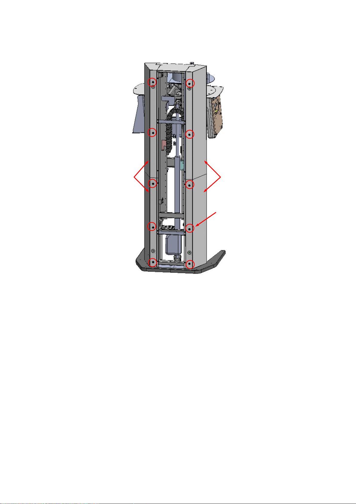
10. Mount the column spacers (10 “SHORT SPACERS” (99934522) on the back side, 8 “LONG
SPACERS” (99934521) in front)

NewTom VGi –Installation Manual 5-7
11. Fix the "upright side coverings" (LOWER RIGHT C. + UPPER RIGHT C. and LOWER LEFT C. +
UPPER LEFT C.) with 10 M6x8 roundhead cap screws (rear side) and with 8 M6x8 roundhead cap
screws (front side)
VGi Standard
10 M6x8 roundhead screws
(rear) + 8 M6x8 (front)
LOWER RIGHT SIDE +
UPPER RIGHT SIDE COVERS
(99934560 + 99934561)
LOWER LEFT SIDE +
UPPER LEFT SIDE COVERS
(99934562 + 99934563)
NewTom VGi –Installation Manual 5-8
VGi Flex
10 M6x8 roundhead screws
(rear) + 8 M6x8 (front)
LOWER RIGHT SIDE +
UPPER RIGHT SIDE FLEX
COVERS
(99934721 + 99934591)
LOWER LEFT SIDE +
UPPER LEFT SIDE FLEX
COVERS
(99934722 + 99934592)

NewTom VGi –Installation Manual 5-9
12. Mount the “LONGITUDINAL COVER (97465044)”and the “VERTICAL COVER (97465045)”on the
motorized head support by pushing the ball studs into the plastic couplings and fix the covers with
2 M4x10 roundhead screws
BALL STUDS
13. Fix 2 “HANDLE BARS (99934570)”on the bottom side of the head support with 4 M4x16 flathead
screws
Other manuals for VGi
1
Table of contents
Other NewTom Medical Equipment manuals


Popular Medical Equipment manuals by other brands


PremierOne
PremierOne MUV-403H Installation & maintenance instructions

ACS
ACS A1040 MIRA Operation manual

PARCUS MEDICAL
PARCUS MEDICAL SLiK Directions for use

North-Vision Tech
North-Vision Tech Deluxe-80 user manual

Ossur
Ossur PRO-FLEX XC PXC0xyyz Instructions for use

Timago
Timago TGO-E BM-R 610 Instructions for use


