manuals.online logo
Brands
  1. Home
  2. •
  3. Brands
  4. •
  5. Distech Controls
  6. •
  7. Controllers
  8. •
  9. Distech Controls EC-NPB-2X-485 Manual

Distech Controls EC-NPB-2X-485 Manual

EC-NPB-2X-485 Option
HARDWARE INSTALLATION GUIDE
EC-NPB-2X-485 Option
05DI-HI2X485-13 Updated:September2014 1
This document covers the mounting and wiring of the
EC-NPB-2X-485 option card in a Distech Controls
EC-BOSAX controller, including EC-BOS-2/3/6AX,
EC-BOS-7AX, or EC-BOSAXSecurity series.
Refer to the appropriate EC-BOSAX hardware
installation document for further installation details.
Included in this Package
Included in this package find the following items:
• EC-NPB-2X-485 option card, connector end plate,
and (if recent model) four 2-pin jumper blocks.
• Two 3-position terminal plugs, for wiring to an
RS-485 network.
• This EC-NPB-2X-485 Option Hardware Installation
Guide, 05DI-HI2X485-13.
Material and Tools Required
The following may be required for installation:
• #2 Phillips screwdriver: used to install the card.
• Small flat-blade screwdriver: used for making
wiring connections to the RS-485 networks.
Figure 1 EC-NPB-2X-485 option.
Preparation
Examine the component side of the option card to see
if bias resistor jumper pins are available. See Figure 2.
If so, you may wish to enable biasing for either (or
both) RS-485 ports before mounting the card—you
cannot reach these jumpers when the card is installed.
Figure 2 Jumpers to enable RS-485 bias resistors.
Note An earlier EC-NPB-2X-485 option card does
not have Bias jumpers. It operates like the
newer option card in factory-shipped state
(jumper blocks not installed—no biasing).
Installing jumpers to enable biasing adds two onboard
3.3K ohm resistors into an RS-485 port’s circuit:
• from RS-485 “+” to 5V.
Table 1 EC-NPB-2X-485 option description.
Description Notes / COM Port Assignments
Dual port,
opticallyisolated
RS-485adapter,
with two
3-position,
removable
screw-terminal
connector plugs.
See Figure 3 on
page 2 for
location of
Option Slots 1
and 2 on an
EC-BOS-2/3/6AX
.
Recent option cards have jumpers for
enabling onboard bias resistors. See
“Preparation,” page 1, for more details.
Most EC-BOSAX models have two option
slots, where COM assignments are:
•EC-BOS-2/3/6AX, EC-BOSAXSecurity: If
single RS-485 option in Slot 1: COM3,
COM4.
If two RS-485 options, ports are Slot 1:
COM3, COM4 and Slot 2: COM5, COM6.
•EC-BOS-7AX: If single RS-485 option in
Slot 1: COM5, COM6.
If two RS-485 options, ports are Slot 1:
COM5, COM6 and Slot 2: COM7, COM8.
Also see “COM Port Usage,” page 3.
SR 584
s
XRXT
XRXT
s
COM3 / COM5
COM7
COM4 / COM6
COM8
See Notes in
Table 1.
Jumper pins to
enable RS-485
Bias resistors
(found on newer
cards only)
to bias
this port
to bias
this port
Screened
diagram shows
how to enable a
port’s Bias
resistors
(two jumper
blocks on the
header pins).
EC-NPB-2X-485 Option
Updated: September 2014 05DI-HI2X485-13
Mounting
Mounting
2
• from RS-485 “–” to Ground.
Biasing sometimes improves RS-485 communications
by eliminating “indeterminate” idle states.
In general, only one device on an RS-485 trunk
should be biased. Otherwise, undue loading of the
circuit may result, with fewer devices supported.
Note RS-485 bias resistors are different than
“termination resistors”, externally installed at
the two physical ends of a daisychained
RS-485 trunk, across the “+” and “–”
terminals. Termination resistors are typically
100 or 120 ohm value resistors.
Whenever termination resistors are used, RS-485
biasing is typically required.
To enable biasing, install two 2-pin jumper blocks on
that port’s jumper header, as shown in Figure 2. To
turn off biasing, remove both 2-pin jumper blocks from
that port’s header ( the factory-shipped state).
Mounting
Warning Power to the controller must be OFF when
installing or removing option cards, or
damage will occur! Also, you must be very
careful to plug any option card into its
connector properly (pins aligned).
Mount the EC-NPB-2X-485 option card in either of the
option card slots of the EC-BOSAX, as needed.
See “Preparation,” page 1 for details about RS-485
resistor biasing, available on newer option cards.
See “COM Port Usage,” page 3 for details about
EC-BOSAX COM port assignments.
Procedure 1 Mounting EC-NPB-2X-485 option card on an
EC-BOSAX.
1.
Remove power from the EC-BOSAX—see the
previous Warning. Wait for all LEDs on the unit to
be Off.
Note If accessory modules are plugged into the
EC-BOSAX, you may need to slide them away
from the unit to get to the cover tabs.
2.
If an EC-BOS-2/3/6AX series or EC-BOSAXSecurity,
remove the battery and bracket assembly by
taking out the screws holding it in place, setting
screws aside for later. See Figure 3.
Figure 3 Remove screws and battery assembly.
Note
The tie wrap on the battery pack should have
its lock “knot” on
top
, as shown in
Figure 3
.
If not, cut and
remove
the tie, then
re-install
another tie wrap with its lock tab on top.
(
Tie lock at bottom interferes with option card
).
3.
Remove the blanking end plate for the slot you are
installing the option card into.
(Retain the blanking end plate in case the option
card must be removed at a later date.)
Note Slot 2 option card installation in an
EC-BOS-7AX controller requires careful
attention! See the EC-BOS-7AX Hardware
Installation Guide for more details. This
document focuses on installation in an
EC-BOS-2/3/6AX series controller.
4.
Carefully insert the pins of the EC-NPB-2X-485
into the socket of the appropriate option card slot.
The mounting holes on the option board should
line up with the standoffs on the base board. If
they do not, the connector is not properly aligned.
Press until the option card is completely seated.
5.
Place the custom end plate that came with the
EC-NPB-2X-485 over its connector (see Figure 4).
Screws (4)
Option Slot 2
Area
EC-BOS-2/3/6AX
Blanking
End Plate
Battery
Assembly
(includes
cable and
bracket)
Unplug
battery here
Option Slot 1 Area
Tie Wrap
Lock
(see Note)
Wiring COM Port Usage
EC-NPB-2X-485 Option
05DI-HI2X485-13 Updated: September 2014 3
Figure 4 EC-NPB-2X-485 inserted, end plate on top.
6.
If unplugged, plug the battery cable back into the
battery connector on the EC-BOSAX (see Figure 4
for location on the EC-BOS-2/3/6AX).
7.
For the EC-BOS-2/3/6AX series or
EC-BOSAXSecurity, set the battery and bracket
assembly back over the option card slots, with
mounting holes aligned with the standoffs.
Screws enter holes in the battery bracket first.
Figure 5 Re-fasten screws.
8.
Place the screws through the end plate(s), and into
the standoffs on the base board. Using a
screwdriver, hand tighten screws.
9.
If accessory modules were unplugged from the
EC-BOSAX, plug them back as before, and secure.
Wiring
Connect to an RS-485 multipoint network using one of
the 3-position screw terminal connectors, using
shielded 18-22 AWG wiring. Refer to the TIA/EIA-485
standard for more details.
Screw terminals are minus (–), plus (+), and shield (S),
as indicated on the EC-NPB-2X-485 end plate
label—see Figure 1 on page 1.
LEDs
Four LEDs are visible on the top of the
EC-NPB-2X-485 option card (cover must be removed
from EC-BOSAX). The label on the EC-NPB-2X-485 end
plate notes these four LEDs as “TX” and “RX”—see
Figure 1 on page 1.
The two LEDs for each port are described as follows:
• TX (yellow) — Transmit, indicates that the
EC-BOSAX is sending data to a device connected on
the RS-485 trunk.
• RX (green) — Receive, indicates that the
EC-BOSAX is receiving data from a device
connected on the RS-485 trunk
COM Port Usage
The
EC-NPB-2X-485
option card has two onboard
UARTs, and so adds two COM ports on the installed
EC-BOSAX controller. The hosted station
automatically resolves the option’s COM addresses.
• If an
EC-BOS-2/3/6
AX
or EC-BOS
AX
Security
controller and
installed
in Option Slot 1, or if the
only
option card, ports are COM3 and COM4.
•
If an EC-BOS-7
AX
controller and installed in Option
Slot 1, or if the
only
option card, ports are COM5 and
COM6.
If installed in Slot 1 of an
EC-BOSAX
along with
another
option card that uses COM ports in Option Slot 2, note
that COM assignments for that other card are affected.
For example, if an EC-BOS-2/3/6AX with an
EC-NPB-2X-485 option installed in Slot 1, and a single
port RS-232 option installed in Slot 2, COM assignments
are: Slot 1 (RS-485): COM3, COM4, Slot 2 (RS-232):
COM5.
The same option card mix in an EC-BOS-7
AX
controller
yields: Slot 1 (RS-485): COM5, COM6, Slot 2 (RS-232):
COM7
Place custom end
plate over end of
option card.
Insert option card into
option card slot
carefully, with pins
aligned.
Fully seat card.
EC-BOSAX
Battery
Connector
EC-BOS-2/3/6AX
EC-BOS-2/3/6AX
Hand tighten the
4 screws through
battery bracket,
end plates, into
standoffs.
COM Port Usage
COM Port Usage
Information and/or specifications published here are current as of the date of publication of this document. Distech Controls, Inc. reserves the right to change or
modify specifications without prior notice. The latest product specifications can be found by contacting our corporate headquarters. Products or features contained
herein are covered by one or more U.S. or foreign patents.
Distech Controls Inc.
www.distech-controls.com 05DI-HIGPRSX-13
05DI-HIGPRSX-13

Other Distech Controls Controllers manuals
Distech Controls ECLYPSE User manual

Distech Controls

Distech Controls ECLYPSE User manual

Distech Controls ECLYPSE ECY-303 User manual

Distech Controls

Distech Controls ECLYPSE ECY-303 User manual

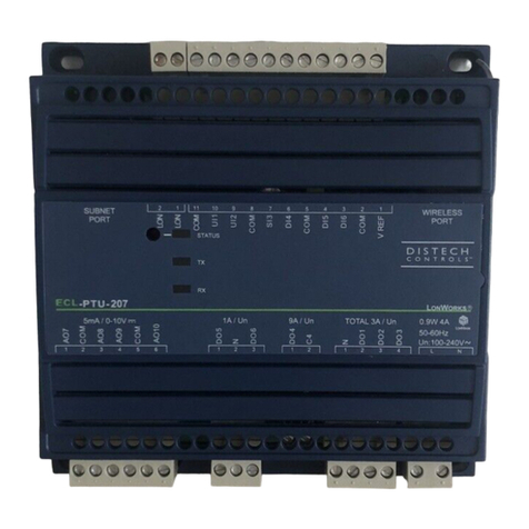
Distech Controls ECL-PTU Series User manual

Distech Controls

Distech Controls ECL-PTU Series User manual

Distech Controls VA-045PNX024P Manual

Distech Controls

Distech Controls VA-045PNX024P Manual

Distech Controls DA-016N024PX User manual

Distech Controls

Distech Controls DA-016N024PX User manual

Distech Controls ECB-VAV-N User manual

Distech Controls

Distech Controls ECB-VAV-N User manual

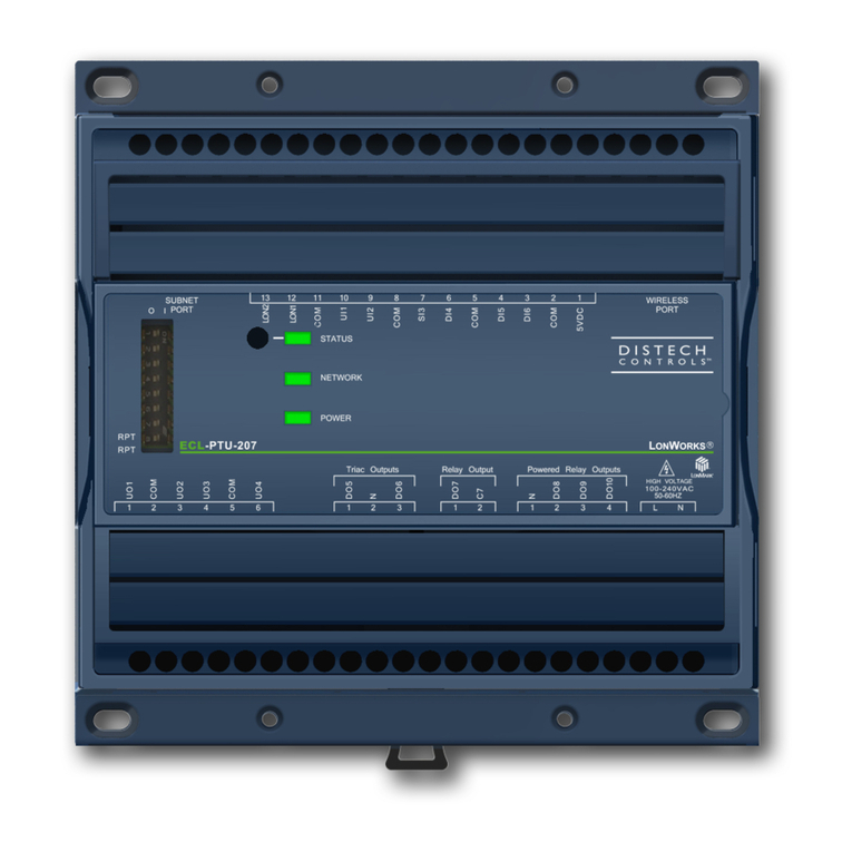
Distech Controls ECL-PTU-207 User manual

Distech Controls

Distech Controls ECL-PTU-207 User manual

Distech Controls DA-020S024PX User manual

Distech Controls

Distech Controls DA-020S024PX User manual

Distech Controls ECB-VAVS User manual

Distech Controls

Distech Controls ECB-VAVS User manual

Distech Controls DA-088N Series Manual

Distech Controls

Distech Controls DA-088N Series Manual

Distech Controls ECB-PTU Series User manual

Distech Controls

Distech Controls ECB-PTU Series User manual

Distech Controls VA-056P Series Manual

Distech Controls

Distech Controls VA-056P Series Manual

Distech Controls ECL-VAVS User manual

Distech Controls

Distech Controls ECL-VAVS User manual

Distech Controls ECLYPSE ECY-VAV User manual

Distech Controls

Distech Controls ECLYPSE ECY-VAV User manual

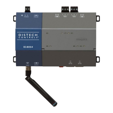
Distech Controls EC-BOS-8 User manual

Distech Controls

Distech Controls EC-BOS-8 User manual

Distech Controls DA-008S230DX User manual

Distech Controls

Distech Controls DA-008S230DX User manual

Distech Controls ECL/ECB-PTU Series User manual

Distech Controls

Distech Controls ECL/ECB-PTU Series User manual

Distech Controls DA-020S230DX User manual

Distech Controls

Distech Controls DA-020S230DX User manual

Distech Controls ECB-VAV UUKL User manual
Distech Controls

Distech Controls ECB-VAV UUKL User manual

Distech Controls VA-024ZS Series Manual

Distech Controls

Distech Controls VA-024ZS Series Manual

Distech Controls ECLYPSE User manual

Distech Controls

Distech Controls ECLYPSE User manual

Distech Controls LonMark ECL-VAV-N User manual

Distech Controls

Distech Controls LonMark ECL-VAV-N User manual

Distech Controls ECL-VAV Series Manual

Distech Controls

Distech Controls ECL-VAV Series Manual

Distech Controls ECB Series Manual

Distech Controls

Distech Controls ECB Series Manual
Popular Controllers manuals by other brands
AAON Pioneer Gold 3.0 Technical guide

AAON

AAON Pioneer Gold 3.0 Technical guide

AUMA SA 48.1 Operation instructions

AUMA

AUMA SA 48.1 Operation instructions

ABB PSE18 Installation and commissioning manual

ABB

ABB PSE18 Installation and commissioning manual

VOLTCRAFT HygroCube 100 operating instructions

VOLTCRAFT

VOLTCRAFT HygroCube 100 operating instructions

TeSuCo SOGS38 Assembly and operating manual

TeSuCo

TeSuCo SOGS38 Assembly and operating manual

SyxthSense SRC-131 user manual

SyxthSense

SyxthSense SRC-131 user manual

TAC Xenta 511 Handbook

TAC

TAC Xenta 511 Handbook

Seneca S6001 user manual

Seneca

Seneca S6001 user manual

Newlab L526MA04R2A02 user manual

Newlab

Newlab L526MA04R2A02 user manual

Barco Sedomat 1800 Specifications

Barco

Barco Sedomat 1800 Specifications

Alicat Scientific MC Series Installation & maintenance instructions

Alicat Scientific

Alicat Scientific MC Series Installation & maintenance instructions

Dynamite DYNM3860 instruction manual

Dynamite

Dynamite DYNM3860 instruction manual

GESTRA NRS 1-5b Installation and service instructions

GESTRA

GESTRA NRS 1-5b Installation and service instructions

Technische Alternative UVR610 installation instructions

Technische Alternative

Technische Alternative UVR610 installation instructions

Sentinel HID-1 instruction manual

Sentinel

Sentinel HID-1 instruction manual

Smartgen HGM1790N user manual

Smartgen

Smartgen HGM1790N user manual

ZooZ ZEN53 LR user manual

ZooZ

ZooZ ZEN53 LR user manual

Siemens QAA75 series Technical manual

Siemens

Siemens QAA75 series Technical manual

manuals.online logo
manuals.online logoBrands
  • About & Mission
  • Contact us
  • Privacy Policy
  • Terms and Conditions

Copyright 2025 Manuals.Online. All Rights Reserved.