13 / 14
Troubleshooting Guide
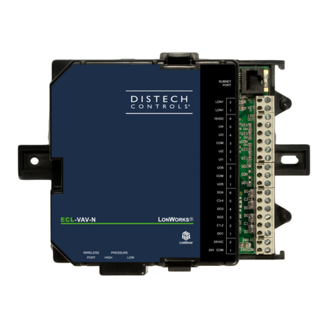
Controller is powered but does not turn on
Fuse has blown Disconnect the power. Check the fuse integrity. Reconnect the power.
Power supply polarity Verify that consistent polarity is maintained between all controllers and the transformer. Ensure that the 24VCOM terminal of
each controller is connected to the same terminal on the secondary side of the transformer. See
Power Wiring.
Controller cannot communicate on the LONWORKS network
Absent or incorrect supply voltage 1. Check power supply voltage between 24VAC ±15% and 24VCOM pins and ensure that it is within acceptable limits.
2. Check for tripped fuse or circuit breaker.
Overloaded power transformer Verify that the transformer used is powerful enough to supply all controllers.
Network not wired properly Double check that the wire connections are correct.
Absent or incorrect network termination Check the network termination(s).
Too many Allure EC-Smart-Vue Sensors are
providing network access
Disable the Net to Subnet Port Settings jumpers on all controllers (for jumper location, see Figure 9). If communications are
re-established, re-enable only a few Allure EC-Smart-Vue sensors to have network access.
Controller communicates well over a short network, but does not communicate on large network
Network length Check that the total wire length does not exceed the specifications of the
Junction Box and Wiring Guideline for Twisted Pair
LONWORKS
Networks.
Wire type Check that the wire type agrees with the specification of the
Junction Box and Wiring Guideline for Twisted Pair LONWORKS
Networks.
Network wiring problem Double check that the wire connections are correct.
Absent or incorrect network termination Check the network termination(s). Incorrect or broken termination(s) will make the communication integrity dependent upon
a controller’s position on the network.
Extra capacitance Make sure that no extra capacitance is being connected to the network other than the standard FTT circuit and a maximum
of a 3 meter stub (in bus topology).
Number of controllers on network segment
exceeded
The number of controllers on a channel should never exceed 64. Use a router or a repeater in accordance to the
Junction
Box and Wiring Guideline for Twisted Pair LONWORKS
Networks.
Network traffic Query node statistics to check for errors.
Use a LONWORKS protocol analyzer to check network traffic.
Hardware input is not reading the correct value
Input wiring problem Check that the wiring is correct according to this manual and according to the peripheral device’s manufacturer.
Configuration problem Using EC-gfxProgram, check the configuration of the input. Refer to the EC-gfxProgram user guide for more information.
Over-voltage or over-current at an input An over-voltage or over-current at one input can affect the reading of other inputs. Respect the allowed voltage / current
range limits of all inputs. Consult the appropriate datasheet for the input range limits of this controller.
Open circuit or short circuit Using a voltmeter, check the voltage on the input terminal. For example, for a digital input, a short circuit shows
approximately 0V DC and an open circuit shows approximately 3.3V DC.
Hardware output is not operating correctly
Fuse has blown (Auto reset fuse) Disconnect the power and outputs terminals. Then wait a few seconds to allow the auto-reset fuse to cool down. Check the
power supply and the output wiring. Reconnect the power.
Output wiring problem Check that the wiring is correct according to this manual and according to the peripheral device’s manufacturer.
Configuration problem Using EC-gfxProgram, check the configuration of the input. Refer to the EC-gfxProgram user guide for more information.
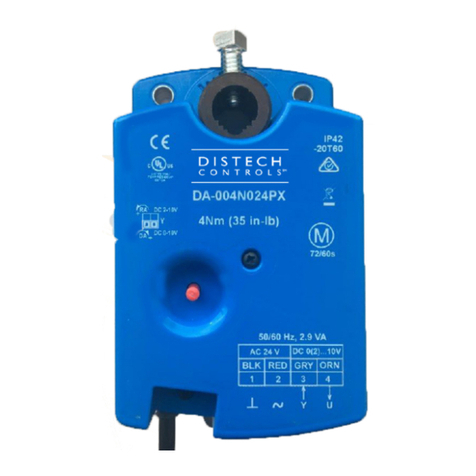
0 to 10V output, 24VAC powered actuator is not
moving.
Check the polarity of the 24VAC power supply connected to the actuator while connected to the controller. Reverse the
24VAC wire if necessary.
Wireless devices not working correctly
Device not associated to controller Using EC-
gfx
Program, check the configuration of the input. Refer to the
EC-gfxProgram user guide
for more information.
Power discharge 1. Recharge device with light (if solar-powered) or replace battery (if battery-powered),
2. Ensure sufficient light intensity (200lx for 4 hours/day).
Device too far from the Wireless Receiver Reposition the device to be within the range of the Wireless Receiver. For information on typical transmission ranges, refer
to the
Open-to-Wireless Application Guide.
Configuration problem Using the device configuration plug-in or wizard, check the configuration of the input. Refer to the Wireless Battery-less
Sensors and Switches Solutions Guide
for more information.
Flow sensor is not giving proper readings
Tubing connection problem 1. Ensure the tubing is installed properly and that the tubing is not bent.
Controller is not calibrated properly Recalibrate the controller. Refer to the controller’s user guide for more information.
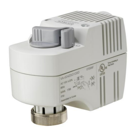
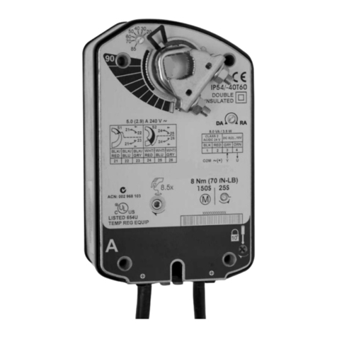
Damper is not opening or closing properly
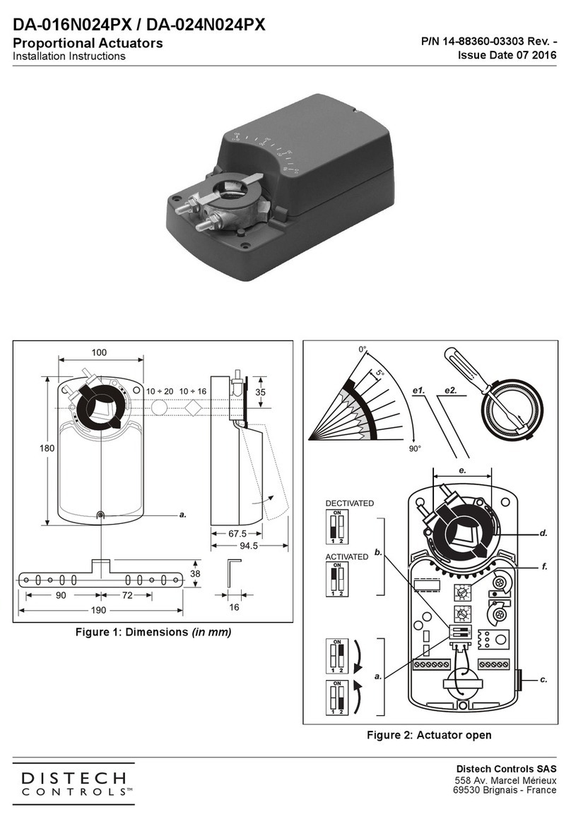
Mechanical stops not in proper position The two mechanical stops must be positioned to stop the damper motion when it is completely closed and completely
opened. The mechanical stops can be moved by increments of 5°.


