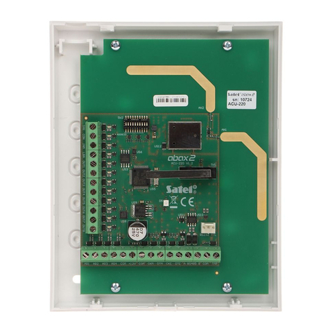
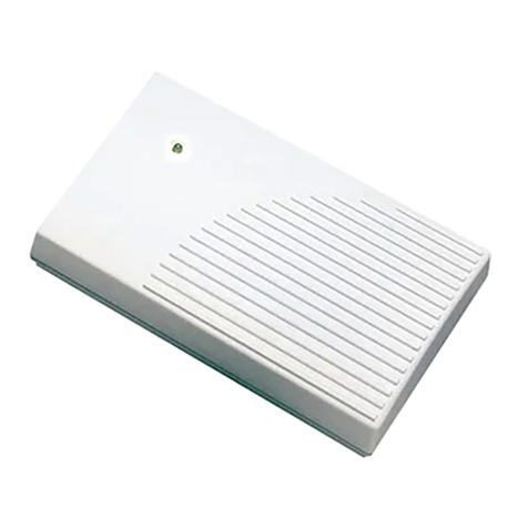
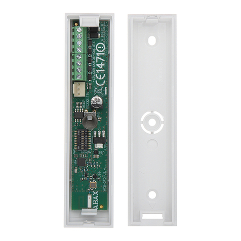
Satel Abax ACU-100 User manual

WIRELESS SYSTEM CONTROLLER
ACU-100
Program version 1.05
User Manual
acu100_e 11/06
two-way
wireless
system

IMPORTANT
The controller incorporates electronic components sensitive to electrostatic discharges. Prior
to installation, remove the electrostatic discharges and avoid touching the controller board
components in the process of installation.
Do not deform the controller antenna, as this may adversely affect the quality of radio
communication.
DECLARATION OF CONFORMITY
Product:
ACU-100 - Controller of ABAX Wireless System
Manufacturer: SATEL sp. z o.o.
ul. Schuberta 79
80-172 Gdańsk, POLAND
tel. (+48 58) 320-94-00
fax. (+48 58) 320-94-01
Product description:The ACU-100 wireless system controller designed for interaction with other elements of
the ABAX wireless system. The device operates in the 868.0MHz – 868.6MHz frequency band, and is supplied
from a 12V DC source. The controller is intended to be used in burglary and panic alarm systems and can be
connected to any type of the alarm control panel.
This product conforms to the following EU Directives:
R&TTE 1999/5/EC
This product meets requirements of the harmonized standards:
R&TTE: ETSI EN 300 220-1: v.1.3.1; ETSI EN 300 220-3: v.1.1.1;
EMC: ETSI EN 301 489-1: v.1.5.1.; EN 301 489-3: v.1.4.1
Safety: EN60950-1:2001
Notified body taking part in conformity evaluation:
Identification No.: 1471
Gdańsk, Poland 2005-07-15 Head of Test Laboratory:
MichałKonarski
The list of countries where the ACU-100 has been approved for use - please see the website www.satel.pl
The SATEL Company sets itself an objective to continually enhance quality of its products,
which can entail changes to their technical specifications and software.
Information on the introduced modifications can be found on our web site.
Please visit us at:
http://www.satel.pl

ACU-100 SATEL 1
CONTENTS
1. General..............................................................................................................................3
2. Description of ACU-100 wireless system controller...........................................................3
2.1 Electronics board........................................................................................................................ 3
2.2 Functions of DIP-switches.......................................................................................................... 5
2.3 Control inputs ............................................................................................................................. 5
2.4 Outputs....................................................................................................................................... 7
2.5 Functional outputs ...................................................................................................................... 7
3. Wireless devices interfacing with the controller .................................................................8
3.1 ACX-100 Input & output expansion module ............................................................................... 8
3.2 ACX-200 Hardwired zone & output expander ............................................................................ 8
3.3 APD-100 Wireless passive infrared detector.............................................................................. 8
3.4 AMD-100 Wireless magnetic detector with additional input ....................................................... 8
3.5 AMD-101 Wireless magnetic detector with additional independent input...................................9
3.6 ASP-105 Wireless outdoor siren ................................................................................................ 9
3.7 ASP-205 Wireless indoor siren ..................................................................................................9
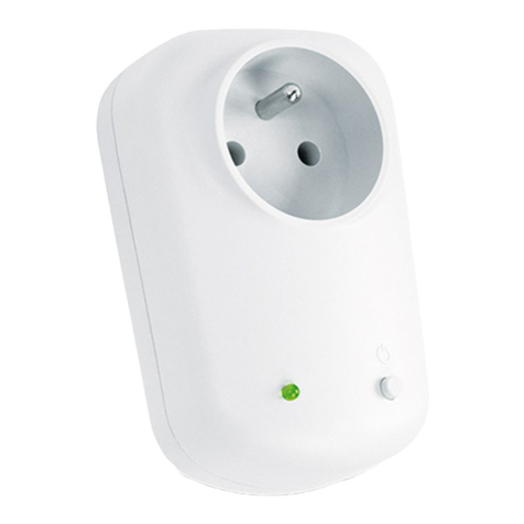
3.8 ASW-100 E 230V AC Wireless controller................................................................................... 9
3.9 ASW-100 F 230V AC Wireless controller................................................................................... 9
3.10 ARF-100 Radio signal level tester..............................................................................................9
4. Installation .......................................................................................................................10
4.1 Installation of ACU-100 wireless system controller .................................................................. 10
4.2 Connecting LCD keypad to the controller................................................................................. 10
4.3 Connecting computer to the controller ..................................................................................... 11
4.4 Connecting the ACX-100 input & output expansion modules ..................................................12
4.5 Adding new wireless devices ................................................................................................... 13
4.5.1 DLOAD10 and DLOADX programs.......................................................................................................13
4.5.2 LCD keypad connected to the controller...........................................................................................14
4.5.3 LCD keypad of INTEGRA alarm system...........................................................................................14
4.6 Removal of wireless devices .................................................................................................... 15
4.6.1 DLOAD10 and DLOADX programs.......................................................................................................15
4.6.2 LCD keypad ......................................................................................................................................15
4.7 Hardwired zone / output expander in ABAX system ............................................................... 16
4.7.1 Configuration of ACX-200 expander zones/outputs for ACU-100 controller operation with INTEGRA
control panel..................................................................................................................................................16
4.7.2 Configuration of ACX-200 expander zones/outputs for ACU-100 controller operation with CA-64
control panel..................................................................................................................................................17
4.7.3 Configuration of ACX-200 expander zones/outputs for ACU-100 controller operation with other
control panels................................................................................................................................................17
4.8 Wireless detectors in ABAX system ......................................................................................... 18
4.8.1 Installation of APD-100 detectors .....................................................................................................18
4.8.2 Installation of AMD-100, AMD-101 detectors....................................................................................19
4.9 Wireless signaling devices in ABAX system ............................................................................19
4.9.1 Installation of ASP-105 sirens...........................................................................................................19
4.9.2 Installation of ASP-205 sirens...........................................................................................................20
4.10 ASW-100 230V AC wireless controllers in ABAX system ........................................................ 22
4.11 Radio signal level tester in ABAX system ................................................................................23
5. Interaction with alarm control panels ...............................................................................24
5.1 Expander of wireless devices for INTEGRA series control panels........................................... 24
5.2 Addressable zone expander for CA-64 control panel............................................................... 27
5.3 Zone expander for CA-10 control panel ................................................................................... 28
5.4 Wireless device module interfacing with any alarm control panel ............................................ 30
6. Programming and diagnostics .........................................................................................31
Two-way wireless system ABAX ACU-1002
6.1 LCD keypad of INTEGRA security system............................................................................... 32
6.2 DloadX program....................................................................................................................... 32
6.3 LCD keypad connected to controller........................................................................................ 34
6.3.1 Service mode of keypad connected to the controller ....................................................................... 34
6.4 Dload10 program ..................................................................................................................... 35
6.5 Description of functions, options and commands .................................................................... 38
7. Restoring controller default settings.................................................................................40
8. Technical data .................................................................................................................41
9. History of the manual updates .........................................................................................42

1. GENERAL
The ACU-100 controller allows communication between any alarm control panel and the
ABAX system wireless devices. It enables wire-operated security systems to be expanded by
addition of wireless devices. The ABAX system is based on two-way communication. All
messages sent by the devices are acknowledged, which ensures that the equipment status
information will reach the controller and allows online check of the devices for their presence
in the system. Configuration of parameters and testing of the wireless devices is performed
by radio, without the need to dismantle their housings. Coded communication between the
units takes place within the frequency band of 868.0MHz – 868.6MHz.
2. DESCRIPTION OF ACU-100 WIRELESS SYSTEM CONTROLLER
The ACU-100 controller supervises and coordinates operation of up to 48 wireless devices.
The status of devices is signaled on the OC type outputs. It can also be transmitted to the
control panel through the communication bus.
The controller settings and wireless equipment parameters are programmed by means of an
LCD keypad or a PC computer.
2.1 ELECTRONICS BOARD
Fig. 1. Schematic view of ACU-100 controller PCB.
Description of terminals:
COM - common (ground)
+12V - power supply input
TMP - controller tamper terminals (NC)
ITMP - input for connecting controller tamper circuit
TPR - information output - tampers
connector socket fo
r
LCD keypad
output status LEDs
tamper contact
DIP-switches
screen buzze
r
port RS-232
antenna
operating status LED

Two-way wireless system ABAX ACU-1004
CON - information output - no radio communication with wireless device
JAM - information output - radio jamming
LBA - information output - problems with wireless device power supply
OUT1…OUT8 - information output - wireless equipment status
AR1…AR4 - control inputs
A RS485 B - RS-485 port terminals (not used)
CLK, DAT - communication bus
The tamper contact reacts to of the controller housing being opened. You can use the TMP
terminals in two ways:
•connect the terminals to the tamper circuit of the control panel;
•connect one of the TMP terminals to the ITMP tamper circuit input, and the other to the
COM ground terminal – information of the controller tamper will be fed to the TPR output
and to the communication bus.
Note: If the TMP terminals are not connected to the controller tamper circuit, the ITMP
terminal must be shorted to the common ground.
The package of DIP-switches on the board is used to set individual addresses of the
devices and to configure some working parameters of the controller (see FUNCTIONS OF DIP-
SWITCHES).
The LED indicates the controller status. The mode of lighting depends on the controller
working configuration:
•interaction with CA-64 or INTEGRA alarm control panels:
−green steady light – no communication with the control panel;
−green blinking light – correct communication with the control panel.
•interaction with other alarm control panels:
−green steady light – normal operation of the controller;
−green blinking light – synchronization in the process;
−alternate green and red blinking light – occurrence of one of the problems signaled on
functional outputs (see: FUNCTIONAL OUTPUTS).
The buzzer informs of occurrence of one of the problems signaled on functional outputs (it
does not apply to the controller interfacing with the INTEGRA series alarm control panels).
The RS-232 port with optoisolation enables a PC computer with DLOAD10 program to be
connected for the time of programming.
The RJ-11 socket is used to connect an LCD keypad for the time of programming. The
controller interfaces with LCD keypads for operating the CA-64 or INTEGRA series control
panels.
Notes:
•The controller cannot be simultaneously programmed by means of computer and LCD
keypad.
•When working with the INTEGRA alarm control panels, the controller can be programmed
by means of the control panel, with no need for connecting the keypad or computer to the
controller sockets.
The communication bus (CLK, DAT) of the controller enables direct connection to the
control panel communication bus (INTEGRA, CA-64, CA-10) or expansion of the system by
adding the ACX-100 input/output expansion modules.

ACU-100 SATEL 5
2.2 FUNCTIONS OF DIP-SWITCHES
DIP-switch number
Controller function 1 2 3 4 5 6 7 8
Wireless device module for all control panels I1I
2I
3x P 0 0 0
Expander for CA-10 with 1 keypad (6 zones) A B C D P 1 0 0
Expander for CA-10 with 2 keypads (4 zones) A B C D P 0 1 0
Expander for CA-10 with 3 keypads– (2 zones) A B C D P 1 1 0
Addressable zone expander for CA-64 A1A2A3A4A
5P 0 1
Wireless device expander for INTEGRA control panels A1A2A3A4A
5x 1 1
Table 1. The way of using DIP-switches for controller configuration.
0– DIP-switch in OFF position
1– DIP-switch in ON position
P– selection of controller programming mode:
−DIP-switch in OFF position – through RS-232 port (DLOAD10 program)
−DIP-switch in ON position – by means of LCD keypad
I1, I2, I3– DIP-switches for setting the number of ACX-100 modules connected to the
computer. To determine this number, tot up the values set on individual DIP-switches as
per Table 2.
DIP-switch number 1 2 3
Numerical value
(for switch in ON position) 1 2 4
Table 2.
The controller accepts up to 5 input/output expansion modules, hence if a higher value
is set on the DIP-switches, it will be also recognized as 5.
A, B, C, D– DIP-switches for setting the controller address in the same way as with the CA-
10 zone expanders. When in the ON position, the switch value is 1.
A1, A2, A3, A4, A5- DIP-switches for setting the controller address. In order to determine the
controller address, add up the values set on individual DIP-switches as per Table 3.
DIP-switch number 1 2 3 4 5
Numerical value
(for switch in ON position) 1 2 4 8 16
Table 3.
x- unused DIP-switch
2.3 CONTROL INPUTS
The ACU-100 PCB incorporates 4 control inputs. These inputs make it possible to control
operation of wireless equipment (detectors, sirens). How the device will respond to activation
of the input (shorting to common ground / opening connection) depends on the type of the
device controlled by the input (e.g. the detectors will change to active status, the sirens will
trigger alarm signal, the 230V AC wireless controllers will turn on electrical equipment
connected to their sockets, etc.). The control inputs are disabled when the controller operates
with the INTEGRA control panels.
The controller inputs can be programmed as NO (normally open) or NC (normally shorted to
ground).

Two-way wireless system ABAX ACU-1006
In order to control the ACU-100 controller inputs you can use any alarm control panel outputs
(OC, high-current, low-current, relay type). Where the control is effected by means of the
high-current output of a SATEL-made control panel, it is necessary to connect a 1.1kΩ
resistor to the controller input (see Fig. 2).
Fig. 2. Example of connecting the high-current output of SATEL-made control
panel to the control input.
The control panel outputs which are to control the ACU-100 controller inputs should be
properly configured (their type, polarization, cutoff time, etc.).
To control operation of the wireless detectors, the control panel output can be programmed
e.g. as the ARM STATUS. Arming in the control panel will activate the detectors, while
disarming will deactivate them. It should be remembered that activation/deactivation of the
detectors is delayed in relation to arming/disarming (see: WIRELESS DETECTORS IN ABAX
SYSTEM).
By having programmed the exit time in the control panel, you can avoid delay in activating
the detectors in relation to arming. The output programmed as the ARM STATUS will only get
active after expiry of the exit time. However, some control panels allow you to choose
another function, which activates the output immediately after arming command is given to
the control panel. For example, the output can be programmed in the CA-10 as type 35:
POWER SUPPLY ON ARMED MODE, and in the CA-64 as type 42: POWER SUPPLY IN ARMED STATE.
The delay effect in activating the detectors as against the arming can only be avoided when
the exit time exceeds the RESPONSE PERIOD.
The control input of the controller can also be programmed as always active. When this
option is chosen, the detectors will remain permanently in active state.
Wireless system controller
ACU-100
Alarm control panel
CA-64
1,1kΩ
OUT4 – reversed polarization (0V
when active)
AR1 - NO type

ACU-100 SATEL 7
In order to control the operation of sirens, you should connect the control panel alarm
signaling output to the controller input. Activating the control panel output will trigger the
siren.
You can increase the number of inputs by adding the ACX-100 expansion modules to the
controller. The maximum number of inputs can be 24 (controller + 5 ACX-100 modules). The
number of inputs can only be increased when the controller does not connect to the control
panel by means of communication bus.
2.4 OUTPUTS
The PCB of the ACU-100 controller incorporates eight OC type outputs, to which wireless
devices are assigned (by default, each newly added device is assigned to output 1). Any
number of wireless devices can be assigned to one output. The output activates after
receiving suitable information from a wireless device assigned to it, the information
depending on the device type:
•the wireless detectors signal violations;
•the ASP-105 siren inform of a discharged battery and a failure of +12V DC external power
supply.
•the ASP-205 sirens inform of battery discharge;
•the ACX-200 expanders signal zone violation;
•the ASW-100 E and ASW-100 F controllers inform that the button was depressed in Mode
0 or the electric circuit was closed in Mode 1 and 2.
The outputs can be programmed as NO (normally open) or NC (normally shorted to ground).
All the outputs (of the controller and the ACX-100 modules connected to it) are being
programmed at the same time. Depending on how the outputs have been programmed,
activation of the output is indicated as follows:
−LED assigned to the output comes ON (outputs programmed as the NO type);
−LED assigned to the output comes OFF (outputs programmed as the NC type).
The outputs can be connected to the control panel zones. It does not apply to controllers
configured for operation with the CA-64 / INTEGRA alarm control panels.
The number of outputs can be increased by connecting the ACX-100 expansion modules to
the controller. The maximum number of outputs 48 (controller + 5 ACX-100 modules). The
number of outputs can only be increased when the controller does not connect to the control
panel by means of communication bus.
2.5 FUNCTIONAL OUTPUTS
The ACU-100 controller PCB incorporates four OC type outputs to signal:
TPR - wireless device tampers, lack of communication with ACX-100 modules, and also
controller tampers (provided the TMP terminals are connected to the controller
tamper circuit);
CON - lack of communication with wireless devices;
JAM - jamming the radio signal for the ABAX system to the degree which makes
communication impossible;
LBA - problems with power supply of a wireless device: low battery, discharged storage
battery, or loss of external power supply.
Depending on how the outputs have been programmed (see OUTPUTS), activation of the
functional output is indicated as follows:
−LED assigned to the output comes ON (outputs programmed as the NO type);
−LED assigned to the output comes OFF (outputs programmed as the NC type).

Two-way wireless system ABAX ACU-1008
The functional outputs may be connected to suitably programmed zones of the control panel
(zone type, way of reaction, etc.). Thus the control panel will inform of any problem indicated
by the controller functional output. Having obtained information on the occurrence of
a problem, it can be thoroughly diagnosed by means of an LCD keypad or a computer
connected to the controller.
If the controller operates in conjunction with the CA-64 control panel, connecting the TPR
output is unnecessary, because information on tampers of wireless devices is transmitted
through the communication bus.
Where the controller operates together with the INTEGRA series alarm control panels, the
functional outputs need not be connected. In this configuration all problem-related information
is sent to the control panel through the communication bus.
3. WIRELESS DEVICES INTERFACING WITH THE CONTROLLER
3.1 ACX-100 INPUT &OUTPUT EXPANSION MODULE
•4 control inputs
•8 outputs, OC type
•communication bus
•tamper contact
•power supply: direct voltage 12V (±15%)
3.2 ACX-200 HARDWIRED ZONE &OUTPUT EXPANDER
•4 zones
•4 relay outputs
•tamper contact
•power supply: direct voltage 12V (±15%)
3.3 APD-100 WIRELESS PASSIVE INFRARED DETECTOR
•digitally processed signal from pyroelement
•high resistance to interference
•adjustable detection sensitivity
•remote configuration of parameters
•changeable Fresnel lenses
•tamper contact
•power supply: lithium battery, CR123A 3V
3.4 AMD-100 WIRELESS MAGNETIC DETECTOR WITH ADDITIONAL INPUT
•two reed switches
•input to connect any outdoor detector of NC type
•remote configuration of parameters
•tamper contact
•power supply: lithium battery, CR123A 3V

ACU-100 SATEL 9
3.5 AMD-101 WIRELESS MAGNETIC DETECTOR WITH ADDITIONAL INDEPENDENT
INPUT
•two reed switches
•individually identifiable input to connect any outdoor detector of NC type
•remote configuration of parameters
•tamper contact
•power supply: lithium battery, CR123A 3V
3.6 ASP-105 WIRELESS OUTDOOR SIREN
•optical and acoustic signaling, triggered independently by radio
•acoustic signaling: piezoelectric transducer
•remote configuration of acoustic signaling (selection of one of four acoustic signals and
duration of signaling)
•optical signaling: xenon (flash) lamp
•tamper contact
•power supply: direct voltage 12V (±15%)
•emergency power supply: 6V 1.2Ah battery
3.7 ASP-205 WIRELESS INDOOR SIREN
•acoustic signaling: piezoelectric transducer
•optical signaling: LED indicators
•remote configuration of 2 signaling modes (acoustic signaling duration, switching acoustic
signaling ON / OFF, selecting one of 3 sound signals, switching optical signaling ON /
OFF)
•tamper contact
•power supply: lithium battery CR123A 3V
3.8 ASW-100 E230V AC WIRELESS CONTROLLER
•remote switch ON / switch OFF of devices to be connected to 230V sockets
•type of controller socket: E
•button for manual control of 230V electric circuit
•LED indicator of controller status
•power supply: 230V AC
3.9 ASW-100 F230V AC WIRELESS CONTROLLER
•remote switch ON / OFF of devices to be connected to 230V sockets
•type of controller socket: F
•button for manual control of 230V electric circuit
•LED indicator of controller status
•power supply: 230V AC
3.10 ARF-100 RADIO SIGNAL LEVEL TESTER
•checking the level of radio signal received by controller from tester, or by tester from
controller

Two-way wireless system ABAX ACU-10010
•simulating radio communication of devices to be supplied from battery or external sources
•LED indicator showing the radio signal level
•buzzer
•power supply: alkaline battery 9V 6LR61
4. INSTALLATION
The ABAX two-way wireless system should be installed so as to ensure a suitable
level of radio signal from devices working together with the controller. This will allow
the communication problems to be avoided.
All electrical connections may only be made with power supply disconnected.
Before proceeding to the system installation you should plan the arrangement of all the
devices. The installation place for the controller should be chosen so that all devices to be
supervised by it are within its range. It is recommended that the controller and the wireless
devices be mounted at a high position, which will enable a better range of radio
communication to be reached, while avoiding a risk of incidental masking of the controller
and devices by people moving around the facility.
Before permanently mounting the system components, you should check the level of signal
received by the controller from individual devices. If the signal level from a particular unit is
too low (less than 40%), a change of the device position will be necessary. At times, it is
sufficient to move the device some ten to twenty centimeters to get a significant improvement
of the signal quality. Having reached the optimal level of radio signal from all devices, you
can proceed to permanently mounting them in position.
The ABAX system radio communication has been designed so as to enable several ACU-100
controllers to work within each other's range. Synchronization with the wireless systems
already in use is always performed when the controller is switched on, and after each
operation of addition/removal of supported devices. The synchronization is performed
automatically. The number of wireless devices already working within the range of each other
depends on the RESPONSE PERIOD (see DESCRIPTION OF FUNCTIONS,OPTIONS AND COMMANDS)
and can vary from 150 to 450. The higher the response frequency, the lower the number of
devices that can work within each other's range.
4.1 INSTALLATION OF ACU-100 WIRELESS SYSTEM CONTROLLER
The ACU-100 controller should be installed indoors, in spaces with normal air humidity. Its
electronics board is mounted in the OPU-1 A plastic housing. Before fastening the controller
to the wall, make inlets/outlets in the rear wall of the housing for cables to connect the
controller to the control panel or ACX-100 expansion modules.
Caution:The cables should not be laid in the close vicinity of the antenna, as this may cause
radio communication interference.
If the controller is not used together with the INTEGRA series control panels, it requires the
LCD or computer to be connected for registration of the wireless devices and software. Such
connections are temporary, for the time of programming or diagnostics.
4.2 CONNECTING LCD KEYPAD TO THE CONTROLLER
If the ACU-100 controller is to be programmed by means of LCD keypad, the keypad must be
connected to the RJ-11 socket with four-wire cable. Connection of the keypad communication
bus to the RJ-11 socket is shown in Fig. 3.
Address of the keypad to be connected to the ACU-100 controller must be set as 0.

ACU-100 SATEL 11
If properly connected, the keypad will display a message, the upper line of which will include
the device name and program version info. If the TROUBLE LED goes on in the keypad, one
of the functional outputs is active. In order to start the service mode, the service code must
be entered. The service mode is indicated by lighting of the SERVICE LED.
Fig. 3. Sequence of wires in the plug connecting LCD keypad with controller.
If the a.m. message fails to appear on the display after connection, you should:
−check that the option of programming by means of LCD keypad has been selected on the
controller DIP-switches;
−check that the cables connecting the keypad with controller have been properly connected;
−check that address 0 has been set in the LCD keypad.
In order to check the keypad address and, if necessary, to change it:
1. Disconnect the +KPD keypad power supply and the data bus cables (CKM, DTM).
2. Short the CKM, DTM keypad terminals.
3. Connect the keypad power supply.
4. The keypad address will be displayed:
Fig. 4. Programming the keypad address
5. Change the address to 0, if necessary. The keypad will acknowledge performance of the
function with four short and one long beeps.
6. Connect the keypad to the ACU-100 controller as required (CKM, DTM).
4.3 CONNECTING COMPUTER TO THE CONTROLLER
If the ACU-100 controller is to be programmed by means of a computer, the computer must
be connected to the RS-232 port.
Notes:
•Do not short or touch the RS-232 port with your fingers.
view of plug in
the socket
view of plug from
the pins side
n=0...7, current address of the keypad

Two-way wireless system ABAX ACU-10012
•Prior to connecting the cable, remove preliminarily the electrostatic charge, e.g. by
touching a grounded piece of equipment (faucet, heater, etc.) with top of your palm.
•It is recommended that the cable be first connected to the controller port.
Fig. 5. Connection of computer to the controller serial port.
If the DLOAD10 program fails to communicate with the computer after connection of the RS-
232 port, you should:
−check that the option of programming by means of RS-232 port has been selected on the
controller DIP-switches;
−check that the port through which the computer communicates with the controller has been
properly selected in the DLOAD10 program;
−check that the cables connecting the computer with controller have been properly
connected.
4.4 CONNECTING THE ACX-100 INPUT &OUTPUT EXPANSION MODULES
The ACU-100 controller communication bus can accept up to five ACX-100 input & output
expansion modules. The modules can only be connected when the controller is
configured as a wireless device module interfacing with any alarm control panel.
The ACX-100 expansion modules should be connected to the controller bus in parallel. The
connection can be made with a typical unscreened cable, as used in the security systems
(e.g. DY8x0,5). When connecting the modules, remember to set the correct number of ACX-
100 modules connected to the controller on the controller DIP-switches. Lack of
communication with the module will be signaled on the TPR output as tamper.
Each module connected to the bus must have a different address set from the range 0 to 4.
These addresses must correspond to the number of a next module, as shown in Table 4. If
one ACX-100 module is connected to the controller, it must have address 0 set, if two, one of
them must have address 0 set, and the other address 1, etc.
The numeration of control inputs and outputs of the expansion module in the system depends
on the address set in it, i.e. on the module number. The numbers of control inputs and
outputs in consecutive expansion modules are shown in Table 4.
TO CONTROLLER
(view of connector
on controller board)
2
4
5
RS-232 serial port
DTR comp.
CTS comp.
TXD comp.
RXD comp.
GND
DSR contr.
RTS contr.
RXD contr.
TXD contr.
COM
20
7
3
DB-9
DB-25
TO COMPUTER
5
2
38
(female connectors as
seen from soldering
points side)

ACU-100 SATEL 13
Consecutive module number Module address Control input numbers Output numbers
1 0 5-8 9-16
2 1 9-12 17-24
3 2 13-16 25-32
4 3 17-20 33-40
5 4 21-24 41-48
Table 4.
Fig. 6. Example of connecting two ACX-100 modules to ACU-100 controller.
The module TMP terminals must be connected to the control panel tamper circuit.
4.5 ADDING NEW WIRELESS DEVICES
4.5.1 DLOAD10 and DLOADXprograms
In order to add a new wireless device to the system, do the following:
1. Press the NEW DEVICE button in the program.
2. A window will appear, in which you should enter the 7-digit serial number of the device
being added. The serial number can be found on the electronics board or on the housing.
Each ARF-100 tester has the serial number 0000500.
3. Depending on which device is to be added to the system:
−turn on power supply of the ACX-200 expander – immediately after start-up (power-up),
the expander will send a single signal to enable registration,
Wireless system controller
ACU-100
First expansion module
ACX-100
address 0
Second expansion module
ACX-100
address 1
module
power supply

Two-way wireless system ABAX ACU-10014
−turn on the ARF-100 tester – immediately after start-up, the tester will send a single
signal to enable registration,
−plug the ASW-100 E / ASW-100 F wireless controller into the 230V socket –
immediately after being plugged into the socket, the controller will send a single signal
to enable registration,
−violate (open) the tamper contact in case of the other devices.
If an invalid serial number has been entered, you will be informed of it by a suitable
message. Then you should enter the correct serial number and repeat the above
mentioned step.
4. A confirmation message will be displayed that a new device has been added. Click your
mouse on the „OK” button to finish the procedure of new device addition. You can cancel
addition of the new device by pressing the „Abort” button. You can also add a next
wireless device by pressing the „Next” button.
Note: If the ACU-100 controller is configured for operation as the expander with the CA-64 or
INTEGRA control panels, the procedure of adding new wireless devices to the system
must be followed by the procedure of expander identification in the control panel.
4.5.2 LCD keypad connected to the controller
In order to add a new wireless device to the system, do the following:
1. Start the NEW DEVICE function.
2. Enter the 7-digit serial number of the device to be added and press the [#] key. The serial
number can be found on the electronics board or on the housing. Each radio signal level
tester has the serial number 0000500.
3. Depending on which device is to be added to the system:
−turn on power supply of the ACX-200 expander – immediately after start-up (power-up),
the expander will send a single signal to enable registration,
−turn on the ARF-100 tester – immediately after start-up, the tester will send a single
signal to enable registration,
−plug the ASW-100 E / ASW-100 F wireless controller into the 230V socket –
immediately after being plugged into the socket, the controller will send a single signal
to enable registration,
−violate (open) the tamper contact in case of the other devices.
If the entered serial number is different from that of the device being added, or a device
with this number has already been registered, a message with suitable information will be
displayed, followed by the automatic return to the main menu.
4. A message will confirm addition of the new device with the serial number shown on the
display. Press the [#] key to finish the procedure of adding the new device. You can
cancel the new device addition by pressing the [*] key.
4.5.3 LCD keypad of INTEGRA alarm system
In order to add a new wireless device to the system, do the following:
1. Start the function NEW DEVICE (ÆSERVICE MODE ÆSTRUCTURE ÆHARDWARE ÆEXPANDERS
ÆSETTINGS Æcontroller name ÆNEW DEVICE)
2. Enter the 7-digit serial number of the device and press the [#] key. The serial number can
be found on the electronics board or on the housing. Each radio signal level tester has the
serial number 0000500.
If a device with the entered serial number is already registered in the system, the keypad
will signal it by 3 long beeps and will fail to proceed to the next step of the procedure.

ACU-100 SATEL 15
3. After the „Open device tamper” is displayed:
−turn on power supply of the ACX-200 expander – immediately after start-up (power-up),
the expander will send a single signal to enable registration,
−turn on the ARF-100 tester – immediately after start-up, the tester will send a single
signal to enable registration,
−plug the ASW-100 E / ASW-100 F wireless controller into the 230V socket –
immediately after being plugged into the socket, the controller will send a single signal
to enable registration,
−violate (open) the tamper contact in case of the other devices.
If the serial number of the device to be added is different from the one previously entered,
a suitable information message will be displayed. Press the [*] key and then start the
procedure of device addition from the beginning.
4. The new device name and serial number will be displayed. Press the key 1 to proceed to
the next step of the procedure (press any other key to terminate the procedure of adding
a new device).
5. A list of system zones which can be assigned to the device will be displayed. Select one
of them (use the Tand Skeys to scroll the list) and press the [#] key (press the [*] key
to terminate the procedure of new device addition). If the device takes up more than one
zone in the system (e.g. AMD-101 magnetic detector, ASP-105 siren, or ACX-200
expander), additional zones will be automatically assigned to it (subsequent in order to
the indicated one). The zone(s) will be given a name consisting of the device name and
serial number. If the device takes up outputs in the system, they will be given a name
consisting of the name and serial number of the device, too.
6. Automatic identification of the expanders will be carried out (and a suitable information
message will be displayed).
4.6 REMOVAL OF WIRELESS DEVICES
4.6.1 DLOAD10 and DLOADXprograms
In order to remove a wireless device from the system by means of the LCD keypad you
should:
1. Start the REMOVE DEVICE function.
2. Select from the list the device to be removed from the system and press [#].
3. Following the displayed instruction, press the key with digit 1, to remove the device.
Removal of the device will be acknowledged by the keypad with four short and one long
beeps.
Note: Pressing any key instead of the key [1] will take you back to the selection list of
wireless devices.
4.6.2 LCD keypad
In order to remove a wireless device from the system by means of the DLOAD10 or DLOADX
programs do the following:
1. Click on the device you want to be removed.
2. Press the "Remove device" button.
3. Following the displayed instruction, press the "Yes" button to confirm your intention to
remove the device. The device will be removed.
Note: If the ACU-100 controller is configured for operation of the expander with CA-64 or
INTEGRA control panels, a new identification of expanders must be carried out after
completion of the procedure of removal of a new wireless device from the system.

Two-way wireless system ABAX ACU-10016
4.7 HARDWIRED ZONE /OUTPUT EXPANDER IN ABAX SYSTEM
The ACX-200 expander takes up 4 positions on the list of devices supported by the
controller. Up to 12 ACX-200 expanders can work together with the ACU-100 controller. The
expander sends to the controller information on the status of zones and receives commands
to change the status of relay outputs. The transmission of zone status information as well as
the output control are performed in real time mode. Only the information on expander zone
settings is sent during the response period. When polling, the controller will send information
to the expander, regarding configuration of one zone. This means that 4 response periods
are needed to send information on the settings of 4 zones. Consequently, even more than 2
minutes can elapse from the moment the new settings are programmed to the moment they
are actually saved in the expander (if the response period is 36 seconds). The settings of
expander zones are stored in non-volatile memory, hence the loss of power supply will not
mean any loss of preprogrammed settings.
Note: If the communication with the ACU-100 controller is lost, all of the previously activated
outputs will enter the inactive state after 20 response periods.
In order to install the ACX-200 hardwired zone/output expander in the system, do as follows:
1. Open the housing.
2. Make cable inlets in the rear panel of the housing for power cables / cables connecting the
expander with hardwired devices.
3. Prepare a temporary source of 12V DC power supply and add the ACX-200 expander to
the wireless system (see: ADDING NEW WIRELESS DEVICES).
4. Select the place where the ACX-200 expander is to be installed and attach it there
temporarily. It is recommended that the expander be installed as high as possible. Thus
a better radio communication range can be obtained and the risk of the expander being
accidentally covered by personnel moving around the premises.
5. Check the level of signal received by the controller from the expander. Change the place
of installation, if necessary.
6. Having obtained the optimum signal level, install the expander permanently.
7. Connect the tamper contact to one of the expander zones. Program this zone as the
tamper zone. You can also connect the tamper contact in series with a 2EOL configured
device (detector), connected to one of the expander zones.
8. Connect wire devices to the expander zones/outputs.
Note: The cables (for power supply, connection between the expander and hardwired
devices, etc.) should not be run in the immediate vicinity of the antenna, since it may
cause radio interference.
9. Configure the expander zones as required.
4.7.1 Configuration of ACX-200 expander zones/outputs for ACU-100 controller
operation with INTEGRA control panel
The ACX-200 expander occupies 4 zones and 4 outputs in the security alarm system.
Parameters of the ACX-200 zones and outputs are to be programmed in the same way as
those of the other hardwired zones and outputs of the control panel. However, it should be
borne in mind that the actual sensitivity of the ACX-200 zones may be different from that
programmed by means of the keypad or DLOADX program. Within the range of 20ms to
140ms it will precisely correspond to the programmed value. Above 140ms, only some
sensitivity values are available in the expander (300ms, 500ms, 700ms, etc., in 200ms
increments). The values above 140ms, programmed by means of the LCD keypad or the
DLOADX program, are rounded to the nearest value supported by the expander zones.

ACU-100 SATEL 17
4.7.2 Configuration of ACX-200 expander zones/outputs for ACU-100 controller
operation with CA-64 control panel
The ACX-200 expander occupies 4 zones in the alarm system. Parameters of the ACX-200
zones are to be programmed in the same way as those of the other hardwired zones of the
control panel. The DLOAD64 program or the alarm system keypad can be used for this
purpose. You must take into account the same limitations regarding the zone sensitivity as in
case of the ACX-200 expander working together with the INTEGRA control panel.
In order to configure the ACX-200 expander outputs, indicate the corresponding ACU-100
control inputs, which will control the expander outputs. It can be done by means of the LCD
keypad connected to the controller, or through the DLOAD10 program. The control inputs
should be connected to the suitably programmed outputs of the control panel.
4.7.3 Configuration of ACX-200 expander zones/outputs for ACU-100 controller
operation with other control panels
Programming the zones/outputs of the ACX-200 expander is possible by using the keypad
connected to the controller or by means of the DLOAD10 program.
It is necessary that operating configuration of the detector connected to the expander be
determined and sensitivity defined for each expander zone. Additionally, the ACX-200
expander zones should be assigned to the selected controller outputs. Irrespective of how
the ACX-200 expander zones will be programmed, the control panel zones to which the
ACU-100 controller outputs will be connected, are to be configured as NO type (see also
section INTERACTION WITH ALARM CONTROL PANELS).
In the LCD keypad, any changes of the zone type and sensitivity level are to be done by
means of the CONFIGURATION function. The Sand Tkeys make it possible to change the
parameter values. The Wand Xkeys allow you to move between the top and bottom lines of
the display, i.e. between the parameters to be programmed.
In the DLOAD10 program, click in the „Configuration” column on the field referring to the
expander zone for which type and sensitivity are to be programmed. These parameters are
separated by a dash. The first position indicates the zone type. Using the keypad, you can
enter here a digit from the 0 to 5 range, according to Table 5.
Digit Zone type
0 no detector
1 NC
2 NO
3 EOL
4 2EOL/NO
5 2EOL/NC
Table 5.
The second position indicates the zone sensitivity. Using the keypad you can enter a value
from the 20ms to 5100ms range. Within the range of 20ms to 140ms, it is possible to enter
values every 20ms (20ms, 40ms, 60ms, etc.). The next value that can be entered is 300ms.
Within the range of 300ms to 5100ms, you can enter values every 200ms (300ms, 500ms,
700ms, etc.). If a number different from the above values is entered, it will be rounded up to
the next supported value (e.g. after entering 301, the next value to be entered is 500ms).
In order to configure the ACX-200 expander outputs, indicate the appropriate ACU-100
control inputs which will control the expander outputs. The control inputs are to be connected
to the suitably programmed outputs of the alarm control panel.

Two-way wireless system ABAX ACU-10018
4.8 WIRELESS DETECTORS IN ABAX SYSTEM
The wireless detectors send information on violations, tampers, and battery status to the
ACU-100 controller. The detectors may be in either passive state (the system is disarmed)
or in active state (the system is armed). When in the passive state (battery-saving mode),
the detectors mainly communicate with the controller in time intervals determined by the
RESPONSE PERIOD option. Then the information on violations and battery status is sent. Only
the detector tamper messages are sent immediately. When in the active state, both the
violations and tampers are sent to the controller right away.
The detectors are switched over from the passive state to the active state, and vice versa,
during the response time, hence performance of this operation is delayed in relation to the
moment of switchover command. This delay, depending on the chosen response frequency,
can be up to 12, 24 or 36 seconds.
The RESPONSE PERIOD has an effect on the detector energy consumption level. The battery
use by the detector decreases as the frequency of communication between the controller and
the wireless device lowers.
It is advisable in some situations that the detector be always active. For example, the user
wants to be sure that no window is open in the facility at the moment of arming. Switching
over the window protection magnetic detector permanently in active state allows to avoid the
risk that the window will be opened just before arming, but the information about it has not yet
come.
The manner of permanently switching the detector to its active state depends on the
controller working configuration. If the controller operates together with the INTEGRA series
control panels, select the corresponding option for wireless detector. Otherwise, the controller
input for detector control should be programmed as always active.
The batteries ensure operation of the detectors for a period of about 2 years, provided
that they remain in the passive state for some portion of that period, and the RESPONSE
PERIOD is 12 seconds. The lifetime of batteries in the detectors which are permanently
switched to the active state will be reduced. On the other hand, decreasing the
response frequency will extend the battery life. For example, the battery in magnetic
detector for window protection will be sufficient for a period longer than specified, even
if it has been permanently switched over to the active state, if the RESPONSE PERIOD is
set at 36 seconds. The number of possible violations of this detector will be lower than
the number of extra transmissions with the response time of 12 seconds.
Do not leave batteries inside the detectors which are not installed in the system.
If there is no communication with the controller for 10 minutes, the detector will enter
the sampling mode. When in this mode, the detector will check for 38 seconds if it is
being polled by the controller. If it fails to establish communication with the controller, it
will enter the sleep mode for 20 minutes, and then it will check again for 38 seconds if
it is being polled by the controller, etc.
4.8.1 Installation of APD-100 detectors
In order to install the APD-100 passive infrared detector in the system you should:
1. Install battery in the detector.
2. Add the detector to the system (see: ADDING NEW WIRELESS DEVICES).
3. Select the location where you want the detector installed, and mount it temporarily in
position.
4. Check the level of signal received by the controller from the detector, and change the
detector installation place, if necessary.
5. Having reached the optimal signal level, install the detector permanently.
Table of contents
Other Satel Controllers manuals

Satel
Satel RX1K User manual

Satel
Satel MICRA VERSA-MCU User manual

Satel
Satel KNX-BSA12L User manual

Satel
Satel ACU-280 User manual

Satel
Satel ACU-120 User manual

Satel
Satel MTX-300 User manual

Satel
Satel ACU-220 User manual

Satel
Satel RX-2K User manual

Satel
Satel INT-CR User manual

Satel
Satel KNX-DIM21 User manual

Satel
Satel ACU-250 User guide

Satel
Satel RXH-1K User manual

Satel
Satel ABAX 2 ACU-220 User manual

Satel
Satel ABAX 2 ACU-280 User manual

Satel
Satel ACU-280 User manual

Satel
Satel ABAX 2 ACU-280 User manual

Satel
Satel ACU-270 User manual

Satel
Satel KNX-SA41 User manual

Satel
Satel VERSA-MCU User manual

Satel
Satel KNX-BSA12H User manual