manuals.online logo
Brands
  1. Home
  2. •
  3. Brands
  4. •
  5. Festo
  6. •
  7. Controllers
  8. •
  9. Festo VPPI D Series User manual

Festo VPPI D Series User manual

Translation of the original instructions
© 2020 all rights reserved to Festo SE & Co. KG
1 Applicable Documents
Document Product Contents
Description Proportional-pressure regulator VPPI-...-D Assembly, Installation, Oper-
ating, Parameterisation
Tab. 1
All available documents for the product èwww.festo.com/pk.
2 Safety
2.1 Safety Instructions
– Only use the product in original status without unauthorised modifications.
– Only use the product if it is in perfect technical condition.
– Take into consideration the ambient conditions at the location of use.
– Prior to mounting, installation and maintenance work: Switch off power sup-
ply and secure it from being switched back on.
– Before changing any settings in the menu of the proportional-pressure regu-
lator, read the description of the product è 1 Applicable Documents.
2.2 Intended Use
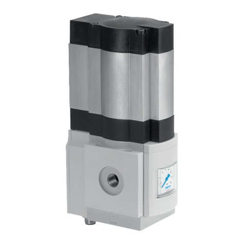
The proportional-pressure regulator is intended to regulate a pressure propor-
tional to a specified setpoint value.
The device is intended for use in an industrial environment. Outside of industrial
environments,e.g. in commercial and mixed-residential areas, actions to sup-
press interference may have to be taken.
2.3 Training of skilled personnel
Installation, commissioning, maintenance and disassembly should only be con-
ducted by qualified personnel.
The specialized personnel must be familiar with the installation and operation of
electrical and pneumatic control systems.
3 Additional Information
– Accessories èwww.festo.com/catalogue.
4 Service
Contact your regional Festo contact person if you have technical questions
èwww.festo.com.
5 Product overview
5.1 Function
A built-in pressure sensor records the pressure at the working port and compares
this value with the setpoint value. In the event of deviations between the setpoint
value and actual value, the valve regulates until the outlet pressure has reached
the setpoint value.
VPPI -...- 3 -...
(normally closed)
VPPI -...- 4 -...
(normally open)
Tab. 2 Pneumatic Circuit Symbol
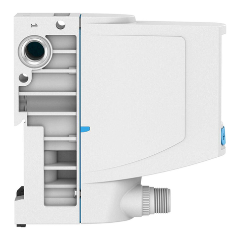
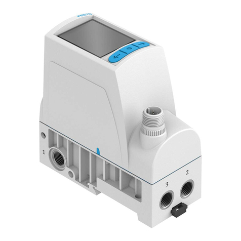
5.2 Product Design
1Display
2Operating buttons Display menu
3M12 plug
4Working air port (2)
5Exhaust air port (3)
6Compressed air port (1)
Fig. 1 Product Design
6 Transport and Storage
– Store the product in a dry, UV- and corrosion-protected environment.
– Ensure short storage times.
7 Mounting
7.1 Assembly
7.1.1 Linking of Valves
Up to 5 valves can be linked. The connecting kit VAME-P18-K-P5 is required for
linking èwww.festo.com/catalogue.
The connecting kit consists of 2 square nuts, 2 socket head screws and an O-ring.
1. Remove the plug screw and sealing material from the duct (1).
2. Insert the O-ring into the duct (1) between 2 valves è Fig.2.
Fig. 2 Insert O-ring
3. Connect the valves on the underside using socket head screws and square
nuts. Tightening torque: 1.2±0.2Nm è Fig.3
Fig. 3 Fitting for valve underside
4. Connect valves at the rear using socket head screws and square nuts. Tight-
ening torque: 1.2±0.2Nm è Fig.4
8116335
VPPI-...-D
Proportional-pressure regulator
8116335
2019-12
[8116337]
Instructions|Assembly, Installation, Operating
Festo SE & Co. KG
Ruiter Straße 82
73734 Esslingen
Germany
+49 711 347-0
www.festo.com
Fig. 4 Fitting, valve rear side
7.1.2 Creating Pressure Zones
In the case of pressure zone separation, connect the compressed air supply to
both ends of the valve manifold.
For pressure zone separation, the plug screw can be left in duct (1) of the valve.
Plug screws for duct (1) can also be ordered as accessories (VAME-P18-BP-
G18-P5) èwww.festo.com/catalogue.
1. Screw the plug screw into the duct (1) of the selected valve è Fig.5. Screw in
the plug screw until it is flush with the surrounding surface.
Fig. 5 Plug screw
2. Link valves.
7.2 Mounting
7.2.1 Mounting via Underside of Valve
Fig. 6 Mounting via underside of valve with M4 screws/M4 screws and square
nuts
7.2.2 Mounting via Side Surface
Fig. 7 Mounting via side surface with internal screws M4 / through screws M4
7.2.3 Mounting of Linked Valves
Fig. 8 Mounting of linked valves with lateral screws M4
7.2.4 Mounting on H-rail
Fig. 9 Individual valve
Fig. 10 Linked valves
7.3 Mechanical Installation
1. Make sure there is sufficient space for the connecting cable and tubing con-
nections.
ÄThis will prevent kinks from forming in the connecting cables and the
tubing.
2. Place the valve as close to the consumer as possible.
ÄThis leads to improved control precision and shorter response times.
8 Installation
8.1 Pneumatic Installation
Valves for Standard Operation (Overpressure)
1. Attach the tubing to the connections:
– Compressed air (1)
– Working air (2)
2. Fit a silencer at the exhaust air connection (3) or provide for ducted exhaust
air.
Valves for Vacuum Operation and Combined Vacuum / Overpressure Operation
(VPPI -...- 1V... H -...)
1. Attach the tubing to the connections:
– Vacuum (3)
– Working air (2)
2. Connect a compressed air supply to port (1) or mount a silencer to protect the
valve from coarse dirt particles.
8.2 Electrical Installation
WARNING!
Risk of injury due to electric shock.
• For the electric power supply, use SELV or PELV circuits that guarantee a reli-
able electric disconnection from the mains network.
• Observe IEC60204-1/EN60204-1.
1. If a screened cable is used: earth the shield at the cable end farther away
from the valve.
2. Install electrical connecting cable without squeezing, kinking or stretching.
3. Tighten the electrical connecting cable onto plug M12. Tightening torque:
maximum 0.3Nm
AllocationConnection Pin
Analogue Alternative
(digital input)
Wire colour1)
(NEBU-M12...)
1 + 24 VDC + 24 VDC BN
2 Setpoint value (-) DI1 WH
3 GND GND BU
4 Setpoint value
(+)/PWM
DI0 BK
5 Actual value output
– related to pin 2
"Setpoint value
(-)" for type
VPPI -...- V1 -...
– related to pin 3
"GND" for
VPPI -...- A4 -...
DI2 GY
1) Colour code in accordance with IEC 60757:1983-01
Tab. 3 Pin Allocation for Plug M12, 5-pin
9 Commissioning
Requirements:
– The valve must be assembled.
– The pneumatic and electrical installation must be complete and checked.
1. Check operating conditions and critical limits è 14 Technical Data.
2. Switch on the power supply.
3. Switch on the compressed air supply.
4. If necessary, adjust the control response of the valve.
Setting the Control Response
The control response of the valve can be set in the menu of the TFT screen with
the help of the operating buttons on the top of the valve èDescription propor-
tional control valve VPPI -...- D èwww.festo.com/sp.
10 Cleaning
1. Switch off the following energy sources to clean the outside:
– Compressed air
– Operating voltage
2. Clean the outside of the product with a soft cloth. Do not use aggressive
cleaning agents.
11 Malfunctions
11.1 Diagnostics
The following table shows an overview of the error messages in the display.
Error text in the display Error description Remedy
"Overheat" Working temperature is too
high. Valve is in temperature
shut-off.
Switch off the valve, let it cool
down and restart. Reduce ambi-
ent temperature or temperature
of medium.
"Cable break" Cable break setpoint input Check connection to setpoint
generator.
Replace supply cable.
"Oscillation" Continuous vibration detected. Select another parameter set
for application.
"No air supply" No input pressure p1.
Setpoint value not reached.
Increase input pressure p1.
Maintain permissible maximum
operating pressure
è 14 Technical Data.
"DC-supply low" Supply voltage is too low. Increase supply voltage.
"DC-supply high" Supply voltage is too high. Reduce supply voltage.
"Heat protection" Temperature critical, power
reduction active
Reduce ambient temperature or
temperature of medium. Ensure
sufficient compressed air sup-
ply.
"High deviation" Setpoint value not reached.
Input pressure p1 is too low.
Air consumption at the working
port is too high.
Increase input pressure p1.
Maintain permissible maximum
operating pressure
è 14 Technical Data.
"Setpoint high" Analogue setpoint value is too
high.
Correct setpoint value.
Tab. 4
11.2 Fault Clearance
Error description Cause Remedy
Operating voltage not applied. Check the operating voltage
connection.
No setpoint voltage. Check the controller and con-
nection.
Valve does not respond.
Working temperature is too
high. Valve is in temperature
shut-off.
Switch off the valve, let it cool
down and restart.
Reduce ambient temperature
and / or temperature of medi-
um.
Valve normally open:
The working pressure at (2)
falls to the level at (3) (ambient
pressure or vacuum).
Cable break setpoint input Check connection to setpoint
generator.
Replace supply cable.
Valve normally closed:
The working pressure at (2)
deviates upwards or down-
wards from the setpoint value
(working pressure is neither
pressurised nor exhausted).
Cable break setpoint input Check connection to setpoint
generator.
Replace supply cable.
Setpoint value not reached. Input pressure at (1) is too low. Increase input pressure at (1).
Maintain permissible maximum
operating pressure
è 14 Technical Data.
Tab. 5 Fault Clearance
12 Disassembly
1. Switch off compressed air supply.
2. Specify setpoint value 0bar.
3. Switch off operating voltage.
4. Remove electrical connecting cables.
5. Remove compressed air lines.
6. Dismantle the product.
13 Disposal
ENVIRONMENT!
Send the packaging and product for environmentally sound recycling in accord-
ance with the current regulations èwww.festo.com/sp.
14 Technical Data
General Technical Data
Valve function 3-way proportional-pressure regulator
Mounting position Any
Product weight [g] 370
RCMApprovals
KC
Materials
Seals HNBR
Housing PA-reinforced
Tab. 6 General Technical Data
Operating and Ambient Conditions
Ambient temperature [°C] 0…50
Storage temperature [°C] –20…+70
Temperature of medium [°C] 0…50
Degree of protection IP65
Compressed air to ISO 8573-1:2010 [7:4:4]Operating medium
Inert gases
Note on the operating medium Lubricated operation not possible
Climate class to EN60721 3k3
Nominal insert height <3000m above sea level
Vibration resistance/shock resistance (as per IEC60068)
Note Explanation of the severity levels (SG)
è Tab. 8 Features of severity level (SL)
Individual valve fastened with screws: SG2
Individual valve on H-rail: SG1
Linking of max. 3 valves with lateral screw mounting:
SG2
Vibration (part 2-6)
Linking of max. 5 valves with lateral screw mounting:
SG1
Individual valve fastened with screws: SG2
Individual valve on H-rail: SG1
Linking of max. 3 valves with lateral screw mounting:
SG2
Shock (part 2 – 27)
Linking of max. 5 valves with lateral screw mounting:
SG1
Tab. 7 Operating and Ambient Conditions
Features of severity level (SL)
Vibration load
Frequency range [Hz] Acceleration [m/s2] Deflection [mm]
SL1 SL2 SL1 SL2 SL1 SL2
2…8 2…8 – – ±3.5 ±3.5
8…27 8…27 10 10 – –
27…58 27…60 – – ±0.15 ±0.35
58…160 60…160 20 50 – –
160…200 160…200 10 10 – –
Shock load
Acceleration [m/s2] Duration [ms] Shocks per direction
SL1 SL2 SL1 SL2 SL1 SL2
±150 ±300 11 11 5 5
Continuous shock load
Acceleration [m/s2] Duration [ms] Shocks per direction
±150 6 1000
Tab. 8 Features of severity level (SL)
Pneumatic Characteristic Values
Input pressure at (1)1) Operating pressure at (1)2)
Product type
[MPa] [bar] [MPa] [bar]
VPPI -...- 1V0H -... 0…0.6 0…6 0…0.2 0…2
VPPI-… -1V1H-… 0…0.6 0…6 0.1…0.2 1…2
VPPI-… -0L2H-… 0…0.6 0…6 0.2…0.4 2…4
VPPI-… -0L6H-… 0…1.3 0…13 0.6…0.8 6…8
VPPI-… -0L10H-… 0…1.3 0…13 1.0…1.2 10…12
VPPI-… -0L12H-… 0…1.3 0…13 1.2…1.3 12…13
Input pressure at (3) (vacuum) Operating pressure at (3)Product type
[MPa] [bar] [MPa] [bar]
VPPI-… -1V0H-… –0.1…0 –1…0 –0.1…0 –1…0
VPPI-… -1V1H-… –0.1…0 –1…0 –0.1…0 –1…0
Pressure regulation range at (2)3) Product type
[MPa] [bar]
VPPI-… -1V0H-…4) 0…–0.1 0…–1
VPPI-… -1V1H-… –0.1…+0.1 –1…+1
VPPI-… -0L2H-… 0…0.2 0…2
VPPI-… -0L6H-… 0…0.6 0…6
VPPI-… -0L10H-… 0…1.0 0…10
VPPI-… -0L12H-… 0…1.2 0…12
1) The valve can be operated with an input pressure within the specified range. It must be noted here that the
specified control quality is only fulfilled with a permanent supply within the operating pressure range and
that the control pressure can reach the maximum available input pressure.
2) The specified control quality is only achieved if there is a permanent operating pressure supply at the valve
within the specified range.
3) An active regulation only takes place from a setpoint value of 1% FS, below this the valve is in a zero
point suppression.
4) For variants VPPI -...- 1V0H -..., 0% of the setpoint value corresponds to 0bar and 100% of the setpoint
value corresponds to –1bar.
Tab. 9 Pneumatic Characteristic Values
Normal Position
Valve variant Normal position (de-energised state)
VPPI-… -3-… Working pressure (2) blocked.
VPPI-… -4-… Working pressure (2) is exhausted to the pressure at the exhaust
port (3).
Tab. 10 Normal Position
Cable Break Detection
Valve variant Menu setting "Input
min"
Cable Break Detection
<2mA Cable break detection inactive.VPPI-… -A4-…
³2mA Cable break detection active. With analogue
input values below 2mA, the error "Cable
break" is displayed and the valve moves to the
normal position.
<500mV Cable break detection inactive.VPPI-… -V1-…
³500mV Cable break detection active. With analogue
input values below 500mV, the error "Cable
break" is displayed and the valve moves to the
normal position.
Tab. 11 Cable Break Detection
Zero Point Suppression
Valve variant Menu setting "Pres-
sure min"
Response with setpoint value <0.7% Full scale
VPPI-… -... L… H-… 0MPa Exhaust to 0bar and keep the exhaust open.
Zero Point Suppression
VPPI-… -... L… H-… >0MPa Active control on "Pressure min".
–0.1MPa Valve moves to normal position.VPPI-… -1V1H-…
>–0.1MPA Active control on "Pressure min".
VPPI-… -1V0H-… – Active control on "Pressure max".
Tab. 12 Zero Point Suppression
Setpoint values <0.7% Full scale above the minimum input value ("Input min")
are interpreted as the lowest input value in order to suppress noise at the input
signal è Fig.11. Depending on the valve variant and the minimum input pressure,
there may be a special response in this area è Tab. 12 Zero Point Suppression.
1Zero Point Suppression
2Minimum input value + 0.7% FS
3Minimum input value
4Minimum pressure / vacuum
Fig. 11 Zero Point Suppression
Electrical Characteristic Values
Nominal operating voltage [VDC] 24
Operating voltage range 24VDC ±15%
Nominal current [mA] 150
Current consumption [mA] £525
Permissible signal line length [m] £30
Setpoint input
Setpoint value input
VPPI-… -V1-… [VDC] 0…10
VPPI-… -A4-… [mA] 4…20
Input voltage PWM/digital inputs
VPPI-… -V1-… 24VDC (type 1 toDIN EN 61131)
Pulse-width modulation frequency
VPPI-… -V1-… 200…800Hz
PWM duty cycle
VPPI-… -V1-… 20…100%
Input resistance
VPPI-… -V1 -... [kW]100
VPPI -...- A4 -... [kW]0.3
Actual value output
Output current [mA] £25
Analogue output
VPPI-… -V1-… [VDC] 0…10
VPPI-… -A4-… [mA] 4…20
Tab. 13 Electrical Characteristic Values

Other manuals for VPPI D Series

1

This manual suits for next models

12

Other Festo Controllers manuals

Festo CMMS-AS-G2 Series Operating and installation instructions

Festo

Festo CMMS-AS-G2 Series Operating and installation instructions

Festo CMMB User manual

Festo

Festo CMMB User manual

Festo SPC200 Series User manual

Festo

Festo SPC200 Series User manual

Festo CMMS-AS G2 Series User manual

Festo

Festo CMMS-AS G2 Series User manual

Festo VPPM-**C1 Series User manual

Festo

Festo VPPM-**C1 Series User manual

Festo CP-FB11-E Owner's manual

Festo

Festo CP-FB11-E Owner's manual

Festo VPPE F1A Series User manual

Festo

Festo VPPE F1A Series User manual

Festo DAPS Series User manual

Festo

Festo DAPS Series User manual

Festo CPX-E-CEC EP Series User manual

Festo

Festo CPX-E-CEC EP Series User manual

Festo CMMO-ST-...-DIO Series User manual

Festo

Festo CMMO-ST-...-DIO Series User manual

Festo EduTrainer User manual

Festo

Festo EduTrainer User manual

Festo SPC200 Series User manual

Festo

Festo SPC200 Series User manual

Festo MS2-LFR Parts list manual

Festo

Festo MS2-LFR Parts list manual

Festo CMMS-AS Series Operating and installation instructions

Festo

Festo CMMS-AS Series Operating and installation instructions

Festo CMMS-AS G2-STO Series User manual

Festo

Festo CMMS-AS G2-STO Series User manual

Festo SPC-10 Series User manual

Festo

Festo SPC-10 Series User manual

Festo EXCM-2ST-C3-1 User manual

Festo

Festo EXCM-2ST-C3-1 User manual

Festo LRP-1/8-6 User manual

Festo

Festo LRP-1/8-6 User manual

Festo CMMS-AS Reference guide

Festo

Festo CMMS-AS Reference guide

Festo VEAA Assembly instructions

Festo

Festo VEAA Assembly instructions

Festo SPC200 Series User manual

Festo

Festo SPC200 Series User manual

Festo SPC-10 Series User manual

Festo

Festo SPC-10 Series User manual

Festo CMMO-ST-C5-1-LKP User manual

Festo

Festo CMMO-ST-C5-1-LKP User manual

Festo CMSX-...-C-U-F1 series User manual

Festo

Festo CMSX-...-C-U-F1 series User manual

Popular Controllers manuals by other brands

LEGRAND Arteor 5722 93 manual

LEGRAND

LEGRAND Arteor 5722 93 manual

Pentair 962 Series Operation manual

Pentair

Pentair 962 Series Operation manual

LFE 2000 Series instructions

LFE

LFE 2000 Series instructions

Danfoss MMIGRS2 installation guide

Danfoss

Danfoss MMIGRS2 installation guide

Kohzu Precision KOSMOS series user manual

Kohzu Precision

Kohzu Precision KOSMOS series user manual

Omron Trajexia TJ1-MC16 datasheet

Omron

Omron Trajexia TJ1-MC16 datasheet

Ltech LT-3600RF manual

Ltech

Ltech LT-3600RF manual

Lutron Electronics LHD0-96W24V-U UL Installation

Lutron Electronics

Lutron Electronics LHD0-96W24V-U UL Installation

Danfoss AME 10 operating guide

Danfoss

Danfoss AME 10 operating guide

rauland 2524 ChronoCom installation manual

rauland

rauland 2524 ChronoCom installation manual

2VV AirGENIO Assembly, installation and operation instructions

2VV

2VV AirGENIO Assembly, installation and operation instructions

ZPA Pecky, a.s. MODACT MTN Mounting instructions

ZPA Pecky, a.s.

ZPA Pecky, a.s. MODACT MTN Mounting instructions

Lenz Digital plus LH101 operating instructions

Lenz

Lenz Digital plus LH101 operating instructions

REMKO EFS Series Operating and installation instructions

REMKO

REMKO EFS Series Operating and installation instructions

Federal Signal Corporation FC Description, Specifications, Installation, Operation, and Service Manual

Federal Signal Corporation

Federal Signal Corporation FC Description, Specifications, Installation, Operation, and Service Manual

HERA 24V WiFi Controller 2 DIM Assembly and operating instructions

HERA

HERA 24V WiFi Controller 2 DIM Assembly and operating instructions

hager XEVS000 Replacement manual

hager

hager XEVS000 Replacement manual

Siemens GEB 4 Series Mounting instructions

Siemens

Siemens GEB 4 Series Mounting instructions

manuals.online logo
manuals.online logoBrands
  • About & Mission
  • Contact us
  • Privacy Policy
  • Terms and Conditions
Copyright 2025 Manuals.Online. All Rights Reserved.