DITEC OBBI3BH Manual

Manuale di installazione
e manutenzione per
automazioni per cancelli
a battente.
Installation and
maintenance manual for
swing gates.
Manuel d’installation et
d’entretien pour portes à
battant.
Montage und
Wartungshandbuch für
Drehtore.
Manual para la instalaciòn
y la manutenciòn para
automatización para
cancelas batientes.
Manual de instalação e
manutenção para portões
de balanço.
OBBI
IP1639 - rev. 2009-11-10
F
GB
I
P
E
D

2
OBBI - IP1639
TX - 4x0.5 mm²
TX - 4x0.5 mm²
RX - 4x0.5 mm²
RX - 4x0.5 mm²
4x0.5 mm²
2x1.5 mm² (*)
3x1.5 mm²
1
7 7
3
2
8
4
6 5
2x1.5 mm²
2x1.5 mm² (*)
7 7
S = 995 [OBBI3BH]
1000 [OBBI3BFCH]
200
110
S
350
13 12 11
910
Fig. 2
Fig. 1

3OBBI - IP1639
15
14
60
Ø12
68
62
150
83
26
30
Ø12
Ø8,5
Fig. 3
A B C max D max E L
[OBBI3BH]
[OBBI3BFCH]
150 150 85 100°
75 910
120 160 95 100°
120 180 115 100°
160 120 55 110°
A
D
E
L
min 120
B
C
Fig. 4

4
OBBI - IP1639
blue
brown
180°
blue
brown
Fig. 5
12
3
45

5OBBI - IP1639
11
16
15
G
F
14
12
10
N
H
13
Fig. 6
Fig. 7
M
o
t
o
r
2
M
o
t
o
r
1
M
o
t
o
r
1
M
o
t
o
r
2
Motor 1
Morsettiera quadro elettronico E2H /
E2H control panel terminal board
31 32 33
OBBI3BH Blu / Blue / Nero / Black
OBBI3BFCH Marrone / Brown Verde / Green Bianco / White
Fig. 8
Motor 2
Morsettiera quadro elettronico E2H /
E2H control panel terminal board
34 35 36
OBBI3BH Nero / Black / Blu / Blue
OBBI3BFCH Bianco / White Verde / Green Marrone / Brown
Motor 1
Morsettiera quadro elettronico E2H /
E2H control panel terminal board
31 32 33
OBBI3BH Nero / Black / Blu / Blue
OBBI3BFCH Bianco / White Verde / Green Marrone / Brown
Motor 2
Morsettiera quadro elettronico E2H /
E2H control panel terminal board
34 35 36
OBBI3BH Blu / Blue / Nero / Black
OBBI3BFCH Marrone / Brown Verde / Green Bianco / White

6
OBBI - IP1639
dima regolazione finecorsa
limit switch adjusting template
finecorsa di apertura
opening limit switch
finecorsa di chiusura
closing limit switch
nero
black
arancione
orange
nero
black
arancione
orange
OBBI3BFCH
Fig. 9
Fig. 10

7OBBI - IP1639
I
AVVERTENZE GENERALI PER LA SICUREZZA
Il presente manuale di installazione è rivolto esclusiva-
mente a personale professionalmente competente.
L’installazione, i collegamenti elettrici e le regolazioni devono
essere effettuati nell’osservanza della Buona Tecnica e in
ottemperanza alle norme vigenti. Leggere attentamente le
istruzioni prima di iniziare l’installazione del prodotto. Una
errata installazione può essere fonte di pericolo. I materiali
dell’imballaggio (plastica, polistirolo, ecc.) non vanno dispersi
nell’ambiente e non devono essere lasciati alla portata dei
bambini in quanto potenziali fonti di pericolo. Prima di iniziare
l’installazione verificare l’integrità del prodotto.
Non installare il prodotto in ambiente e atmosfera esplosivi:
presenza di gas o fumi infiammabili costituiscono un grave
pericolo per la sicurezza. Prima di installare la motorizzazione,
apportare tutte le modifiche strutturali relative alla realizzazio-
ne dei franchi di sicurezza ed alla protezione o segregazione di
tutte le zone di schiacciamento, cesoiamento, convogliamento
e di pericolo in genere.
Verificare che la struttura esistente abbia i necessari requisiti
di robustezza e stabilità. Il costruttore della motorizzazione
non è responsabile dell’inosservanza della Buona Tecnica
nella costruzione degli infissi da motorizzare, nonché delle de-
formazioni che dovessero intervenire nell’utilizzo. I dispositivi
di sicurezza (fotocellule, coste sensibili, stop di emergenza,
ecc.) devono essere installati tenendo in considerazione: le
normative e le direttive in vigore, i criteri della Buona Tecnica,
l’ambiente di installazione, la logica di funzionamento del si-
stema e le forze sviluppate dalla porta o cancello motorizzati.
I dispositivi di sicurezza devono proteggere eventuali zone di
schiacciamento, cesoiamento, convogliamento e di pericolo
in genere, della porta o cancello motorizzati. Applicare le se-
gnalazioni previste dalle norme vigenti per individuare le zone
pericolose. Ogni installazione deve avere visibile l’indicazione
dei dati identificativi della porta o cancello motorizzati.
Prima di collegare l’alimentazione elettrica accertarsi
che i dati di targa siano rispondenti a quelli della rete di
distribuzione elettrica.
Prevedere sulla rete di alimentazione un interruttore/seziona-
tore onnipolare con distanza d’apertura dei contatti uguale o
superiore a 3 mm. Verificare che a monte dell’impianto elettrico
vi sia un interruttore differenziale e una protezione di sovracor-
rente adeguati. Quando richiesto, collegare la porta o cancello
motorizzati ad un efficace impianto di messa a terra eseguito
come indicato dalle vigenti norme di sicurezza. Durante gli
interventi di installazione, manutenzione e riparazione, togliere
l’alimentazione prima di aprire il coperchio per accedere alle
parti elettriche.
La manipolazione delle parti elettroniche deve essere
effettuata munendosi di bracciali conduttivi antistatici
collegati a terra.
Il costruttore della motorizzazione declina ogni responsabilità
qualora vengano installati componenti incompatibili ai fini della
sicurezza e del buon funzionamento.
Per l’eventuale riparazione o sostituzione dei prodotti dovran-
no essere utilizzati esclusivamente ricambi originali.
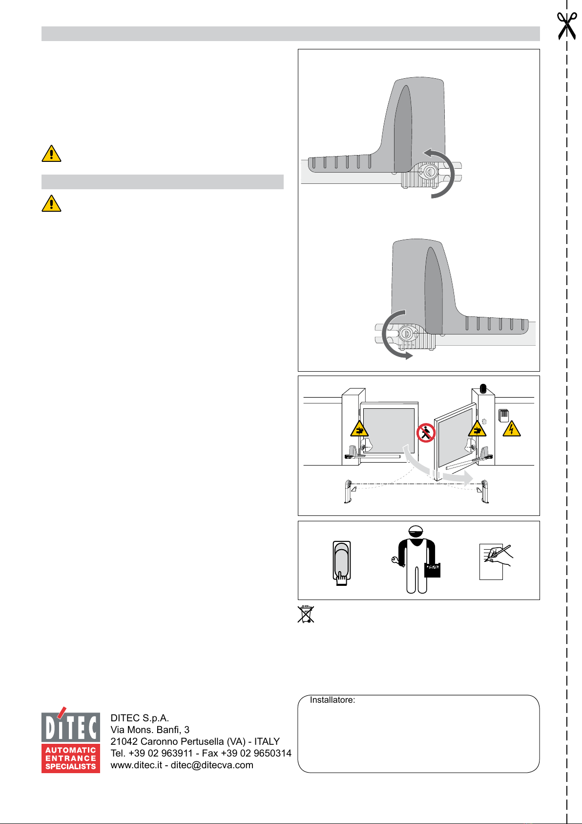
L’installatore deve fornire tutte le informazioni relative al fun-
zionamento automatico, manuale e di emergenza della porta o
cancello motorizzati, e consegnare all’utilizzatore dell’impianto
le istruzioni d’uso.
DIRETTIVA MACCHINE
Ai sensi della Direttiva Macchine (98/37/CE) l’installatore che
motorizza una porta o un cancello ha gli stessi obblighi del
costruttore di una macchina e come tale deve:
- predisporre il fascicolo tecnico che dovrà contenere i docu-
menti indicati nell’Allegato V della Direttiva Macchine;
(Il fascicolo tecnico deve essere conservato e tenuto a di-
sposizione delle autorità nazionali competenti per almeno
dieci anni a decorrere dalla data di costruzione della porta
motorizzata);
- redigere la dichiarazione CE di conformità secondo l’Allega-
to II-A della Direttiva Macchine;
- apporre la marcatura CE sulla porta motorizzata ai sensi del
punto 1.7.3 dell’Allegato I della Direttiva Macchine.
Per maggiori informazioni consultare le “Linee guida per la
realizzazione del fascicolo tecnico” disponibile su internet al
seguente indirizzo: http://www.ditec.it
INDICAZIONI DI UTILIZZO
Classe di servizio: 3 (minimo 10÷5 anni di utilizzo con
30÷60 cicli al giorno).
Utilizzo: FREQUENTE (per ingressi di tipo plurifamiliare o
piccolo condominiale con uso carraio o pedonale frequente).
- Le prestazioni di utilizzo si riferiscono al peso raccoman-
dato (circa 2/3 del peso massimo consentito). L’utilizzo con
il peso massimo consentito potrebbe ridurre le prestazioni
sopra indicate.
- La classe di servizio, i tempi di utilizzo e il numero di cicli
consecutivi hanno valore indicativo. Sono rilevati statistica-
mente in condizioni medie di utilizzo e non possono essere
certi per ogni singolo caso. Si riferiscono al periodo nel
quale il prodotto funziona senza necessità di manutenzione
straordinaria.
- Ogni ingresso automatico presenta elementi variabili quali:
attriti, bilanciature e condizioni ambientali che possono mo-
dificare in maniera sostanziale sia la durata che la qualità di
funzionamento dell’ingresso automatico o di parte dei suoi
componenti (fra i quali gli automatismi). E’ compito dell’in-
stallatore adottare coefficienti di sicurezza adeguati ad ogni
particolare installazione.
DICHIARAZIONE DEL FABBRICANTE
(Direttiva 98/37/CE, Allegato II, parte B)
Fabbricante: DITEC S.p.A.
Indirizzo: via Mons. Banfi, 3 - 21042
Caronno P.lla (VA) - ITALY
Dichiara che l’automazione per cancelli a battente serie OBBI
- è costruito per essere incorporato in una macchina o per
essere assemblato con altri macchinari per costituire una
macchina considerata dalla Direttiva 98/37/CE;
- è conforme alle condizioni delle seguenti altre direttive CE:
Direttiva compatibilità elettromagnetica 2004/108/CE;
Direttiva bassa tensione 2006/95/CE;
e inoltre dichiara che non è consentito mettere in servizio il
macchinario fino a che la macchina in cui sarà incorporata o
di cui diverrà componente sia stata identificata e ne sia stata
dichiarata la conformità alle condizioni della Direttiva 98/37/CE
e alla legislazione nazionale che la traspone.
Caronno Pertusella, Fermo Bressanini
12-02-1998 (Presidente)

8
OBBI - IP1639
I
1. DATI TECNICI
OBBI3BH OBBI3BFCH
Alimentazione 24 V= 24 V=
Assorbimento 3 A 3 A
Spinta 1500 N 1500 N
Corsa massima 350 mm 350 mm
Tempo di apertura 25 s / 90° 25 s / 90°
Classe di servizio 3 - FREQUENTE 3 - FREQUENTE
Intermittenza S2 = 30 min
S3 = 50%
S2 = 30 min
S3 = 50%
Temperatura -20° C / +55° C -20° C / +55° C
Grado di protezione IP54 IP54
Quadro elettronico E2H E2H
Indicazioni di utilizzo
m = lunghezza anta
kg = peso anta
Dimensioni
raccomandate
Dimensioni
limite
2. RIFERIMENTI ILLUSTRAZIONI
La garanzia di funzionamento e le prestazioni dichiarate si ot-
tengono solo con accessori e dispositivi di sicurezza DITEC.
2.1 Riferimentiinstallazionetipo(g.1)
[1] Radiocomando
[2] Lampeggiante
[3] Selettore a chiave
[4] Collegare l’alimentazione ad un interruttore onnipolare
con distanza d’apertura dei contatti di almeno 3 mm (non
fornito) protetto contro l’attivazione involontaria e non
autorizzata.
[5] Motoriduttore destro
[6] Motoriduttore sinistro
[7] Fotocellule
[8] Quadro elettronico
2.2 Riferimenti motoriduttore
[9] Sblocco
[10] Carter
[11] Tubo di traino
[12] Copri tubo
[13] Tappo chiusura
[14] Staffa di coda
[15] Staffa di testa
[16] Staffa aggancio guaina passacavi
3. INSTALLAZIONE
Tutte le misure riportate sono espresse in mm, salvo diversa
indicazione.
3.1 Controlli preliminari
Controllare che la struttura del cancello sia robusta e che i cardini
siano lubricati. Prevedere una battuta d’arresto in apertura e
in chiusura.
3.2 Installazione motoriduttore
- Vericare le misure di installazione (g. 3) in funzione della
distanza tra il cardine dell’anta e lo spigolo del pilastro [C]
e dell’angolo di apertura desiderato [D].
- Di serie il motoriduttore viene fornito per apertura a destra,
per convertirlo in motoriduttore per apertura a sinistra
procedere come indicato in g. 5.
- Svitare le viti di ssaggio motore.
- Estrarre il motore, il tappo del riduttore e slare il cavo
motore.
- Ruotare di 180° il riduttore.
- Con il riduttore ruotato, inserire il motore, il tappo e inlare
il cavo.
Attenzione: il motore deve essere montato in modo che il
cavo rimanga dalla parte opposta dello sblocco.
- Inserire e ssare le viti di ssaggio motore.
- Fissare la staffa di coda [14] rispettando le misure [A] e
[B] in funzione dell’angolo di apertura desiderato [D].
Sulla staffa di coda sono presenti delle forature che age-
volano il montaggio.
N.B: le misure di installazione indicate nella tabella di g. 3
consentono di scegliere i valori di [A] e [B] in base all’angolo di
apertura desiderato e in riferimento agli spazi e agli ingombri
presenti in sito.
Per avere un movimento regolare del cancello le misure [A] e
[B] devono essere uguali.
Aumentando la misura [A] si riduce la velocità di accostamento
in apertura.
Aumentando la misura [B] si riduce la velocità di accostamento
in chiusura e si aumenta la resistenza allo scasso.
Riducendolamisura[B]siaumentanoigradidiaperturadelcancello.
Le misure [A] e [B] devono comunque essere compatibili con
la corsa utile del pistone; quindi se si aumenta la misura [A] è
necessario diminuire la misura [B] e viceversa.
- Fissare il pistone alla staffa di coda [14] con il perno [F] in
dotazione (g. 6).
500 kg
400 kg
300 kg
200 kg
100 kg
m12345

9OBBI - IP1639
I
- Allungare completamente il tubo di traino [11] no alla
massima lunghezza e accorciarlo di circa 20 mm (g. 3).
Attenzione: le battute di arresto devono mantenere un
margine di corsa del tubo di traino di 10 mm sia in posizione
di anta chiusa che in posizione di anta aperta.
- Con cancello completamente chiuso posizionare la staffa
di testa [15], vericare che sia allineata a quella di coda
e ssarla al cancello.
- Fissare il pistone alla staffa di testa mediante il perno
[G] in dotazione (g. 6). Per un corretto funzionamento i
motoriduttori devono essere montati con il carter motore
in alto.
- Sbloccare il motoriduttore e vericare, muovendo ma-
nualmente il cancello, che tutta la corsa avvenga senza
interferenze. Lubricare leggermente gli snodi anteriori e
posteriori.
- Assemblare il copri tubo [12] con il tappo [13] e la guarni-
zione e ssarlo con le viti [H] in dotazione (g. 7).
Attenzione al verso di inserimento. Le feritoie presenti sul
tappo di chiusura [13] devono trovarsi sulla parte inferiore
in modo da favorire la fuoriuscita d’acqua.
- Montare il carter [10] ssandolo con la vite [N], facendo
attenzione al posizionamento del cavo.
3.3 RegolazionenecorsaOBBI3BFCH
Il motoriduttore OBBI3BFCH è dotato di necorsa magnetici.
Regolare i necorsa in modo di ottenere la corretta apertura e
chiusura dell’automazione come indicato in g. 9-10.
4. COLLEGAMENTI ELETTRICI
Il motoriduttori OBBI3BH-OBBI3BFCH possono essere collegati
al quadro elettronico E2H.
I collegamenti elettrici e l’avviamento dei motoriduttori OBBI3BH
e OBBI3BFCH sono illustrati in g. 8 e nel manuale di installa-
zione del quadro elettronico E2H.
5. PIANODIMANUTENZIONE(ogni6mesi)
Togliere alimentazione 230 V~ e batterie (se presenti):
- Pulire e lubricare, con grasso neutro, i perni di rotazione,
i cardini del cancello e la vite di traino.
- Vericare la tenuta dei punti di ssaggio.
- Controllare il buono stato dei collegamenti elettrici.
Ridare alimentazione 230 V~, e batterie (se presenti):
- Vericare le regolazioni di forza.
- Controllare il corretto funzionamento di tutte le funzioni di
comando e sicurezza (fotocellule).
- Controllare il corretto funzionamento del sistema di sblocco.
- Vericare il funzionamento delle batterie (in continuità) se
presente il quadro elettronico E2H. Togliendo alimenta-
zione ed effettuando alcune manovre in successione. Al
termine ricollegare l’alimentazione 230 V~.
ATTENZIONE: Per le parti di ricambio fare riferimento al listino
ricambi.

PISTONE DESTRO
PISTONE SINISTRO
DITEC S.p.A.
Via Mons. Ban, 3
21042 Caronno Pertusella (VA) - ITALY
Tel. +39 02 963911 - Fax +39 02 9650314
Installatore:
ON
OFF
DA STACCARE E CONSEGNARE ALL’UTILIZZATORE
ISTRUZIONI D’USO AUTOMAZIONE PER CANCELLI A BATTENTE OBBI
ISTRUZIONI DI SBLOCCO
In caso di guasto o in mancanza di tensione, sbloccare l’even-
tuale elettroserratura, inserire la chiave e ruotarla in senso
antiorario (nel senso indicato dalla freccia sul motoriduttore).
Aprire manualmente il cancello.
Per ribloccare le ante girare la chiave in senso orario (in senso
contrario alla freccia sul motoriduttore). Per facilitare l’operazione
muovere leggermente l’anta.
Attenzione: eseguire le operazioni di blocco e sblocco
ante a motore fermo.
AVVERTENZE GENERALI PER LA SICUREZZA
Le presenti avvertenze sono parte integrante ed essenziale
del prodotto e devono essere consegnate all’utilizzatore.
Leggerle attentamente in quanto forniscono importanti indicazio-
ni riguardanti la sicurezza di installazione, uso e manutenzione.
È necessario conservare queste istruzioni e trasmetterle ad
eventuali subentranti nell’uso dell’impianto.
Questo prodotto dovrà essere destinato solo all’uso per il quale
è stato espressamente concepito. Ogni altro uso è da consi-
derarsi improprio e quindi pericoloso. Il costruttore non può
essere considerato responsabile per eventuali danni causati
da usi impropri, erronei ed irragionevoli. Evitare di operare in
prossimità delle cerniere o organi meccanici in movimento. Non
entrare nel raggio di azione della porta o cancello motorizzati
mentre è in movimento.
Non opporsi al moto della porta o cancello motorizzati poiché
può causare situazioni di pericolo. Non permettere ai bambini di
giocare o sostare nel raggio di azione della porta o cancello mo-
torizzati. Tenere fuori dalla portata dei bambini i radiocomandi e/o
qualsiasi altro dispositivo di comando, per evitare che la porta o
cancello motorizzati possa essere azionata involontariamente.
In caso di guasto o di cattivo funzionamento del prodotto, disin-
serire l’interruttore di alimentazione, astenendosi da qualsiasi
tentativo di riparazione o di intervento diretto e rivolgersi solo a
personale professionalmente competente.
Il mancato rispetto di quanto sopra può creare situazioni di
pericolo.
Qualsiasi intervento di pulizia, manutenzione o riparazione, deve
essere effettuato da personale professionalmente competente.
Per garantire l’efcienza dell’impianto ed il suo corretto funziona-
mento è indispensabile attenersi alle indicazioni del costruttore
facendo effettuare da personale professionalmente competente
la manutenzione periodica della porta o cancello motorizzati.
In particolare si raccomanda la verica periodica del corretto
funzionamento di tutti i dispositivi di sicurezza. Gli interventi
di installazione, manutenzione e riparazione devono essere
documentati e tenuti a disposizione dell’utilizzatore. Per un corretto smaltimento delle apparecchiature elettriche
ed elettroniche, delle pile e degli accumulatori, l’utilizzatore
deve consegnare il prodotto presso gli appositi “centri di raccolta
differenziata” predisposti dalle amministrazioni comunali.

GB
11 OBBI - IP1639
GENERAL SAFETY PRECAUTIONS
This installation manual is intended for professionally
competent personnel only.
The installation, the electrical connections and the settings
must be completed in conformity with good workmanship and
with the laws in force. Read the instructions carefully before
beginning to install the product. Incorrect installation may be a
source of danger. Packaging materials (plastics, polystyrene,
etc) must not be allowed to litter the environment and must
be kept out of the reach of children for whom they may be a
source of danger. Before beginning the installation check that
the product is in perfect condition. Do not install the product in
explosive areas and atmospheres: the presence of flammable
gas or fumes represents a serious threat to safety.
Before installing the motorisation device, make all the structu-
ral modifications necessary in order to create safety clerance
and to guard or isolate all the compression, shearing, trapping
and general danger areas. Check that the existing structure
has the necessary strength and stability. The manufacturer
of the motorisation device is not responsible for the non-
observance of workmanship in the costruction of the frames to
be motorised , nor for deformations that may be occur during
use. The safety devices (photoelectric cells, mechanical ob-
struction sensor, emergency stop, etc) must be installed taking
into account: the provisions and the directives in force, good
workmanship criteria, the installation area, the funtional logic
of the system and the forces developed by the motorised door
or gate. The safety devices must protect against compression,
shearing, trapping and general danger areas of the motorized
door or gate. Display the signs required by law to identify dan-
ger areas. Each installation must bear a visible indication of the
data identifying the motorised door or gate.
Before connecting to the mains check that the rating is
correct for the destination power requirements.
A multipolar isolation switch with minimum contact gaps of 3
mm must be included in the mains supply.
Check that upstream of the electrical installation there is an
adequate differential switch and a suitable circuit breaker.
When requested, connect the motorized door or gate to an
effective earthing system carried out as indicated by current
safety standards. During installation, maintenance and repair
operations, cut off the power supply before opening the cover
to access the electrical parts.
The electronic parts must be handled using earthed
antistatic conductive arms. The manufacturer of the
motorising device declines all responsability in cases where
components which are incompatible with the safe and cor-
rect operation of the product only original spare parts must
be used. For repairs or replacements of products only original
spare parts must be used. The fitter must supply all information
corcerning the automatic, the manual and emergency opera-
tion of the motorised door or gate, and must provide the user
the device with the operating instructions. It is recommended
that antistatic conductive earthed arm bands be worn when
manipulating electronic parts.
MACHINERY DIRECTIVE
Pursuant to Machine Directive (98/37/EC) the installer who mo-
torises a door or gate has the same obligations as a machine
manufacturer and shall:
- prepare technical documentation containing the documents
indicated on Schedule V of the Machine Directive;
(The technical documentation shall be kept and placed at
the disposal of competent national authorities for at least ten
years starting on the date of manufacture of the motorised
door);
- draw up the EC declaration of conformity according to Sche-
dule II-A of the Machine Directive;
- affix the CE mark on the motorised door pursuant to para.
1.7.3 of Schedule I of the Machine Directive.
For more details, refer to the “Guidelines for producing tech-
nical documentation” available on Internet at the following
address: www.ditec.it
APPLICATIONS
Service life: 3 (minimum 10÷5 years of working life with 30÷60
cycles a day)
Applications: FREQUENT (For vehicle or pedestrian accesses
to town houses or small condominiums with frequent use).
- Performance characteristics are to be understood as refer-
ring to the recommended weight (approx. 2/3 of maximum
permissible weight). A reduction in performance is to be ex-
pected when the access is made to operate at the maximum
permissible weight.
- Service class, running times, and the number of consecu-
tive cycles are to be taken as merely indicative having been
statistically determined under average operating conditions,
and are therefore not necessarily applicable to specic condi-
tions of use. During given time spans product performance
characteristics will be such as not to require any special
maintenance.
- The actual performance characteristics of each automatic
access may be affected by independent variables such as
friction, balancing and environmental factors, all of which
may substantially alter the performance characteristics of the
automatic access or curtail its working life or parts thereof
(including the automatic devices themselves). When setting
up, specic local conditions must be duly borne in mind and
the installation adapted accordingly for ensuring maximum
durability and trouble-free operation.
DECLARATION BY THE MANUFACTURER
(Directive 98/37/EC, Annex II, sub B)
Manufacturer: DITEC S.p.A.
Address: via Mons. Banfi, 3 - 21042
Caronno P.lla (VA) - ITALY
Herewith declares that the electromechanical automatic sy-
stem series OBBI:
- is intended to be incorpored into machinery or to be
assembled with other machinery to constitute machinery
convered by Directive 98/37/EC;
- is in conformity with the provisions of the following other EC
directives:
Electromagnetic Compatibility Directive 2004/108/EC;
Low Voltage Directive 2006/95/EC;
and furthermore declares that it is not allowed to put the machi-
nery into service until the machinery into which it is to be incor-
porated or of which it is to be a component has been found and
declared to be in conformity with the provisions of Directive
98/37/EC and with national implementing legislation.
Caronno Pertusella, Fermo Bressanini
12-02-1998 (President)

GB
12
OBBI - IP1639
1. TECHNICAL DATA
OBBI3BH OBBI3BFCH
Power supply 24 V= 24 V=
Absorption 3 A 3 A
Thrust 1500 N 1500 N
Max run 350 mm 350 mm
Openingtime 25 s / 90° 25 s / 90°
Service class 3 - FREQUENT 3 - FREQUENT
Intermittence S2 = 30 min
S3 = 50%
S2 = 30 min
S3 = 50%
Temperature -20° C / +55° C -20° C / +55° C
Degreeofprotection IP54 IP54
Control panel E2H E2H
Applications
m = leaf width
kg = leaf weight
Recommended
dimensions
Limit dimensions
2. REFERENCE TO ILLUSTRATIONS
The given operating and performance features can only be
guaranteed with the use of DITEC accessories and safety
devices.
2.1 Standardinstallationreferences(g.1)
[1] Radio
[2] Flashing light
[3] Key selector
[4] Connect power supply to a type-approved omnipolar switch
with a contact opening gap of no less that 3 mm (not
supplied) protected against accidental and unauthorized
activation.
[5] Right geared motor
[6] Left geared motor
[7] Photocells
[8] Control panel
2.2 Geared motor references
[9] Release
[10] Housing
[11] Draft tube
[12] Tube cover
[13] Closing plug
[14] Tail bracket
[15] Head bracket
[16] Cable guide sheat hooking bracket
3. INSTALLATION
Unless otherwise specied, all measurements are expressed
in millimetres (mm).
3.1 Preliminary checks
Check that the structure is sufciently rugged and that the hinge
pivots are properly lubricated. Provide an opening and closing
stop.
3.2 Geared motor installation
- Check the installation measurements (g.3) on the basis
of the distance between the hinge of the door wing and the
corner of the pillar [C] and of the desired opening angle
[D].
- The geared motor is supplied as standard with right-hand
opening. To convert it for left-hand opening, proceed as
indicated in g.5.
- Loosen the motor fastening screws.
- Extract the motor and the reducer cap and unthread the
motor cable.
- Rotate the reduction gear by 180°.
- With the reduction gear rotated, insert the motor and cap,
and insert the cable.
Attention: the motor must be assembled so that the cable
remains on the side opposite the release.
- Insert and x the motor fastening screws.
- Fix the tail bracket [14], respecting measurements [A] and
[B] on the basis of the desired opening angle [D].
On the tail bracket there are holes that facilitate the as-
sembly operation.
Note: the installation measurements indicated in the table of g.3
allow you to choose the values of [A] and [B] on the basis of the
desired opening angle and in relation to the on site spaces and
overall dimensions.
Increasing [A] decreases the coming up speed during opening.
Increasing [B] decreases the coming up speed during closing
and improves burglar-proong.
Reducing [B] increases the extent of gate opening.
Measurements [A] and [B] must in any case be compatible with
the useful travel of the piston so that; if [A] is increased, [B] must
be decreased and vice versa.
- Fix the piston to the rear bracket [14] with the pin [F] sup-
plied (g.6).
500 kg
400 kg
300 kg
200 kg
100 kg
m12345

GB
13 OBBI - IP1639
- Extend the haulage tube completely [11] to its maximum
length, then shorten it by approximately 20mm (g.3).
Attention: the stops must keep a 10 mm margin of tube
stroke, in both the door wing closed and door wing open
positions.
- With the gate completely closed, position the front bracket
[15], check it is aligned with the rear bracket and x it to
the gate.
- Fix the piston to the front bracket with the pin [G] supplied
(g.6). To work correctly, the gearmotors must be assem-
bled with the motor casing at the top.
- Unblock the gearmotor and check (moving the gate ma-
nually) the entire stroke is free of interference. Slightly
lubricate the front and rear articulated joints.
- Assemble the tube cover [12] with the cap [13] and seal,
and x it with the screws [H] supplied (g.7).
Pay attention to the insertion direction. The slits on the
closing cap [13] must be on the lower part in order to help
the water to come out.
- Assemble the casing [10], xing it with the screw [N], paying
attention to the positioning of the cable.
3.3 OBBI3BFCH limit switch adjustment
The OBBI3BFCH geared motor is tted with magnetic limit
switches. Adjust the limit switches in order to obtain the cor-
rect opening and closing of the automation, as indicated in g.
9-10.
4. ELECTRICAL CONNECTIONS
The gearmotors OBB13BH-OBB13BFCH can be connected to
the E2H control panel.
The electrical wiring and the start-up of the gearmotors OBBI3BH
and OBBI3BFCH are shown in g.8 and in the installation
manuals of the E2H control panel.
5. MAINTENANCEPROGRAM(every6months)
Disconnect the 230 V~ power supply and batteries if present:
- Clean and lubricate, using neutral grease, the turning pins,
the hinges of the gate and the drive screw
- Check that fastening points are properly tightened.
- Check the electrical wiring is in good condition.
Reconnect the 230 V~ power supply and batteries if present:
- Check the power adjustments.
- Check the good operation of all command and safety
functions (photocells).
- Check the good operation of the release.
- If the E2H control panel is mounted, check for battery
continuity by powering off and performing several
manoeuvres in sequence. Upon test completion, power
back on (230 V~).
ATTENTION: For spare parts, see the spares price list.

RIGHT PISTON
LEFT PISTON
DITEC S.p.A.
Via Mons. Ban, 3
21042 Caronno Pertusella (VA) - ITALY
Tel. +39 02 963911 - Fax +39 02 9650314
Installer:
ON
OFF
TEAR OFF AND DELIVER TO USER
OPERATING INSTRUCTIONS FOR SWING GATES AUTOMATION OBBI
RELEASE INSTRUCTION
In the event of a fault or blackout, release any electric lock, insert
the key and turn it anticlockwise (in the direction indicated by the
arrow on the gearmotor). Manually open the gate.
To block the door wings again, turn the key clockwise (in the
opposite direction to the arrow on the gearmotor). To facilitate
the operation, move the door wing slightly.
Attention: the door wing block and release operations must
be performed with the motor idle.
GENERAL SAFETY PRECAUTIONS
The following precautions are an integral and essential part
of the product and must be supplied to the user.
Read them carefully as they contain important indications for
the safe installation, use and maintenace.
These instruction must be kept and forwarded to all possible
future user of the system.
This product must be used only for that which it has been ex-
pressely designed.
Any other use is to be considered improper and therefore dan-
gerous.
The manufacturer cannot be held responsible for possible da-
mage caused by improper, erroneous or unresonable use.
Avoid operating in the proximity of the hinges or moving mecha-
nical parts.
Do not enter the eld of action of the motorised door or gate
while in motion.
Do not obstruct the motion of the motorised door or gate as this
may cause a situation of danger.
Do not lean against or hang on to the barrier when it is moving.
Do not allow children to play or stay within the eld of action of
the motorised door or gate.
Keep remote control or any other control devices out of the reach
of children, in order to avoid possible involuntary activation of
the motorised door or gate.
In case of breack down or malfunctioning of the product, discon-
nect from mains, do not attempt to repair or intervene directly
and contact only qualied personnel.
Failure to comply with the above may create a situation of
danger.
All cleaning, maintenance or repair work must be carried out by
qualied personnel.
In order to guarantee that the system works efciently and cor-
rectly it is indispensable to comply with the manufacturer’s indi-
cations thus having the periodic maintenance of the motorised
door or gate carried out by qualied personnel.
In particular regular checks are recommended in order to verify
that the safety devices are operating correctly. All installation,
maintenance and repair work must be documented and made
available to the user.
For the correct disposal of electric and electronic equip-
ment, waste batteries and accumulators, the user must take
such products to the designated municipal collection facilities.

F
15 OBBI - IP1639
CONSIGNES GENERALES DE SECURITE
Le présent manuel d’installation s’adresse exclusivement
à un personnel qualié.
L’installation, les branchements électriques et les réglages
doivent être effectués conformément à la bonne pratique et aux
normes en vigueur. Lire attentivement les instructions avant de
commencer l’installation du produit. Une mauvaise installation
peut être source de danger. Ne pas jeter dans la nature les
matériaux qui composent l’emballage (plastique, polystyrène,
etc.) et ne pas les laisser à la portée des enfants car ils sont une
source potentielle de danger. Avant de commencer l’installation,
vérier l’intégrité du produit.
Ne pas installer le produit en atmosphère et environnement
explosifs: la présence de gaz ou de fumées inammables
constitue un grave danger pour la sécurité. Avant d’installer
la motorisation, apporter toutes les modications structurelles
relatives à la réalisation des distances minimales de sécurité et
à la protection ou séparation de toutes les zones d’écrasement,
cisaillement, entraînement et de danger en général.
Vérier que la structure existante remplit les prescriptions de
robustesse et stabilité.
Le fabricant de la motorisation décline toute responsabilité quant
à l’inobservation de la bonne pratique dans la construction des
portes et portails à motoriser, et aux déformations qui pourraient
se produire au cours de l’utilisation.
Les dispositifs de sécurité (cellules photoélectriques, bourrelets
sensibles, arrêt d’urgence, etc.) doivent être installés en tenant
compte : des réglementations et directives en vigueur, des
règles de la bonne pratique, de l’environnement d’installation,
de la logique de fonctionnement du système et des forces
développées par la porte ou le portail motorisé.
Les dispositifs de sécurité doivent protéger toutes zones
d’écrasement, cisaillement, entraînement et de danger en
général, de la porte ou du portail motorisé. Appliquer les
signalisations prévues par les normes en vigueur pour signaler
les zones dangereuses.
L’indication des données d’identication de la porte ou du portail
motorisé doit être visible sur chaque installation.
Avant de mettre sous tension, s’assurer que les données
gurant sur la plaque signalétique correspondent à celles
du secteur.
Prévoir sur le réseau d’alimentation un interrupteur/sectionneur
omnipolaire avec une distance d’ouverture des contacts égale ou
supérieure à 3 mm. Vérier la présence en amont de l’installation
électrique d’un disjoncteur différentiel et d’une protection contre
la surintensité adéquats.
Si nécessaire, raccorder la porte ou le portail motorisé à une
installation de mise à la terre réalisée conformément aux
prescriptions des normes de sécurité en vigueur. Au cours
des interventions d’installation, entretien et réparation, couper
l’alimentation avant d’ouvrir le couvercle pour accéder aux
parties électriques.
N’effectuer la manipulation des parties électroniques
qu’après s’être muni de bracelets conducteurs antistatiques
reliés à la terre. Le fabricant de la motorisation décline toute
responsabilité quant à la sécurité et au bon fonctionnement si des
composants incompatibles sont installés. En cas de réparation
ou de remplacement des produits, utiliser exclusivement les
pièces de rechange DITEC.
L’installateur doit fournir toutes les informations relatives au
fonctionnement automatique, manuel et d’urgence de la porte
ou du portail motorisé, et remettre le mode d’emploi à l’utilisateur
de l’installation.
DIRECTIVE MACHINE
Selon la Directive Machine (98/37/CE) l’installateur qui “moto-
rise” une porte ou un portail a les mêmes obligations du fabricant
d’une machine et donc il doit:
- prédisposer le dossier technique qui doit contenir les docu-
ments indiqués dans l’annex V de la Directive Machine.
(le dossier technique doit être gardé et tenu a dispositions
des organes de contrôle nationaux pour au moins dix ans
après la date de la fabrication de la porte motorisée);
- faire la déclaration CE de conformité selon l’annex II-A de la
Directive Machine et la remettre au client;
- afcher le marquage CE sur la porte motorisée selon le point
1.7.3.de l’annex I de la Directive Machine.
Pour tout renseignement complémentaire, consulter le document
“Lignes directrices pour la réalisation du fascicule technique”
disponible sur Internet á l’adresse suivante: www.ditec.it
MODE D’EMPLOI
Classe de service: 3 (minimum 10÷5 ans d’utilisation avec
30÷60 cycles par jour)
Utilisation: FREQUENT (Pour installations domestiques ou
petits immeubles avec passage pour véhicules ou passage
piétons fréquent).
- Les performances d’utilisation se réfèrent au poids recom-
mandé (environ 2/3 du poids maximum admis). L’utilisation
avec le poids maximum admis peut entraîner une diminution
des performances ci-dessus.
- La classe de service, les temps d’utilisation et le nombre de
cycles consécutifs sont donnés à titre indicatif. Il s’agit de va-
leurs relevées statistiquement dans des conditions moyen-
nes d’utilisation, n’offrant donc pas une précision absolue
pour chaque cas spécifique. Ces valeurs se réfèrent à la
période pendant laquelle le produit fonctionne sans aucune
intervention d’entretien exceptionnel.
- Tout accès automatique présente des éléments variables
tels que: frottements, compensations et conditions environ-
nementales pouvant modifier fondamentalement aussi bien
la durée que la qualité de fonctionnement de l’accès auto-
matique ou d’une partie de ses éléments (entre autres, les
automatismes). L’installateur est tenu d’adopter des coeffi-
cients de sécurité adaptés à chaque installation spécifique.
DECLARATION DU FABRICANT
(Directive 98/37/CE, Annex II, Chapitre B)
Fabricant: DITEC S.p.A.
Adresse: via Mons. Ban, 3 - 21042
Caronno P.lla (VA) - ITALY
Déclare ci-après que le systéme série OBBI
- est prévue pour être incorporée dans une machine ou être
assemblée avec d’autres machines pour constituer une
machine couverte par la directive 98/37/CE;
- est conforme aux dispositions des directives CE suivantes:
Directive compatibilitè électromagnetique 2004/108/CE;
Directive basse tension 2006/95/CE;
et déclare par ailleurs qu’il est interdit de mettre la machine en
service avant que la machine dans laquelle elle sera incorporée
ou dont elle constitue une partie ait été considérée et déclarée
conforme aux dispositions de la Directive 98/37/CE et aux lé-
gislations nationales la transposant.
Caronno Pertusella, Fermo Bressanini
12-02-1998 (Presidént)

F
16
OBBI - IP1639
1. DONNEES TECNIQUES
OBBI3BH OBBI3BFCH
Alimentation 24 V= 24 V=
Absorption 3 A 3 A
Poussée 1500 N 1500 N
Course max 350 mm 350 mm
Temps de ouverture 25 s / 90° 25 s / 90°
Classe de service 3 - FREQUENT 3 - FREQUENT
Intermittence S2 = 30 min
S3 = 50%
S2 = 30 min
S3 = 50%
Temperateur -20° C / +55° C -20° C / +55° C
Degrèdeprotection IP54 IP54
Armoire electronique E2H E2H
Indications d’utilisation
m = longueur du vantail
kg = poids du vantail
Dimensions
recommandées
Dimensions
limites
2. REFERENCES ILLUSTRATIONS
La garantie de fonctionnement et les performances déclarées
ne peuvent être obtenues qu’en utilisant les accessoires et les
dispositifs de sécurité DITEC.
2.1 Référencesinstallationtype(g.1)
[1] Radiocommande
[2] Lampe clignotante
[3] Sélecteur à clé
[4] Relier l’alimentation à un interrupteur unipolaire avec
distance d’ouverture des contacts d’au moins 3 mm (non
fourni) protégé contre l’activation involontaire et non au-
torisée.
[5] Motoréducteur droit
[6] Motoréducteur gauche
[7] Photocellules
[8] Armoire electronique
2.2 Références motoréducteur
[9] Déblocage
[10] Couvercle
[11] Tube d’entraînement
[12] Couvre-tube
[13] Bouchon de fermeture
[14] Patte posterieure
[15] Patte antérieure
[16] Bride d’attache de la gaine passe-câble
3. INSTALLATION
Toutes les mesures reportées sont exprimées en millimètres
(mm), à moins d’indications différentes.
3.1 Contrôles préliminaires
Contrôler que la structure est robuste et que les gonds sont
bien graissés. Prévoir une butée d’arrêt à l’ouverture et à la
fermeture.
3.2 Installation du motoréducteur
- Contrôler les mesures de l’installation (g. 3) en fonction
de la distance qui existe entre le gond du vantail et l’arête
du poteau [C] et de l’angle d’ouverture désiré [D].
- Le motoréducteur de série est fourni pour les ouvertures à
droite, pour le convertir en motoréducteur pour ouverture
à gauche suivre les indications de la g. 5.
- Dévisser les vis de xation du moteur.
- Enlever le moteur, le bouchon du réducteur et dégager
le câble du moteur.
- Faire tourner le réducteur de 180°.
- Après avoir fait tourner le réducteur, remettre le moteur,
le bouchon et enler le câble.
Attention : le moteur doit être monté de manière à ce que
le câble reste de la partie opposée au déverrouillage.
- Insérer et xer les vis de xation du moteur.
- Fixer la patte posterieure [14] en respectant les mesures
[A] et [B] en fonction de l’angle d’ouverture désiré [D].
Sur la patte posterieure il y a des trous pour faciliter le
montage.
Remarque: les mesures de l’installation qui sont indiquées dans
le tableau de la g. 3 permettent de choisir les valeurs de [A] et
[B] en fonction de l’angle d’ouverture désiré et en référence aux
espaces et aux encombrements qui se trouvent sur le site.
Pour que le mouvement du portail soit régulier les mesures [A]
et [B] doivent être égales.
En augmentant la mesure [A] on réduit la vitesse de rapproche-
ment en ouverture.
En augmentant la mesure [B] on réduit la vitesse de rapproche-
ment en fermeture et on augmente la résistance à l’effraction.
En augmentant la mesure [B] on augmente les degrés d’ouver-
ture du portail.
Les mesures [A] et [B] doivent de toute manière être compatibles
avec la course utile du piston; ce qui fait que si l’on augmente la
mesure [A] il faut diminuer la mesure [B] et vice-versa.
- Fixer le piston à la patte posterieure [14] avec l’axe [F]
fourni avec l’équipement (g. 6).
500 kg
400 kg
300 kg
200 kg
100 kg
m12345

F
17 OBBI - IP1639
- Allonger le tube d’entraînement [11] le plus possible et le
raccourcir de 20 mm environ (g. 3).
Attention les butées d’arrêt doivent conserver une marge
de course du tube d’entraînement de 10 mm aussi bien
en position de vantail fermé que de vantail ouvert.
- Avec le vantail complètement fermé positionner la patte
antérieure [15], contrôler si elle est bien alignée avec celle
posterieure et la xer au vantail.
- Fixer le piston à la patte antérieure avec le pivot [G]
fourni (g. 6). Pour garantir un bon fonctionnement les
motoréducteurs doivent être montés avec le carter du
moteur en haut.
- Débloquer le motoréducteur et contrôler, en déplaçant le
portail à la main, si toute la course se fait sans aucune
interférence. Lubrier légèrement les articulations avant
et arrière.
- Assembler le couvre-tube [12] avec le bouchon [13] et le
joint et le xer avec les vis [H] fournies avec l’équipement
(g. 7).
Attention au sens d’introduction. Les ouvertures sur le
bouchon de fermeture [13] doivent se trouver dans la partie
inférieure pour permettre à l’eau de s’écouler.
- Monter le carter [10] en le xant avec la vis [N], en faisant
attention au positionnement du câble.
3.3 RéglagendecourseOBBI3BFCH
Le motoréducteur OBBI3BFCH est équipé de ns de course
magnétiques. Régler les ns de course de manière à obtenir une
ouverture et une fermeture correcte de l’automatisme comme
indiqué sur la g. 9-10.
4. RACCORDEMENTS ELECTRIQUES
Le motoréducteur OBBI3BH-OBBI3BFCH peut être raccordé au
armoire électronique E2H.
Les raccordements électriques et la mise en marche des mo-
toréducteurs OBBI3BH et OBBI3BFCH sont illustrés dans la g. 8
et dans le manuel d’installation de l’armoire électronique E2H.
5. ENTRETIENPERIODIQUE(tousles6mois)
Couper l’alimentation 230 V~ et batteries si présentes:
- Nettoyer et graisser, avec de la graisse neutre, les axes
de rotation, les gonds du portail et la vis d’entraînement.
- Vérier la tenue des points de xation.
- Contrôler le bon état des raccordements électriques.
Remettre l’alimentation 230 V~ et batteries si présentes:
- Contrôler les réglages de force.
- Contrôler le bon fonctionnement de toutes les fonctions
de commande et de sécurité (photocellules).
- Contrôler le bon fonctionnement du systéme de déver-
rouillage.
- Vérifier le fonctionnement des batteries (en continu)
en présence de l’armoire électronique E2H en coupant
l’alimentation et en effectuant quelques manœuvres con-
sécutives. Après quoi, rebrancher l’alimentation 230 V~.
ATTENTION: Pour les pièces de rechange, se reporter au ca-
talogue spécique.

PISTON DROIT
PISTON GAUCHE
DITEC S.p.A.
Via Mons. Ban, 3
21042 Caronno Pertusella (VA) - ITALY
Tel. +39 02 963911 - Fax +39 02 9650314
Installateur:
ON
OFF
A DETACHER ET REMETTRE A L’UTILISATEUR
MODE D’EMPLOI DE L’AUTOMATISME POUR PORTAILS BATTANTS OBBI
OPERATIONS DE DEVERROUILLAGE
En cas de panne ou de coupure de courant, déverrouiller la
serrure électrique éventuelle, introduire la clé et la tourner
dans le sens contraire à celui des aiguilles d’une montre (dans
le sens indiqué par la èche sur le motoréducteur). Ouvrir le
portail à la main.
Pour rebloquer les vantaux tourner la clé dans le sens des ai-
guilles d’une montre (dans le sens contraire à celui indiqué par
la èche sur le motoréducteur). Pour faciliter l’opération déplacer
légèrement le vantail.
Attention: effectuer les opérations de verrouillage et déver-
rouillage du vantail avec le moteur arrêté.
CONSIGNES GENERALES DE SECURITE
Les présentes consignes sont une partie intégrante
et essentielle du produit, et elles doivent être remises
à l’utilisateur. Les lire attentivement car elles contiennent
d’importantes indications concernant la sécurité d’installation,
utilisation et entretien.
Conserver ces instructions et les transmettre à de nouveaux
utilisateurs de l’installation.
Ce produit est exclusivement destiné à l’usage pour lequel il a
été expressément conçu.
Un tout autre usage est impropre et par conséquent dangereux.
Le fabricant décline toute responsabilité quant aux préjudices
causés par des usages impropres, erronés et déraisonnables.
Ne pas opérer à proximité des charnières ou des organes
mécaniques en mouvement.
Ne pas entrer dans le rayon d’action de la porte ou du portail
motorisé en mouvement.
Ne pas s’opposer au mouvement de la porte ou du portail
motorisé car ceci peut générer des situations de danger.
Interdire aux enfants de jouer ou de s’arrêter dans le rayon
d’action de la porte ou du portail motorisé.
Conserver les radiocommandes et/ou tout autre dispositif de
commande hors de la portée des enfants, an d’éviter que la
porte ou le portail motorisé ne soit actionné involontairement.
En cas de panne ou de mauvais fonctionnement du produit,
déconnecter l’interrupteur de mise sous tension, ne pas réparer
ou intervenir directement, et s’adresser exclusivement à un
personnel qualié.
L’inobservation de ces consignes peut générer des situations de
danger. Les interventions de nettoyage, entretien ou réparation,
doivent être effectuées par un personnel qualié.
Pour garantir l’efcacité de l’installation et son bon fonctionnement,
respecter scrupuleusement les indications du fabricant, en
faisant effectuer l’entretien périodique de la porte ou du portail
motorisé par un personnel qualié.
Il est notamment recommandé de vérier périodiquement le bon
fonctionnement de tous les dispositifs de sécurité.
Les interventions d’installation, entretien et réparation doivent
être attestées par des documents tenus à disposition de
l’utilisateur.
Pour effectuer un recyclage correct des appareils électriques
et électroniques, des piles et des accumulateurs, l’utilisateur
devra déposer le produit auprès des “centres de tri sélectif”
appropriés, prévus par les administrations communales.

D
19 OBBI - IP1639
ALLGEMEINE SICHERHEITSHINWEISE
Diese Montageanleitungen sind ausschließlich dem
Fachpersonal vorbehalten.
Die Montage, elektrischen Anschlüsse und Einstellungen
sind unter Beachtung der technischen Verhaltensregeln und
Einhaltung der geltenden Normen auszuführen.
Lesen Sie die Anleitungen vor der Montage des Produkts
aufmerksam durch. Eine fehlerhafte Montage kann zu
ernsthaften Verletzungen und Sachschäden führen. Die
Verpackungsmaterialien (Kunststoff, Styropor etc.) müssen
sachgemäß entsorgt werden und dürfen nicht in Kinderhände
gelangen, da sie eine Gefahrenquelle darstellen können.
ÜberprüfenSiedas Produkt vorderMontage aufTransportschäden.
Montieren Sie das Produkt nicht in explosionsfähigerAtmosphäre
oder Umgebung: Das Vorhandensein von entzündlichen Gasen
oder Dämpfen bedeutet eine große Gefahr. Stellen Sie sicher,
dass der Montageuntergrund den nötigen Anforderungen im
Hinblick auf Robustheit und Stabilität entspricht. Der Hersteller
des Antriebs schließt eine Haftungsübernahme im Falle der
Nichtbeachtung der technischen Verhaltensregeln bei der
Fertigung und Montage aus.
Beachten Sie bei der Montage der Schutzeinrichtungen
(Lichtschranken, Kontaktleisten, Not-Stopps etc.) unbedingt die
geltenden Normen und Richtlinien, die Kriterien der technischen
Verhaltensregeln, die Montageumgebung, die Betriebslogik des
Systems und die vom motorisierten Tor entwickelten Kräfte.
Die Schutzeinrichtungen müssen mögliche Quetsch-, Scher-
Einzieh- und allgemeine Gefahrenstellen des motorisierten Tors
sichern. Bringen Sie die den Vorschriften entsprechenden Warn-
und Hinweiszeichen zur Kennzeichnung von Gefahrenstellen
an. Bei jeder Installation müssen die Identikationsdaten des
motorisierten Tors an sichtbarer Stelle angebracht werden.
Stellen Sie vor dem elektrischen Anschluss sicher, dass
die Angaben auf dem Typenschild mit den Werten des
Stromnetzes übereinstimmen. Statten Sie das Versorgungsnetz
mit einem allpoligen Trennschalter mit Kontaktöffnungsabstand
von mindestens 3 mm aus. Stellen Sie sicher, dass der
elektrischen Anlage ein geeigneter Fehlerstrom-Schutzschalter
und ein Überstromschutz vorgeschaltet sind. Schließen Sie
das motorisierte Tor soweit erforderlich an eine normgerechte
Erdungsanlage an. Unterbrechen Sie während der Montage-,
Wartungs- oder Reparaturarbeiten die Stromzufuhr, bevor
Sie den Deckel für den Zugang zu den elektrischen Geräten
öffnen.
Eingriffe an den elektronischen Geräten dürfen nur mit
antistatischem geerdeten Armschutz vorgenommen
werden. Der Hersteller des Antriebs lehnt jede Haftung für die
Installation von sicherheits- und betriebstechnisch ungeeigneten
Bauteilen ab. Bei Reparaturen oder Austausch der Produkte
dürfen ausschließlich Original-Ersatzteile verwendet werden.
Der Monteur ist verpichtet, dem Betreiber der Anlage alle
erforderlichen Informationen zum automatischen, manuellen
und Notbetrieb des motorisierten Tors zu liefern und die
Betriebsanleitung auszuhändigen.
MASCHINENRICHTLINIE
Gemäß Maschinenrichtlinie (98/37/EG) ist der Installateur, der
eine Tür oder ein Tor motorisiert, den gleichen Verpichtungen
unterlegen wie ein Maschinenhersteller und hat somit folgendes
zu tun:
- Erstellung der technischen Akte, welche die in Anlage V der
MR genannten Dokumente enthalten muß; (die technische
Akte ist aufzubewahren den nationalen Behörden mindenstens
zehn Jahre lang zur Verfügung zu halten. Diese Frist beginnt
mit dem Herstellungsdatum des motorisierten Tores);
- Erstellen der CE-Konformitätserklärung gemäß Anlage II-A
der MR und Sie dem Kunden übergeben;
- Anbringung der CE-Kennzeichnung an das motorisierte Tor
laut Punkt 1.7.3. der Anlage I der MR.
Für detailliertere Informationen siehe den „Leitfaden für die
Erstellung der technischen Broschüre“, erhältlich im Internet
unter der folgenden Adresse: www.ditec.it
HINWEISE ZUM GEBRAUCH
Betriebsklasse: 3 (Minimum 10÷5 Betriebsjahre bei 30÷60
Zyklen pro Tag)
Verwendung:HÄUFIG(Für private Wohnanlagen und häug
benutzte Einfahrten).
- Die effektiven Betriebsleistungen beziehen sich auf das
empfohlene Gewicht (2/3 des zulässigen Höchstgewichtes).
Die Verwendung mit dem zulässigen Höchstgewicht kann die
oben angegebenen Betriebsleistungen mindern.
- Die Betriebsklasse, die Betriebszeiten und die Anzahl aufein-
anderfolgender Zyclen sind Richtwerte. Sie wurden mit Hilfe
statistischer Verfahren unter normalen Betriebsbedingungen
ermittelt und können im Einzelfall abweichen. Die Werte bezie-
hen sich auf den Zeitraum, in dem das Produkt funktionsfähig
ist, ohne daß außerordentliche Wartungsarbeiten erforderlich
sind.
- Jede Toranlage weist veränderliche Faktoren auf: Reibung,
Ausgleichvorgänge sowie Umweltbedingungen können sowohl
die Lebensdauer als auch die Qualität der Funktionweise
der Toranlage oder einer ihrer Komponenten (wie z.B. die
Antriebssysteme) grundlegend ändern. Es ist Aufgabe des In-
stallationstechnikers, für die einzelne Situation entsprechende
Sicherheitseinrichtungen vorzusehen.
HERSTELLERERKLÄRUNG
(gemäß EG-Richtlinie 98/37/EG, Anhang II, sub B)
Hersteller: DITEC S.p.A.
Adresse: via Mons. Ban, 3 - 21042
Caronno P.lla (VA) - ITALY
erklärt hiermit, daß der Drehtorantrieb Serie OBBI
- vorgesehen ist zum Einbau in eine Maschine oder mit anderen
Maschinen zu einer Maschine im Sinne der Richtlinie 98/37/EG,
zusammengefügt werden soll;
- konform ist mit den einschlägigen Bestimmungen folgender
weiterer EG-Richtlinien:
Elektromagnetische Verträglichkeit Richtlinie 2004/108/EG;
Niederspannungs-Richtlinie 2006/95/EG;
und erklärt des weiteren, daß die Inbetriebnahme solange
untersagt ist, bis die Maschine oder Anlage, in die der Antrieb
eingebaut wird, oder von welcher sie eine Komponente darstellt,
(d.h. inklusive des Antriebs, für den diese Erklärung ausgesteilt
wurde) den Bestimmungen der Richtlinie 98/37/EG sowie dem
entsprechenden nationalen Rechtserlass zur Umsetzung der
Richtlinie in nationales Recht entspricht.
Caronno Pertusella, Fermo Bressanini
12-02-1998 (Vorsitzende)

D
20
OBBI - IP1639
1. TECHNISCHE DATEN
OBBI3BH OBBI3BFCH
Spannungsversorgung 24 V= 24 V=
Stromaufnahme 3 A 3 A
Schubkraft 1500 N 1500 N
Max.Verfahrweg 350 mm 350 mm
Geschwindigkeit 25 s / 90° 25 s / 90°
Betriebsklasse 3 - HÄUFIG 3 - HÄUFIG
Einschaltdauer S2 = 30 min
S3 = 50%
S2 = 30 min
S3 = 50%
Temperatur -20° C / +55° C -20° C / +55° C
Schutzgrad IP54 IP54
Steuerung E2H E2H
Gebrauchshinweise
m = Torbreite
kg = Torgewicht
Empfohlene
Abmessungen
Grenzbereiche
2. VERWEIS AUF ABBILDUNGEN
Die Funktionsgarantie und die angegebenen Leistungen wer-
den nur mit Zubehör und Sicherheitseinrichtungen von DITEC
erzielt.
2.1 VerweisaufStandard-Montage(Abb.1)
[1] Funksteuerung
[2] Blinkleuchte
[3] Schlüsselschalter
[4] Netzzuleitung, Absicherung entsprechend den gültigen
Normen
[5] Rechter Antrieb
[6] Linker Antrieb
[7] Lichtschranken
[8] Steuerung
2.2 Verweise auf den Antrieb
[9] Entriegelung
[10] Motorabdeckung
[11] Spindel
[12] Spindelabdeckung
[13] Endkappe
[14] Hintere Antriebsbefestigung
[15] Vordere Antriebsbefestigung
[16] Halter für Kabelverschraubung
3. MONTAGE
Sofern nichts anderes angegeben wird, gelten alle Maße in
Millimetern (mm).
3.1 Einleitende Kontrollen
Prüfen Sie, ob die Torkonstruktion stabil und leichtgängig ist.
Für die Endlagen müssen mechanische Toranschläge (bzw.
Endschalter) vorhanden sein.
3.2 MontagedesGetriebemotors
- Die Installationsmaße (Abb. 3) abhängig vom Abstand
zwischen Torbändern und dem Befestigungspunkt des
Antriebes [A] und [B] prüfen. Stellen Sie sicher, das zum
erreichen des Öffnungswinkel [D] das Abstandmass [C]
eingehalten wird.
- Der Getriebemotor wird serienmäßig für die Öffnung des
rechten Flügels geliefert, um ihn auf für die Öffnung des
linken Flügels umzurüsten, wie auf Abb. 5 dargestellt
vorgehen.
- Die Befestigungsschrauben des Motors entfernen.
- Den Motor und den Stopfen des Untersetzungsgetriebes
herausnehmen und das Motorkabel herausziehen.
- Das Untersetzungsgetriebe um 180° drehen.
- Den Motor und den Stopfen einsetzen und das Kabel
einführen.
Achtung: der Motor muss so montiert werden, dass das
Kabel auf der gegenüberliegenden Seite der Entriegelung
bleibt.
- Die Befestigungsschrauben des Motors einsetzen und
festziehen.
- Die Hintere Antriebsbefestigung [14] befestigen, dabei die
Abmessungen [A] und [B] abhängig vom gewünschten
Öffnungswinkel [D] einhalten.
Durch unterschiedliche Bohrungen an der hinteren
Antriebs- befestigung können verschiedene [A] und [B]
Maße realisiert werden.
Um eine gleichmäßige Bewegung des Tors zu erreichen, müssen
die Maße [A] und [B] gleich sein.
Durch Erhöhen des Maßes [A] verringert sich die Anschlagge-
schwindigkeit bei der Öffnung.
Durch Erhöhen des Maßes [B] verringert sich die Anschlagge-
schwindigkeit bei der Schließung und der Widerstand gegen
Einbrüche wird erhöht.
Durch Verringerung der Abmessung [B] erhöhen sich die Öff-
nungsgrade des Tors.
500 kg
400 kg
300 kg
200 kg
100 kg
m12345
Other manuals for OBBI3BH
2
This manual suits for next models
1
Table of contents
Languages:
Other DITEC Gate Opener manuals

DITEC
DITEC Entrematic FACIL3H User manual

DITEC
DITEC SOF User manual

DITEC
DITEC DOR User manual

DITEC
DITEC 0DT869 User guide

DITEC
DITEC FACIL3EH E2H User manual

DITEC
DITEC 0DT848 User guide

DITEC
DITEC LUXO3BH E2H User manual

DITEC
DITEC VIVAH OBBI3BFCH User manual

DITEC
DITEC CROSS35 User manual

DITEC
DITEC ARC B Manual

DITEC
DITEC OBBI3BH User manual

DITEC
DITEC FACIL Series User manual

DITEC
DITEC FACIL3EH E2H User manual

DITEC
DITEC PasM24T User manual

DITEC
DITEC ION4 User manual

DITEC
DITEC PWR25H User manual

DITEC
DITEC Cross14 Manual

DITEC
DITEC IP1730 System manual

DITEC
DITEC VIVAH User manual

DITEC
DITEC Entrematic FACIL3H User manual