manuals.online logo
Brands
  1. Home
  2. •
  3. Brands
  4. •
  5. dixell
  6. •
  7. Controllers
  8. •
  9. dixell XR30T User manual

dixell XR30T User manual

1569005010 XR30-60-70T QRG EN r1.1 2020.06.05 XR30-60-70T 1/2
FULL TOUCH – XR30-60-70T
XR70T
XR60T
XR30T
Please put this label near the controller in order to keep
all information you need at your fingertips!
CONTACT: dixell.service@emerson.com
SAFETY INFO
This manual is part of the product and should be kept near the instrument for easy and quick reference.
The instrument shall not be used for purposes different from those described hereunder. It cannot be used as a safety device.
Dixell Srl reserves the right to change the composition of its products, even without notice, ensuring the same and unchanged functionality.
In case of failure or faulty operation, contact the local distributor or “Dixell S.r.l.” with a detailed description of the fault.
The instrument must not be opened.
Check the application limits and the correct power supply voltage before proceeding.
Do not expose to water or moisture: use the controller only within the operating limits avoiding sudden temperature changes with high
atmospheric humidity to avoid condensation
Warning: disconnect the power supply and all other electrical connections before any kind of maintenance.
Observe the maximum current value which can be applied to each relay (see Technical Data).
Ensure that the wires for probes, loads and the power supply are separated and far enough from each other, without crossing or intertwining.
USER INTERFACE
SCREEN APPEARANCE SCREEN APPEARANCE
Home
Info
Virtual
Keyboard
Programming
Mode
Parameter
Menu
Set Point Menu
SCREEN NAME DESCRIPTION
Home This screen shows temperature value, measurement unit and active alarms only. This is the first screen after power
on or after exit from other status.
Virtual Keyboard This screen shows available functions. Activated function will blink when this screen is visualized.
Info This screen shows activated functions and regulation outputs (compressor, ventilators)
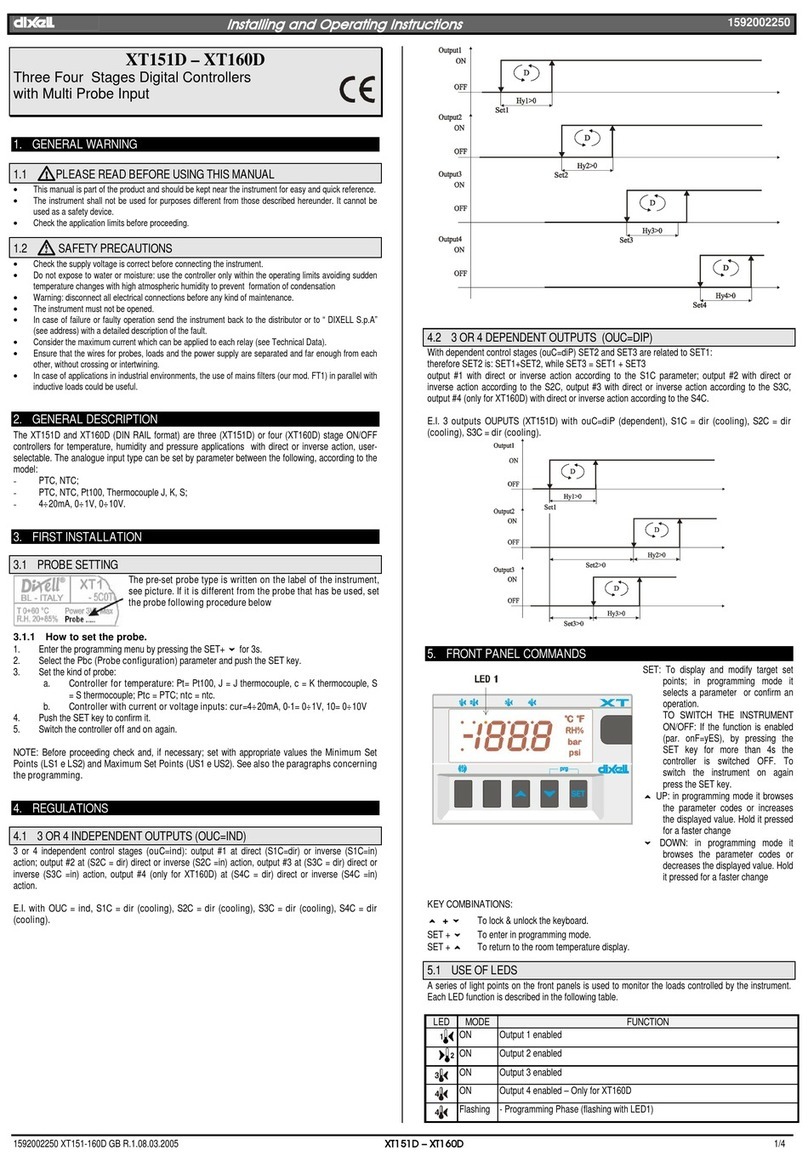
Programming Mode This screen enables the modification of the Set point or parameters.
Parameter Menu These screens enable the modification of all parameter values.
Set Point Menu This screen enables the modification of the Set Point value.
USER INTERACTION
HOME NAVIGATION PROG MENU ACTIVATION SET POINT MODIFICATION PROG MENU NAVIGATION
GESTURE HOW-TO DESCRIPTION
ONE TAP Press a specific area of the screen
with a finger for 1 sec
Switch ON / Switch OFF: when in Virtual Keyboard, use this to turn on/off a
specific function. When in Programming mode, use this to select a parameter or a
parameter value.
TAP and
HOLD Press any place of the screen with a
finger for 3 sec
Enter / Save: use this to enter Programming mode or Parameter menu and to
save modifications. When in Virtual Keyboard, use this on the “ONOFF” to switch
OFF and ON the device.
H-SWIPE Drag a finger across the screen, from
left to right or from right toleft
Browse: use horizontal swipe (right to left or left to right) to browse through
HOME, Virtual Keyboard and Info View. When in programming mode: use
horizontal swipe to browse through parameter menu.
V-SWIPE Drag a finger across the screen, from
top to bottom or from bottom to top
(overlapping only one of the digits)
Modify: use vertical swipe (from top to bottom or bottom to top) to change a
parameter value.
H-SWIPE TAP and HOLD TAP and HOLD on SET TAP and HOLD on PRG
H-SWIPE
1569005010 XR30-60-70T QRG EN r1.1 2020.06.05 XR30-60-70T 2/2
H-SWIPE
to browse
PROGRAMMING MENU
(…)
and iconsare blinking
TECHNICAL SPECIFICATIONS
FEATURES DESCRIPTION
Housing Self-extinguishing PC
Dimensions Front fascia 38x80 mm; case depth 81mm
Mounting device Panel, 71x29mm panel cut-out
Degree of Protection NEMA – UL 50e Indoor use only, Type 1 enclosure
IP-IEC/EN 60529 Front panel: IP66 Rear Housing: IP00
Power Supply 230Vac

10%, 50/60Hz; 110Vac

10%, 50/60Hz; 100 to 240VAC

10%, 50/60Hz
Overvoltage Category II
Rated Power 12VAC: 3VA; 110VAC: 4VA; 230VAC: 4VA; 100-240VAC: 3VA
FEATURES DESCRIPTION
Rated Impulse Voltage 2500V
Display White display, LED type, 3 digits with decimal point and multi-function icons
Buzzer Internal, always present
Software Class A
Terminal blocks / Terminal
Connections Plug-in or screw terminal block, wire section between 0,5 and 2,5 mm2
Max tightening force: 0.3 N/m for 3,5mm pitch, 0.4 N/m for 5,0mm pitch
Data Storing Real Time Clock: Data maintenance up to 6 months with lithium battery. Other parameters: internal flash.
Type of Action 1.B
Pollution Degree 2, non-condensing humidity
Ambient Operating
Temperature and Humidity IEC/EN 0T60°C; 20-85 rH% (non-condensing humidity)
UL-CAN/CSA -20T60°C; 20-85 rH% (non-condensing humidity)
Shipping and storage
temperature -40T85°C; 20-85 rH% (non-condensing humidity)
Resistance to Heat UL 94 V-0
Measurement range NTC: -40T110°C, resolution 0.1°C or 1°C (selectable); PT1000: -100T150°C, resolution 0.1°C or 1°C
(selectable); PTC: -50T150°C, resolution 0.1°C or 1°C (selectable)
Accuracy ±1% compared to the full scale
Inputs Up to 4 NTC, PTC or PT1000 (configurable); Up to 2 voltage free contacts
Relay Outputs
Nominal UL IEC
oA1 SPST 16A,
250Vac
Resistive load 12A (NO), 230Vac, 50K cycles
Motor load240Vac (NO), 10FLA/60LRA, 30K cycles
Pilot Duty B300 (NO), 6K cycles
10(4)A (NO), 230Vac, 100K
cycles
oA2 SPDT 8A,
250Vac
Resistive load 10A (NO), 120/240Vac, 30K cycles
Motor load½ HP (NO), 240Vac, 30K cycles
Motor load¼ HP (NO), 120Vac, 30K cycles
Pilot duty B300 (NO), 30K cycles
8(3)A (NO), 230Vac, 50K
cycles
oA3
(*) SPST 5A,
250Vac
Resistive load 5A, 120/240Vac, 50K cycles
Motor load240Vac, 1.9FLA/11.4LRA, 30K cycles
Pilot Duty B300, 30K cycles 5(1)A, 230Vac, 50K cycles
oA4
(**) SPST 8A,
250Vac
Resistive load 10A (NO), 120/240Vac, 30K cycles
Motor load½ HP (NO), 240Vac, 30K cycles
Motor load¼ HP (NO), 120Vac, 30K cycles
Pilot duty B300 (NO), 30K cycles
8(3)A (NO), 230Vac, 50K
cycles
Maximum ampacity on common
terminal “Line” (for oAx) 16A
I/O port HOT-KEY: MAX voltage allowed is 5 VDC. DO NOT CONNECT ANY EXTERNAL POWER SUPPLY.
Purpose of control Operating control
Construction of control Incorporated control, intended to be used in Class I or Class II equipment
Approvals
R290/R600a: relays tested according to IEC EN60079:0 and IEC EN60079:15
IEC/EN 60730-1; IEC/EN 60730-2-9
UL 60730-1; UL 60730-2-9
CAN/CSA E60730-1; CAN/CSA E60730-2-9
(*) XR60T and XR70T only
(**) XR70T only
TAP and HOLD
PRESS “PRG”
TAP and HOLD “PRG”
TAP and HOLD “PRG” to
save and exit
V-SWIPE
to modify
TAP and HOLD “PRG”
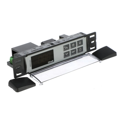
This manual suits for next models

2

Other dixell Controllers manuals

dixell XM440K Wiring diagram

dixell

dixell XM440K Wiring diagram

dixell T66 Wiring diagram

dixell

dixell T66 Wiring diagram

dixell XR70CX Instruction Manual

dixell

dixell XR70CX Instruction Manual

dixell iCHiLL 100CX User manual

dixell

dixell iCHiLL 100CX User manual

dixell XW60LS Wiring diagram

dixell

dixell XW60LS Wiring diagram

dixell XC660D Wiring diagram

dixell

dixell XC660D Wiring diagram

dixell XR20C Wiring diagram

dixell

dixell XR20C Wiring diagram

dixell XC642C User manual

dixell

dixell XC642C User manual

dixell XV110K User manual

dixell

dixell XV110K User manual

dixell XR40C Wiring diagram

dixell

dixell XR40C Wiring diagram

dixell XW30LS User manual

dixell

dixell XW30LS User manual

dixell xc440c User manual

dixell

dixell xc440c User manual

dixell XLR130 Instruction Manual

dixell

dixell XLR130 Instruction Manual

dixell XC706M User manual

dixell

dixell XC706M User manual

dixell XWA11V User manual

dixell

dixell XWA11V User manual

dixell iCHILL 100CX EVO User manual

dixell

dixell iCHILL 100CX EVO User manual

dixell CX620 Wiring diagram

dixell

dixell CX620 Wiring diagram

dixell Wing XW40L Instruction Manual

dixell

dixell Wing XW40L Instruction Manual

dixell ichill IC100C series User manual

dixell

dixell ichill IC100C series User manual

dixell XR72CX Wiring diagram

dixell

dixell XR72CX Wiring diagram

dixell XW35VS Wiring diagram

dixell

dixell XW35VS Wiring diagram

dixell XW60K Wiring diagram

dixell

dixell XW60K Wiring diagram

dixell XT151D Wiring diagram

dixell

dixell XT151D Wiring diagram

dixell WING XW272K Wiring diagram

dixell

dixell WING XW272K Wiring diagram

Popular Controllers manuals by other brands

Rhymebus RM5G manual

Rhymebus

Rhymebus RM5G manual

Grace m908 user manual

Grace

Grace m908 user manual

Mitsubishi MELSEC-F FX3U-2HC user manual

Mitsubishi

Mitsubishi MELSEC-F FX3U-2HC user manual

nekos SKY 650 instruction manual

nekos

nekos SKY 650 instruction manual

Integra DHC-80.1 instruction manual

Integra

Integra DHC-80.1 instruction manual

IBM FlashSystem 900 Service guide

IBM

IBM FlashSystem 900 Service guide

Siemens Flowrite 599 Series installation instructions

Siemens

Siemens Flowrite 599 Series installation instructions

A10 Harmony Controller 2000 quick start guide

A10

A10 Harmony Controller 2000 quick start guide

WEG PFW03-M08 user manual

WEG

WEG PFW03-M08 user manual

resideo VR8200A installation instructions

resideo

resideo VR8200A installation instructions

Adaptive AlphaVision III PC Series Replacement instructions

Adaptive

Adaptive AlphaVision III PC Series Replacement instructions

ACME Koolmaster PP-32 user manual

ACME

ACME Koolmaster PP-32 user manual

S&C Micro-AT Operation

S&C

S&C Micro-AT Operation

Johnson Controls M9206-DN Series installation instructions

Johnson Controls

Johnson Controls M9206-DN Series installation instructions

Nexigo NS32 user manual

Nexigo

Nexigo NS32 user manual

Parrot Cockpitglasses quick start guide

Parrot

Parrot Cockpitglasses quick start guide

PIETRO FIORENTINI APERVAL Use and maintenance manual

PIETRO FIORENTINI

PIETRO FIORENTINI APERVAL Use and maintenance manual

Aaeon AEC-6905 manual

Aaeon

Aaeon AEC-6905 manual

manuals.online logo
manuals.online logoBrands
  • About & Mission
  • Contact us
  • Privacy Policy
  • Terms and Conditions

Copyright 2025 Manuals.Online. All Rights Reserved.