manuals.online logo
Brands
  1. Home
  2. •
  3. Brands
  4. •
  5. Dixon
  6. •
  7. Industrial Equipment
  8. •
  9. Dixon 5500 Series Operating and maintenance manual

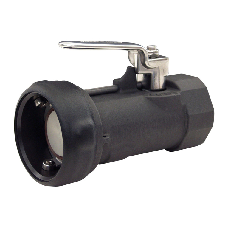
Dixon 5500 Series Operating and maintenance manual

090140 REV5 2021/12/15 877.582.3569 1
MAINTENANCE & OPERATING
INSTRUCTIONS
For
DIXON
5500 SERIES
API RACK COUPLER
For Sales & Service Contact
dixonvalve.com
USA:
Dixon Bayco USA
Chestertown, Maryland
Phone: 410-778-2000
Fax: 410-778-4702
Toll Free: 800-355-1991
E-mail: dixonbayco@dixonvalve.com
Canada:
Dixon Group Canada Limited
Mississauga, Ontario
Phone: 905-673-5999
Fax: 905-673-2454
Toll Free: 877-963-4966
E-mail: isales@dixongroupcanada.com
Mexico:
Dixva, S. de R.L. de C.V.
Monterrey, N.L
Phone: 01-800-00-DIXON (34966)
Fax: 01-81-8354-8197
E-mail: contactenos@dixonvalve.com.mx
Europe:
Dixon Group Europe Ltd
Preston, England
Phone: +44 (0)1772 323529
Fax: +44 (0)1772 314664
E-mail: enquiries@dixoneurope.co.uk
Asia Pacific:
Dixon (Asia Pacific) Pty Ltd
Wingfield, South Australia
Phone: +61 8 8202 6000
Fax: +61 8 8202 6099
E-mail: enquiries@dixonvalve.com.au
090140 REV5 2021/12/15 877.582.3569 2
5500 Series API Rack Coupler Model Numbers
5500G............ FKM GFLT SEALS, ALUMINUM HANDLE
5500B............ FKM B SEALS, ALUMINUM HANDLE
5500E ............ EPDM SEALS, ALUMINUM HANDLE
5500F............. FLUOROSILICONE SEALS, ALUMINUM HANDLE
5500BL.......... BAYLAST SEALS, ALUMINUM HANDLE
5500K............ FFKM SEALS, ALUMINUM HANDLE
5500H............ HIFLUOR SEALS, ALUMINUM HANDLE
5500G-L ........ FKM GFLT SEALS, ALUMINUM LOCKING HANDLE
5500B-L ........ FKM B SEALS, ALUMINUM LOCKING HANDLE
5500E-L......... EPDM SEALS, ALUMINUM LOCKING HANDLE
5500F-L......... FLUOROSILICONE SEALS, ALUMINUM LOCKING HANDLE
5500BL-L...... BAYLAST SEALS, ALUMINUM LOCKING HANDLE
5500K-L ........ FFKM SEALS, ALUMINUM LOCKING HANDLE
5500H-L ........ HIFLUOR SEALS, ALUMINUM LOCKING HANDLE
5500G-SS ...... FKM GFLT SEALS, STAINLESS STEEL HANDLE
5500B-SS....... FKM B SEALS, STAINLESS STEEL HANDLE
5500E-SS....... EPDM SEALS, STAINLESS STEEL HANDLE
5500F-SS....... FLUOROSILICONE SEALS, STAINLESS STEEL HANDLE
5500BL-SS.... BAYLAST SEALS, STAINLESS STEEL HANDLE
5500K-SS ...... FFKM SEALS, STAINLESS STEEL HANDLE
5500H-SS ...... HIFLUOR SEALS, STAINLESS STEEL HANDLE
5500G-SSL.... FKM GFLT SEALS, STAINLESS STEEL LOCKING HANDLE
5500B-SSL .... FKM B SEALS, STAINLESS STEEL LOCKING HANDLE
5500E-SSL .... EPDM SEALS, STAINLESS STEEL LOCKING HANDLE
5500F-SSL..... FLUOROSILICONE SEALS, STAINLESS STEEL LOCKING HANDLE
5500BL-SSL.. BAYLAST SEALS, STAINLESS STEEL LOCKING HANDLE
5500K-SSL.... FFKM SEALS, STAINLESS STEEL LOCKING HANDLE
5500H-SSL.... HIFLUOR SEALS, STAINLESS STEEL LOCKING HANDLE
5500G-SH...... FKM GFLT SEALS, SHORT ALUMINUM HANDLE
5500B-SH...... FKM B SEALS, SHORT ALUMINUM HANDLE
5500E-SH...... EPDM SEALS, SHORT ALUMINUM HANDLE
5500F-SH ...... FLUOROSILICONE SEALS, SHORT ALUMINUM HANDLE
5500BL-SH.... BAYLAST SEALS, SHORT ALUMINUM HANDLE
5500K-SH...... FFKM SEALS, SHORT ALUMINUM HANDLE
5500H-SH...... HIFLUOR SEALS, SHORT ALUMINUM HANDLE
090140 REV5 2021/12/15 877.582.3569 3
5500 SERIES API RACK COUPLER
Item
#
Description
Part #
5500B
5500E
5500F
5500G
5500BL
5500K
5500H
5500B-L
5500E-L
5500F-L
5500G-L
5500BL-L
5500K-L
5500H-L
5500B-SS
5500E-SS
5500F-SS
5500G-SS
5500BL-SS
5500K-SS
5500H-SS
5500B-SSL
5500E-SSL
5500F-SSL
5500G-SSL
5500BL-SSL
5500K-SSL
5500H-SSL
5500B-SH
5500E-SH
5500F-SH
5500G-SH
5500BL-SH
5500K-SH
5500H-SH
1
Body
341933
1
1
1
1
1
1
1
1
1
1
1
1
1
1
1
1
1
1
1
1
1
1
1
1
1
1
1
1
1
1
1
1
1
1
1
2
Shaft
391876
1
1
1
1
1
1
1
1
1
1
1
1
1
1
1
1
1
1
1
1
1
1
1
1
1
1
1
1
1
1
1
1
1
1
1
3
Cotter Pin
112307
1
1
1
1
1
1
1
1
1
1
1
1
1
1
1
1
1
1
1
1
1
1
1
1
1
1
1
1
1
1
1
1
1
1
1
4
Sleeve Assembly
400764
1
1
1
1
1
1
1
1
1
1
1
1
1
1
1
1
1
1
1
1
1
1
1
1
1
1
1
1
1
1
1
1
1
1
5
Valve Assembly
400739
1
1
1
1
1
1
1
1
1
1
1
1
1
1
1
1
1
1
1
1
1
1
1
1
1
1
1
1
1
1
1
1
1
1
1
6A
Nose Seal Assy -
FKM B
400741
1
-
-
-
-
-
-
1
-
-
-
-
-
-
1
-
-
-
-
-
-
1
-
-
-
-
-
-
1
-
-
-
-
-
-
6B
Nose Seal Assy -
EPDM
400745
-
1
-
-
-
-
-
-
1
-
-
-
-
-
-
1
-
-
-
-
-
-
1
-
-
-
-
-
-
1
-
-
-
-
-
6C
Nose Seal Assy -
F/SILICONE
400746
-
-
1
-
-
-
-
-
-
1
-
-
-
-
-
-
1
-
-
-
-
-
-
1
-
-
-
-
-
-
1
-
-
-
-
6D
Nose Seal Assy -
FKM GFLT
400742
-
-
-
1
-
-
-
-
-
-
1
-
-
-
-
-
-
1
-
-
-
-
-
-
1
-
-
-
-
-
-
1
-
-
-
6E
Nose Seal Assy -
BAYLAST
400743
-
-
-
-
1
-
-
-
-
-
-
1
-
-
-
-
-
-
1
-
-
-
-
-
-
1
-
-
-
-
-
-
1
-
-
6F
Nose Seal Assy -
FFKM
400767
-
-
-
-
-
1
-
-
-
-
-
-
1
-
-
-
-
-
-
1
-
-
-
-
-
-
1
-
-
-
-
-
-
1
-
6G
Nose Seal Assy -
HIFLUOR
400769
-
-
-
-
-
-
1
-
-
-
-
-
-
1
-
-
-
-
-
-
1
-
-
-
-
-
-
1
-
-
-
-
-
-
1
7A
Bearing Assembly -
FKM B
400747
1
-
-
-
-
-
-
1
-
-
-
-
-
-
1
-
-
-
-
-
-
1
-
-
-
-
-
-
1
-
-
-
-
-
-
7B
Bearing Assembly -
EPDM
400751
-
1
-
-
-
-
-
-
1
-
-
-
-
-
-
1
-
-
-
-
-
-
1
-
-
-
-
-
-
1
-
-
-
-
-
7C
Bearing Assembly -
F/SILICONE
400752
-
-
1
-
-
-
-
-
-
1
-
-
-
-
-
-
1
-
-
-
-
-
-
1
-
-
-
-
-
-
1
-
-
-
-
7D
Bearing Assembly -
FKM GFLT
400748
-
-
-
1
-
-
-
-
-
-
1
-
-
-
-
-
-
1
-
-
-
-
-
-
1
-
-
-
-
-
-
1
-
-
-
7E
Bearing Assembly -
BAYLAST
400749
-
-
-
-
1
-
-
-
-
-
-
1
-
-
-
-
-
-
1
-
-
-
-
-
-
1
-
-
-
-
-
-
1
-
-
7F
Bearing Assembly -
FFKM
400766
-
-
-
-
-
1
-
-
-
-
-
-
1
-
-
-
-
-
-
1
-
-
-
-
-
-
1
-
-
-
-
-
-
1
-
7G
Bearing Assembly -
HIFLUOR
400770
-
-
-
-
-
-
1
-
-
-
-
-
-
1
-
-
-
-
-
-
1
-
-
-
-
-
-
1
-
-
-
-
-
-
1
8
Bearing Washer
112601
1
1
1
1
1
1
1
1
1
1
1
1
1
1
1
1
1
1
1
1
1
1
1
1
1
1
1
1
1
1
1
1
1
1
1
9
Locking Plate
112589
1
1
1
1
1
1
1
1
1
1
1
1
1
1
1
1
1
1
1
1
1
1
1
1
1
1
1
1
1
1
1
1
1
1
1
10A
Handle
341937
1
1
1
1
1
1
1
-
-
-
-
-
-
-
-
-
-
-
-
-
-
-
-
-
-
-
-
-
-
-
-
-
-
-
1
10B
Handle Lockable
Assy
400740
-
-
-
-
-
-
-
1
1
1
1
1
1
1
-
-
-
-
-
-
-
-
-
-
-
-
-
-
-
-
-
-
-
-
-
10C
Stainless Steel
Handle
112627
-
-
-
-
-
-
-
-
-
-
-
-
-
-
1
1
1
1
1
1
1
-
-
-
-
-
-
-
-
-
-
-
-
-
-
10D
Handle SS lockable
Assy
400765
-
-
-
-
-
-
-
-
-
-
-
-
-
-
-
-
-
-
-
-
-
1
1
1
1
1
1
1
-
-
-
-
-
-
-
10E
Short Handle
341941
-
-
-
-
-
-
-
-
-
-
-
-
-
-
-
-
-
-
-
-
-
-
-
-
-
-
-
-
1
1
1
1
1
1
1
11
Spacer
391142
1
1
1
1
1
1
1
1
1
1
1
1
1
1
1
1
1
1
1
1
1
1
1
1
1
1
1
1
1
1
1
1
1
1
1
12
Cotter Pin
111563
2
2
2
2
2
2
2
2
2
2
2
2
2
2
2
2
2
2
2
2
2
2
2
2
2
2
2
2
2
2
2
2
2
2
2
13
Interlocking Cam
112147
5
5
5
5
5
5
5
5
5
5
5
5
5
5
5
5
5
5
5
5
5
5
5
5
5
5
5
5
5
5
5
5
5
5
5
14
Torsion Spring
112149
6
6
6
6
6
6
6
6
6
6
6
6
6
6
6
6
6
6
6
6
6
6
6
6
6
6
6
6
6
6
6
6
6
6
6
15
Latch
112240
1
1
1
1
1
1
1
1
1
1
1
1
1
1
1
1
1
1
1
1
1
1
1
1
1
1
1
1
1
1
1
1
1
1
1
16
Release
391875
1
1
1
1
1
1
1
1
1
1
1
1
1
1
1
1
1
1
1
1
1
1
1
1
1
1
1
1
1
1
1
1
1
1
1
17
Release Washer
112602
2
2
2
2
2
2
2
2
2
2
2
2
2
2
2
2
2
2
2
2
2
2
2
2
2
2
2
2
2
2
2
2
2
2
2
18
Bail
341935
1
1
1
1
1
1
1
1
1
1
1
1
1
1
1
1
1
1
1
1
1
1
1
1
1
1
1
1
1
1
1
1
1
1
1
19
Bail Pin
112619
2
2
2
2
2
2
2
2
2
2
2
2
2
2
2
2
2
2
2
2
2
2
2
2
2
2
2
2
2
2
2
2
2
2
2
20
Bail Spring
112150
2
2
2
2
2
2
2
2
2
2
2
2
2
2
2
2
2
2
2
2
2
2
2
2
2
2
2
2
2
2
2
2
2
2
2
21
Shoulder Screw
112621
1
1
1
1
1
1
1
1
1
1
1
1
1
1
1
1
1
1
1
1
1
1
1
1
1
1
1
1
1
1
1
1
1
1
1
22
Lock Nut
112620
1
1
1
1
1
1
1
1
1
1
1
1
1
1
1
1
1
1
1
1
1
1
1
1
1
1
1
1
1
1
1
1
1
1
1
23
Comp. Spring
112617
1
0
1
0
1
0
1
0
1
0
1
0
1
0
1
0
1
0
1
0
1
0
1
0
1
0
1
0
1
0
1
0
1
0
1
0
1
0
1
0
1
0
1
0
1
0
1
0
1
0
1
0
1
0
1
0
1
0
1
0
1
0
1
0
1
0
1
0
1
0
24
Set Screw
112622
2
2
2
2
2
2
2
2
2
2
2
2
2
2
2
2
2
2
2
2
2
2
2
2
2
2
2
2
2
2
2
2
2
2
2
25
Dust Ring
112173
1
1
1
1
1
1
1
1
1
1
1
1
1
1
1
1
1
1
1
1
1
1
1
1
1
1
1
1
1
1
1
1
1
1
1
26
Sleeve Lock
112625
1
1
1
1
1
1
1
1
1
1
1
1
1
1
1
1
1
1
1
1
1
1
1
1
1
1
1
1
1
1
1
1
1
1
1
27
Shoulder Screw
112626
1
1
1
1
1
1
1
1
1
1
1
1
1
1
1
1
1
1
1
1
1
1
1
1
1
1
1
1
1
1
1
1
1
1
1
28A
O-Ring 208, FKM B
112603
1
-
-
-
-
-
-
1
-
-
-
-
-
-
1
-
-
-
-
-
-
1
-
-
-
-
-
-
1
-
-
-
-
-
-
28B
O-Ring 208, EPDM
112611
-
1
-
-
-
-
-
-
1
-
-
-
-
-
-
1
-
-
-
-
-
-
1
-
-
-
-
-
-
1
-
-
-
-
-
28C
O-Ring 208,
F/SILICONE
112613
-
-
1
-
-
-
-
-
-
1
-
-
-
-
-
-
1
-
-
-
-
-
-
1
-
-
-
-
-
-
1
-
-
-
-
28D
O-Ring 208, FKM
GFLT
112605
-
-
-
1
-
-
-
-
-
-
1
-
-
-
-
-
-
1
-
-
-
-
-
-
1
-
-
-
-
-
-
1
-
-
-
28E
O-Ring 208,
BAYLAST
112607
-
-
-
-
1
-
-
-
-
-
-
1
-
-
-
-
-
-
1
-
-
-
-
-
-
1
-
-
-
-
-
-
1
-
-
28F
O-Ring 208, FFKM
112643
-
-
-
-
-
1
-
-
-
-
-
-
1
-
-
-
-
-
-
1
-
-
-
-
-
-
1
-
-
-
-
-
-
1
-
28G
O-Ring 208, HIFLUOR
112653
-
-
-
-
-
-
1
-
-
-
-
-
-
1
-
-
-
-
-
-
1
-
-
-
-
-
-
1
-
-
-
-
-
-
1
29
INSIDE SHAFT
WASHER
112159
1
1
1
1
1
1
1
1
1
1
1
1
1
1
1
1
1
1
1
1
1
1
1
1
1
1
1
1
1
1
1
1
1
1
1
090140 REV5 2021/12/15 877.582.3569 4
API RACK COUPLER –5500 SERIES
090140 REV5 2021/12/15 877.582.3569 5
5500 Series API Rack coupler Sub-assembly Components
*Items are optional PTFE U seals. When the U seals are added to the coupler, they isolate the main rubber seals from the liquid being
conveyed, thereby increasing the longevity of the rubber seals. Contact Dixon for kit numbers.
Item #
Description
Part #
Q’ty
4
Sleeve Assembly
400764
-
4.1
Sleeve
-
1
4.2
Sleeve Insert
-
1
4.3
Sleeve Pin
-
3
4.4
Grip Nail
-
2
4.5
Tag
-
1
5
Valve Assembly
400739
-
5.1
Poppet
341934
1
5.2
Bend Link
112151
2
5.3
Bend Link Pin
391141
2
5.4
Washer
112602
2
5.5
Cotter Pin
110721
2
5.6
Drive Link
112148
1
6
Nose Seal Assy
See Dixon website for kit
numbers
-
6.1
Nose Piece
391877
1
6.2
O-Ring 349
See Dixon website for kit
numbers
1
6.3
Nose Seal
See Dixon website for kit
numbers
1
6.4
Dust Felt Ring
112174
1
6.5*
U-Seal 349
See Dixon website for kit
numbers
1
7
Bearing Assembly
See Dixon website for kit
numbers
-
7.1
Bearing
341936
1
7.2
O-Ring 208
See Dixon website for kit
numbers
1
7.3
O-Ring 216
See Dixon website for kit
numbers
2
7.4*
U-Seal 208
See Dixon website for kit
numbers
1
7.5*
U-Seal 216
See Dixon website for kit
numbers
1
090140 REV5 2021/12/15 877.582.3569 6
090140 REV5 2021/12/15 877.582.3569 7
These instructions and recommendations are provided to ensure proper operation and long service
life of the Dixon 5500 API rack coupler. Parts are identified by the item numbers on the assembly
drawing and part list.
SUGGUESTED MAINTENANCE SCHEDULE:
1. MONTHLY INSPECTION
Visual inspection of the API rack coupler operation can be done while the API rack coupler is still
on the loading arm. All safety precautions that apply to the use of the API rack coupler must be
followed.
While the API rack coupler is still on the loading arm, visually examine the API rack coupler for any
worn or damaged parts, such as the body (1), sleeve (4), handle (10), bail (18), poppet (5.1), nose
seal (6.3), interlocking cams (13), latch (15), flange bolts, etc, or any other condition that may affect
the operation of the API rack coupler.
Examine the API rack coupler to make sure that the API rack coupler functions well. See Clause 3
in Section “INSTALL API RACK COUPLER TO LOADING ARM” for procedures.
Check the handle (10) for free and easy movement of the opening and closing cycle. Operation of
the handle (10) normally requires limited effort. If operating the handle (10) involves stronger force,
it implies the need to clean and possibly replace the shaft bearing (7) and the shaft (2).
During service time when the line is filled with liquid product, visually check for evidence of
leakage, especially through the shaft seals (7.2, 7.3, 7.4, 7.5 and 28), nose piece seals (6.2, 6.5),
nose seal (6.3) and the flange gasket. Any evidence of leakage means there is a need for further
maintenance.
2. YEARLY INSPECTION
For yearly inspection, the API rack coupler should be removed from the loading arm. See Section
“DISMANTLE API RACK COUPLER FROM LOADING ARM”for procedures of how to dismantle
the API rack coupler from the loading arm. See Section “DISASSEMBLY” for procedures of how to
disassemble the API rack coupler for further maintenance.
It is recommended that all seals (6.2, 6.3, 6.5, 7.2, 7.3, 7.4,7.5 and 28) should be inspected every
12 months. Replace any worn or damaged seals. See Section “REPLACE SEALS” for
procedures.
It is recommended that the valve assembly should be inspected every 12 months. Check the bent
links (5.2), and poppet (5.1) carefully to make sure that there is no permanent deformation, wear,
cracking, or any other damage. Check the bent link pins (5.3) carefully to make sure there is no
permanent deformation such as bending and cracking. Replace any deformed, worn or damaged
parts in the valve assembly. See Section “REPLACE VALVE ASSEMBLY AND PARTS”for
procedures.
Warning: Deformed bent link pins (5.3), drive link (5.6) and bent links (5.2) may cause leakage
through poppet seals. Further service will lead to cracks and breakage, which will cause a
complete failure of the API rack coupler.
Visually examine the shaft (2) every 12 months for significant dirt accumulation that could cause
shaft seal leakage. Visually examine the shaft (2), bearing washer (8), handle (10) and shoulder
screw (21) for wear and damage. Replace any worn or damaged parts.
090140 REV5 2021/12/15 877.582.3569 8
Warning: If the shoulder screws (21 and 27) break, this can cause the poppet to be left in partially
open position which may cause spill. Replace the shoulder screws (21 and 27) when they show
sign of wear or damage.
Visually examine the nose piece assembly every 12 months for significant dirt accumulation that
could cause nose piece seal leakage.
Visually examine the body (1), sleeve (4), interlocking cams (13), latch (15) and torsion springs
(14) for wear or damage every 12 months. Check the interlocking cam groove on the sleeve (4) for
wear and damage. Replace any worn or damaged parts.
Warning: If there is significant wear on the interlocking cam groove of the sleeve (4) or the
interlocking cams (13), replace the sleeve (4) or interlocking cams (13) immediately. Failure to
replace these parts can cause failure to interlock the API rack coupler.
3. SEAL REPLACEMENT
It is recommended that seals should be replaced with appropriate API rack coupler seal kit every 2
years, or at the first evidence of leakage. See Section “REPLACE SEALS” for procedures.
4. OVERHAUL
It is recommended that a complete overhaul of the API rack coupler should be performed every 4
years, or at the first evidence of leakage. Complete overhaul would involve seal inspection and
replacement, valve assembly inspection, inspection of body (1), sleeve (4), shaft (2), interlocking
cams (13), latch (15) and springs (14, 20). Replace any worn or damaged parts immediately. See
corresponding sections for procedures.
CAUTION! WHEN THE API RACK COUPLER POPPET (5.1) IS UNDER PRESSURE, THE
HANDLE (10) OF THE API RACK COUPLER MAY ROTATE VIOLENTLY.
PERSONAL INJURIES MAY RESULT IF THIS PRECAUTION IS NOT TAKEN.
INSTALL API RACK COUPLER TO LOADING ARM:
Warning: Read and understand this instruction manual before starting installation.
1. Check the API rack coupler to make sure that there is no damage.
2. Secure the loading arm. Align the TTMA 4” flange of the API rack coupler to the loading arm
end flange with TTMA 4” gasket. Insert two bolts into the top bolt holes on the flanges and
hand tighten the bolts first. Install the remaining six bolts and tighten all the bolts.
3. Make sure that all other devices for the loading arm are properly installed and ready for use.
Make sure that there is no liquid product in the line. Snap the API rack coupler onto an API
adapter. Check the followings:
•Make sure that the nose ring of API adapter is locked by the five interlocking cams (13) of
the API rack coupler.
•Make sure that the sleeve (4) moves fully forward to the outlet of the API rack coupler.
•If the sleeve (4) is in place, check the interlock by pulling back the API rack coupler or
bending the API rack coupler sideways without triggering the release (16). The API rack
coupler should be locked tightly.
•If the API rack coupler is locked tightly, fully rotate the handle (10) to the open position.
Make sure that the handle (10) can rotate freely and the poppet (5.1) of the API rack
coupler can push the poppet of the API adapter to the open position.
090140 REV5 2021/12/15 877.582.3569 9
•When the poppet (5.1) of the API rack coupler is in the open position, try to trigger the
release (16) to make sure that the sleeve (4) is locked by the interlocking cam surface of
the handle (10).
•Rotate the handle (10) to fully closed position. Trigger the release (16). The sleeve (4)
should move back and five interlocking cams (13) should unlock the nose ring of the API
adapter. The API rack coupler should be able to be removed from the API adapter.
•If there are problems with any of the above, see the following section to dismantle the API
rack coupler from the API adapter and remove the API rack coupler from the loading arm.
See Section “DISASSEMBLY”for further instructions of how to disassemble the API rack
coupler to inspect individual parts. Contact the factory if it is a new API rack coupler.
DISMANTLE API RACK COUPLER FROM LOADING ARM:
Warning: Read and understand this instruction manual before starting installation. Make sure that
there is adequate personal protection all the time when dismantling the API rack coupler from the
loading arm.
1. Shut off all working devices. Drain the loading arm. Dismantle the API rack coupler when it
is clean and dry.
2. Secure the loading arm from movement and support the API rack coupler. Make sure that
the API rack coupler is fully closed.
3. Loosen the bolts on the TTMA flange of the API rack coupler. Leave the two top bolts on
and remove the remaining six bolts first. And then remove the two top bolts.
4. Remove the API rack coupler from the loading arm. Remove the TTMA gasket between the
flanges.
REPLACE VALVE ASSEMBLY AND PARTS:
Note: Valve assembly (5) and parts can only be replaced when the API rack coupler is off the rack.
The design of the Dixon API rack coupler shaft (2) makes it easy to remove the valve assembly
from the API rack coupler as a whole. This makes it easy to replace the whole valve assembly (5)
or any individual part of the valve assembly (5). There is NO need to remove the bent link pins (5.3)
from the bent links (5.2) while the valve assembly is still in the API rack coupler.
Warning: Carefully handle the poppet (5.1) without damaging the sealing surface when replacing
valve assembly or parts. Even the smallest scratches on the sealing surface can cause leakage.
1. When the API rack coupler is off the rack, DO NOT remove the handle shoulder screw (21)
and lock nut (22) from the handle (10) yet same as the shoulder screw (27) and lock nut of
sleeve lock (26). When API rack coupler is closed, remove the shaft cotter pin (3) from the
shaft (2) by using pliers.
2. Defeat the interlock manually or use an API adapter nose ring so the sleeve (4) can move
fully forward to the outlet of the API rack coupler.
3. Turn the handle (10) to open the API rack coupler.
4. Pull out the shaft and handle assembly with locking plate (9), dust O-ring (28), bearing
assembly (7), bearing washer (8), while inside shaft washer (29), valve assembly (5) and
spacer (11) will fall free of the shaft (2).
5. Inspect all parts of the valve assembly (5) and replace any damaged parts. When
reassembling the valve assembly, make sure the bent links (5.2) and the drive link (5.6) are
assembled in the same orientation as shown in the valve assembly figure.
6. Assemble the shaft and handle assembly with sleeve lock (26), locking plate (9), dust O-ring
(28), bearing assembly (7) and bearing washer (8) to the body (1). Assemble the inside
shaft washer (29), drive link (5.6) and the spacer (11) before pushing the other end of the
090140 REV5 2021/12/15 877.582.3569 10
shaft (2) into the shaft end pocket on the body (1). Pay attention to the orientation of the
valve assembly.
7. Rotate the handle (10) to fully closed position. Install the shaft cotter pin (3) onto the shaft (2).
8. Check the API rack coupler with an API adapter to make sure all components are
assembled properly.
REPLACE SEALS:
Warning: Carefully remove and install parts without damaging any sealing surfaces when
replacing seals. Even the smallest scratches on the O-Ring groove or other sealing surface will
cause leakage.
REPLACE SHAFT SEALS IN STUFFING BOX
Note: While the API rack coupler is off the rack, shaft seals (7.2, 7.3, 7.4, 7.5 and 28) can be
replaced using the method described here.
1. Follow Step 1 to 4 from “REPLACE VALVE ASSEMBLY AND PARTS”.
2. To remove bearing assembly (7), unscrew the lock nuts (22) and remove the shoulder screw
(21) from the handle (10) and shoulder screw (27) from the sleeve lock (26). Remove the
handle (10) from the shaft (2) followed by the sleeve lock (26), locking plate (9), dust O-ring
(28), the bearing assembly (7) and bearing washer (8).
3. Remove the O-rings (7.2, 7.3) and the u-seals (7.4, 7.5, optional) from the bearing assembly
and make sure not to damage the bearing (7.1) or scratch sealing surfaces.
•If the bearing (7.1) is good, thoroughly clean the bearing (7.1) to remove any debris, oil
and grease. Lubricate NEW O-Rings (7.2 for inside groove and 7.3 for outside groove)
and install into the grooves. If u-seals (7.4, 7.5) are ordered, lubricate NEW u-seals (7.4
for inside groove and 7.5 for outside groove) and install into the grooves. Handle the u-
seals (7.4, 7.5) carefully and make sure not to damage.
•If the bearing (7.1) is already damaged or has scratches on the sealing surfaces, replace
the bearing assembly with a NEW bearing assembly, which includes the bearing (7.1),
the inside O-Ring (7.2), the outside O-Ring (7.3), the inside u-seal (7.4, optional) and the
outside u-seal (7.5, optional).
4. Install bearing washer (8) into the shaft (2) followed by the bearing assembly (7) and dust O-
ring (28) make sure it is greased, locking plate (9), sleeve lock (26) and then the handle
(10). Align the sleeve lock (26) and handle (10) to the shaft (2) holes and insert the shoulder
screws (21 & 27) then tighten the lock nuts (22).
5. Push the end of the shaft to the body through the inside shaft washer (29), drive link (5.6)
and spacer (11). At this instance the bearing assembly is also getting in to the stuffing box of
the body. Push the shaft assemble shaft (2) end to the shaft pocket on the body (1). Pay
attention to the orientation of the valve assembly.
6. Rotate the handle (10) to fully closed position. Install the shaft cotter pin (3) onto the shaft (2).
7. Check the API rack coupler with an API adapter to make sure all components are
assembled properly.
REPLACE THE SEALS ON THE NOSE PIECE
Note: Nose piece seals, including O-Ring (6.2), nose piece dust ring (6.4) and optional u-seal (6.5),
can only be replaced when the API rack coupler is off the rack.
1. Follow Step 1 to 4 from “REPLACE VALVE ASSEMBLY AND PARTS”.
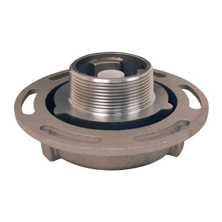
2. Remove the nose piece assembly, which includes the nose piece (6.1), nose seal (6.3), O-
Ring (6.2), nose piece dust ring (6.4), u-seal (6.5, optional). Remove and clean the
compression springs (23).
090140 REV5 2021/12/15 877.582.3569 11
•Remove nose seal (6.3), O-Ring (6.2), nose piece dust ring (6.4) and u-seal (6.5, if
applicable) from the nose piece (6.1).
•Inspect the nose piece (6.1) and make sure it is not damaged. Clean seal surfaces
carefully.
•Replace nose seal (6.3), O-Ring (6.2), nose piece dust ring (6.4) and u-seal (6.5, if
applicable) with new ones.
3. Assemble the compression spring (23) and nose piece assembly (6) to the body (1).
4. Follow step 5 to 7 from “REPLACE SHAFT SEALS IN STUFFING BOX”.
DISASSEMBLY:
Warning: Carefully remove parts without damaging any sealing surfaces when disassembling the
API rack coupler. Even the smallest scratches on the O-Ring grooves or other sealing surfaces will
cause leakage.
1. When the API rack coupler is closed, remove the shaft cotter pin (3) from the shaft (2) by
using pliers.
2. Defeat the interlock manually or use an API adapter nose ring so the sleeve (4) can move
fully forward to the outlet of the API rack coupler.
3. Turn the handle (10) to fully open position. Pull out the shaft and handle assembly with
locking plate (9), dust O-ring (28), bearing assembly (7) and bearing washer (8) while the
inside shaft washer (29), valve assembly (5) and spacer (11) will fall free of the shaft (2).
4. To completely disassemble the shaft and handle assembly, remove the handle lock nuts
(22) and shoulder screws (21 & 27). Remove the handle (10), sleeve lock (26), locking plate
(9), dust O-ring (28), bearing assembly (7) and bearing washer (8).
5. To completely disassemble the valve assembly, remove the bent link cotter pins (5.5), bent
link washers (5.4), and bent link pins (5.3).
6. To completely disassemble the bearing assembly, remove O-Rings (7.2, 7.3) and u-seals
(7.4, 7.5, optional) from the bearing (7.1).
7. Remove cotter pins (12) and washers (17) from the release (16) ends. Remove the release
(16) from the bail (18).
8. Remove the set screws (24) from the body (1) to remove the bail pins (19).
9. Turn the API rack coupler upside down and the bail pins (19) will fall out. If the bail pins (19)
do not fall out, move the bail springs (20) until the bail pins (19) fall out.
10.Remove the bail springs (20) and the bail (18).
11.Remove the sleeve (4) from the body (1) by pulling the sleeve (4) to the inlet of the body (1).
12.Remove the five interlocking cams (13) and latch (15) from the body (1). Remove the six
torsion springs (14) and dust ring (25) from the body (1).
13.Remove the nose piece assembly (6) and ten compression springs (23) from the body (1).
14.To completely disassemble the nose piece assembly, remove the O-Ring (6.2), nose piece
(6.1), nose piece dust ring (6.4), nose seal (6.3) and u-seal (6.5, optional) from the nose
piece (6.1).
ASSEMBLY:
Note: Remove any burrs and sharp edges that could damage the seals during reassembly.
1. Assemble the bearing assembly if it is disassembled. See Step 4 “Replace shaft seals
in stuffing box for procedures of how to assemble the bearing assembly.
2. Assemble the valve assembly if it is disassembled. See Section “REPLACE VALVE
ASSEMBLY AND PARTS”for procedures of how to assemble the valve assembly.
3. Assemble the nose piece assembly if it is disassembled. See Section “Replace the
seals on the nose piece”for procedures of how to assemble the nose piece assembly.
090140 REV5 2021/12/15 877.582.3569 12
4. Assemble the shaft and handle assembly if it is disassembled. Install bearing washer (8)
into the shaft (2) followed by the bearing assembly (7, make sure it is greased), dust O-
ring (28), locking plate (9), sleeve lock (26) and then the handle (10). Align the handle
(10) and sleeve lock (26) to the shaft (2) holes and insert the shoulder screws (21 and
27) then tighten the lock nuts (22).
5. Install the body dust ring (25) to the body dust groove.
6. Install the torsion springs (14), the latch (15) and the interlocking cams (13) to the body
(1).
7. Install the compression springs (23) and the nose piece assembly to the body (1).
8. Install the sleeve (4) to the body (1). Push in the five interlocking cams (13) manually so
the sleeve (4) can move fully forward to the outlet of the API rack coupler. Use nose ring
of API adapter or ask others for assistance.
9. Install the shaft and handle assembly with locking plate (9), dust O-ring (28), bearing
assembly (7) and bearing washer (8) to the body (1). Assemble the inside shaft washer
(29), drive link (5.6) of the valve assembly and the spacer (11) before pushing the other
end of the shaft (2) into the shaft pocket on the body (1). Pay attention to the orientation
of the valve assembly.
10.Rotate the handle (2) to fully closed position. Install the shaft cotter pin (3) onto the shaft
(2).
11.Install the bail (18), bail springs (20), bail pins (19) and tighten the set screws (24) to the
body (1).
12.Install the release (16) to the bail (18). Install the washers (17) and cotter pins (12) to the
ends of release (16).
13.Rotate the handle (10) to the open position and closed position several times to verify
proper operation.
14.When the handle (10) is in the closed position, trigger the release (16) so the sleeve (4)
can move fully backward to lock the handle (10). The API rack coupler should not be
able to be opened by rotating the handle (10).
15.Check the API rack coupler with an API adapter to make sure all components are
assembled properly.
Warning: If the sleeve subassembly (4) and interlocking cams (13) are disassembled
and replaced, try coupling and uncoupling the API rack coupler to an API adapter nose
ring a few times making sure the locking mechanism functions well before putting the
API rack coupler back onto the loading arm.
DIXON WARRANTY:
For Warranty Information, please refer to the inside back cover of the latest Dixon
Catalogue.

Other Dixon Industrial Equipment manuals

Dixon Bayco DBC Series Operating and maintenance manual

Dixon

Dixon Bayco DBC Series Operating and maintenance manual

Dixon 200-PV-9 Operating and maintenance manual

Dixon

Dixon 200-PV-9 Operating and maintenance manual

Dixon 6000EXT Manual

Dixon

Dixon 6000EXT Manual

Dixon Holedall 25 Ton Ram User manual

Dixon

Dixon Holedall 25 Ton Ram User manual

Dixon BAYCO 5300 Series Operating and maintenance manual

Dixon

Dixon BAYCO 5300 Series Operating and maintenance manual

Dixon A540 Series Operating and maintenance manual

Dixon

Dixon A540 Series Operating and maintenance manual

Dixon BAYCO 6000 Manual

Dixon

Dixon BAYCO 6000 Manual

Dixon Bayco Operating and maintenance manual

Dixon

Dixon Bayco Operating and maintenance manual

Dixon LGH5000 Series Operating and maintenance manual

Dixon

Dixon LGH5000 Series Operating and maintenance manual

Dixon VR6500 Manual

Dixon

Dixon VR6500 Manual

Dixon BAYCO BC Series Technical specifications

Dixon

Dixon BAYCO BC Series Technical specifications

Dixon SJSS Series User manual

Dixon

Dixon SJSS Series User manual

Dixon BAYCO PC5000 Manual

Dixon

Dixon BAYCO PC5000 Manual

Dixon BAYCO 6400 Manual

Dixon

Dixon BAYCO 6400 Manual

Dixon 6200X Manual

Dixon

Dixon 6200X Manual

Dixon SWMF125 Manual

Dixon

Dixon SWMF125 Manual

Dixon Bayco VR4040CS-ALS45 Operating and maintenance manual

Dixon

Dixon Bayco VR4040CS-ALS45 Operating and maintenance manual

Dixon VR4040CS-AL Operating and maintenance manual

Dixon

Dixon VR4040CS-AL Operating and maintenance manual

Popular Industrial Equipment manuals by other brands

ABB HT570801 Operation manual

ABB

ABB HT570801 Operation manual

Siemens LITHOSTAR Multiline Troubleshooting instructions

Siemens

Siemens LITHOSTAR Multiline Troubleshooting instructions

SCHUNK ELM Series Assembly and operating manual

SCHUNK

SCHUNK ELM Series Assembly and operating manual

Komfovent PPU-LCHX manual

Komfovent

Komfovent PPU-LCHX manual

Techne IFB-121 Operator's manual

Techne

Techne IFB-121 Operator's manual

Ilsintech SWIFT F1 Quick reference guide

Ilsintech

Ilsintech SWIFT F1 Quick reference guide

ABB HT614584 Operation manual

ABB

ABB HT614584 Operation manual

ABB A135-M66l HT612192 Operation manual

ABB

ABB A135-M66l HT612192 Operation manual

Vynckier CAT030S manual

Vynckier

Vynckier CAT030S manual

Hoval RoofVent RP operating instructions

Hoval

Hoval RoofVent RP operating instructions

Siemens 5WG1 262-1EB11 Operating and mounting instructions

Siemens

Siemens 5WG1 262-1EB11 Operating and mounting instructions

Siemens SIPROTEC 5 Compact Hardware description

Siemens

Siemens SIPROTEC 5 Compact Hardware description

ABB HT847020 Operation manual

ABB

ABB HT847020 Operation manual

ABB HT612326 Operation manual

ABB

ABB HT612326 Operation manual

TRAK VMC5 Safety, Installation, Maintenance, Service and Parts List

TRAK

TRAK VMC5 Safety, Installation, Maintenance, Service and Parts List

optris BR 20AR Operator's manual

optris

optris BR 20AR Operator's manual

ITW Gema EASY 1-L Operating instructions and spare parts list

ITW Gema

ITW Gema EASY 1-L Operating instructions and spare parts list

NCR 7350-K160 Kit instructions

NCR

NCR 7350-K160 Kit instructions

manuals.online logo
manuals.online logoBrands
  • About & Mission
  • Contact us
  • Privacy Policy
  • Terms and Conditions

Copyright 2025 Manuals.Online. All Rights Reserved.