dji Phantom 2 Vision + User manual

V1.4
2014.08
User Manual
PHANTOM 2 VISION+

2
©2014 DJI. All Rights Reserved.
Phantom 2 Vision +User Manual
2014.08
Please read this manual carefully before using the product.
Using This Manual
Key
Warning Important Hints and Tips References or Denitions
Important
Except when specically stated, all descriptions in this manual are for Phantom mode, not Naza-M mode.
Before Flight
The following tutorials and manuals have been produced to ensure you to make full use of your Phantom 2 Vision+.
(1) Disclaimer
(2) Phantom 2 Vision+ Quick Start Guide
(3) Phantom 2 Vision+ User Manual
(4) Phantom Pilot Training Guide
Watching all the tutorial videos and reading the Disclaimer before ight is recommended. Afterwards, prepare your rst
ight using the Phantom 2 Vision+ Quick Start Guide. Improve your ying skills in subsequent ights using the Phantom
Pilot Training Guide. Refer to this manual for more comprehensive information. Experienced users, particularly those with
DJI Phantom 2 Vision experience should skip to the Phantom 2 Vision+ Quick Start Guide to begin preparing for ight.
Watch the Tutorial Videos
Please watch the tutorial videos below to learn how to use Phantom 2 Vision+
correctly and safely.
http://www.dji.com/phantom2visionplus/training/
Phantom 2 Vision+ ofcial tutorial videos
Download DJI VISION App
Download and install the DJI VISION App. Choose one of the download methods below.
Search "DJI VISION" on the App Store then follow instructions for iOS version.
Search "DJI VISION" on Google Play then follow instructions for Android version.
Important Safety Notice
Use your Phantom carefully. It contains sensitive electronic components and may be damaged when dropped, crashed
or exposed to water. Never y a damaged Phantom.
Maintenance
Do not open or attempt to repair Phantom by yourself as doing so may cause damage to the Phantom or cause injury. If
the Phantom is not operating normally or has come into contact with liquid, contact a DJI authorized dealer or DJI customer
service. Learn more at www.dji.com/support
Battery
Never disassemble, pinch, crush, burn, drop or tread on the DJI smart ight battery. Never short or allow the metal contacts
on the battery terminal to touch. Do not expose batteries to extreme temperatures. Always use the DJI approved charger to
charge the battery. Keep the DJI battery away from children and store it in a cool, dry place.
Please read the Disclaimer before using your Phantom 2 Vision+.
iOS6.1 or above Android 4.0 or above
V1.4

©2014 DJI. All Rights Reserved.
3
Important Safety Notice 2
Using This Manual
Key 2
Important 2
Before Flight 2
Watch the Tutorial Videos 2
Download DJI VISION App 2
Overview
1 In the Box 5
2 Introduction 6
Assembly and Use
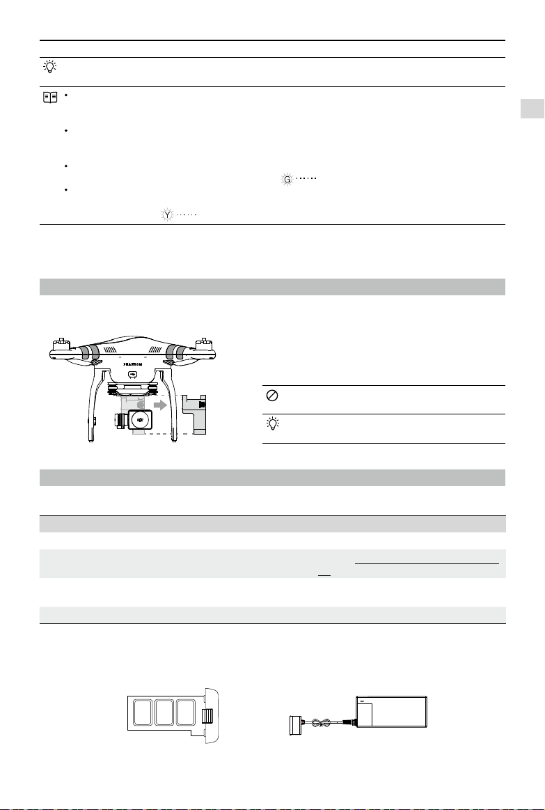
1 Removing Gimbal Clamp 7
2 Preparing the Battery 7
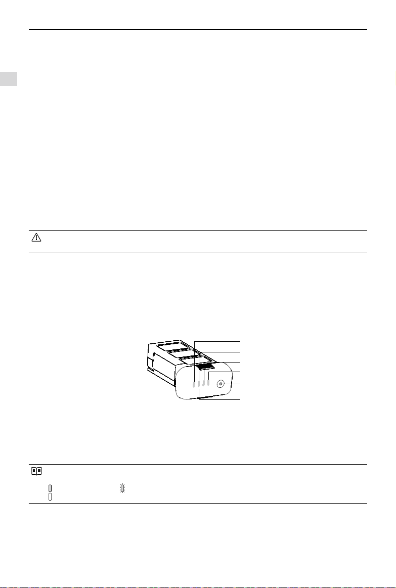
2.1 DJI Smart Flight Battery 7
2.2 Usages 9
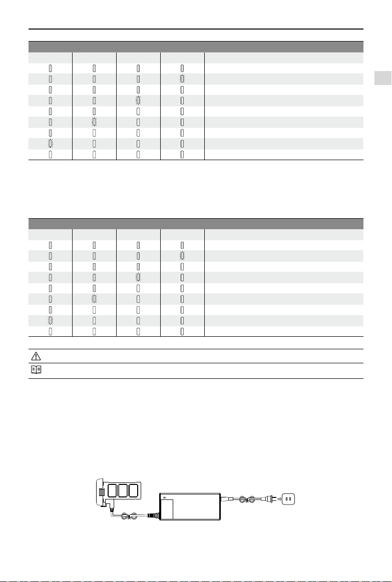
2.3 Charging the Flight Battery 9
2.4 Battery Installation 10
2.5 Correct Battery Usage Notes 10
3 Preparing the Phantom 2 Vision+ 11
3.1 Introduction 11
3.2 Built-in Flight Control System 11
FC Assistant Port 11
3.3 LED Flight Indicator Descriptions 12
3.4 3-axial Stabilized Gimbal 12
Anti-drop Kit 13
Micro-SD Slot 13
Gimbal Error Warnings 13
3.5 Camera 14
Lens cap removal 14
Camera Function Buttons 14
Camera Data Port 14
Camera LED Indicator 15
4 Attaching the Propellers 15
4.1 Introduction 15
4.2 Assembly 15
4.3 Removing the Propellers 16
4.4 Notes 16
5 Preparing the Remote Control 16
5.1 The Remote Control 17
5.2 Power on the Remote Control 17
5.3 Remote Control Power LED Status
Information 17
Contents
5.4 Antenna Orientation 17
5.5 Remote Control Operation 18
5.6
Linking the Remote Control and Receiver
19
Linking Procedures 19
Link Indicator 19
5.7 Compliance Version Conguration 19
6 Preparing the Range Extender 20
6.1 Introduction 20
SYSTEM Indicator 20
POWER Indicator 20
Binding Reset Button 20
6.2 Using Range Extender 20
Charging the Range Extender 20
Powering on the Range Extender 21
Checking the Battery Level 21
6.3 Rename Range Extender SSID 21
6.4 Binding the Phantom 2 Vision+ and
Range Extender 21
7 Downloading and Installing the
DJI VISION App 22
7.1 Download and Install 22
7.2 Register and Login 23
[1] Register 23
[2] Login 23
[3] Usage tips 23
8 Connecting the Camera 24
8.1 Connecting Procedures 24
Wi-Fi Computer Connection Status
Description 24
Flight
Flight Environment Requirements 25
Preight Checklist 25
1 Calibrating the Compass 25
1.1Calibration Procedures 25
1.2 When to Recalibrate 26
2 Starting/Stopping the Motors 26
2.1 Starting Motors 26
2.2 Stopping Motors 26
3 Flight Test 26
3.1Take off/Landing Procedures 26
3.2 Video Suggestions and Tips 27
4 Failsafe Function 27

4
©2014 DJI. All Rights Reserved.
4.1 When Will Failsafe Activate? 27
4.2 Failsafe Procedure 27
Failsafe on the DJI VISION App 28
4.3 Regaining Control During Failsafe
Procedures 28
5
Low Battery Level Warning Function
28
Low Battery Level Warning on the DJI
VISION App 29
6 Flight Limits 30
6.1 Max Height & Radius Limits 30
6.2 Flight Restriction of Restricted Areas 30
6.3 Conditions of Flight Limits 32
6.4 Disclaimer 32
DJI VISION App Usage
1 DJI VISION App Main Menu 32
2 Camera Page 33
[1] Return 33
[2] Camera Pitch Control 33
Normal Mode 33
Accelerometer Sensor Mode 33
[3] Flight Attitude and Radar Function 34
[4] Flight Parameters 34
[5] Wi-Fi Signal Intensity 34
[6] Flight Battery Level 34
[7] Aircraft GPS Status 34
[8] Micro-SD Card Status 34
[9] Range Extender Battery Level 34
[10] Remaining Shots 34
[11] Shutter Button 35
[12] Video Recording Button 35
[13] Camera Settings 35
[14] Hide or Show Flight Parameters 35
3 Camera Settings 35
[1] Capture Mode 35
[2] Photo Size 36
[3] Video Resolution 36
[4] Photo Format 36
[5] Selectable ISO 36
[6] White Balance 36
[7] Exposure Metering 36
[8] Exposure Compensation 37
[9] Sharpness 37
[10] Anti-icker 37
[11] Restore Defaults 37
[12] Format Micro-SD Card 37
4 Album Page 37
4.1 SD Card Album 37
4.2 Mobile Device Photo Album 38
5 News Page 39
6 Settings Page 39
[1] Toolbar Auto Hide 40
[2] When Connection Lost 40
[3] Camera Settings 40
[4] Preview Quality 40
[5] Parameter Unit 41
[6] Ground Station 41
[7] FPV Mode 41
[8] Compass Calibration 41
[9] Low Battery Auto Go Home 41
[10] Rotation Lock 41
[11] Battery Low Warning 41
[12] Tutorial 41
[13] Clear News Cache 41
[14] Binding 41
[15] Rename SSID of Range Extender 41
[16] Find My PHANTOM 2 VISION 41
[17] Account 41
[18] Rate 41
[19] About 41
7 Ground Station 42
7.1 Ground Station GUI 42
7.2 Using Ground Station 43
PC / MAC Assistant
1 Installing Driver and Phantom 2 Vision+
Assistant 45
1.1 Installing and Running on Windows45
1.2 Installing and Running on Mac OS X 45
2 Using Assistant 46
2.1
Using the Phantom 2 Vision+ Assistant
46
2.2
Firmware Upgrade of the Phantom 2 Vision+
46
2.3 Using the Phantom RC Assistant 47
Appendix
1 Rear LED Flight Indicator Status 48
2 Specications 48
3 Troubleshooting (FAQ) 49

©2014 DJI. All Rights Reserved.
5
Overview
The Phantom 2 Vision+ is the next evolution of the Phantom 2 Vision. It features the same App enabled First Person View
(FPV), high performance camera, remote camera control and in-ight content sharing, but adds to it a high performance
3- axial camera stabilization system. It is ideal for aerial creativity whether photo or video. In addition, it provides ground
station function which allows users to plan the ight mission and enables aircraft to ight automatically.
FPV: First Person View, see the world from the perspective of the craft and feel a true ying experience.
1 In the Box
Check that all of the following items have been included in your package before use. If anything is missing, please
contact your local dealer.
NO. Name Picture Qty. Remarks
1Aircraft 1Integrated gimbal and camera
2Propeller Pairs 44 with black nut, 4 with grey
3Micro-SD Card 1Inserted in aircraft Micro-SD slot
4Lens Cap 1 Fixed to camera lens
5Gimbal Clamp 1Attached to the gimbal
6Prop Wrench 1In maintenance packet
7Remote Control 1Includes attached Phone Holder and
Range Extender
8AA Batteries 4For Remote Control
9DJI Smart Flight
Battery 1Inside aircraft
10 Charger 1110-240V Adaptive
11 Power Cables 2GB & CE
12 Plug Adaptors 2SAA & BS
13 Micro-USB Cable 1For range extender charging and
rmware upgrade
In the Box

6
©2014 DJI. All Rights Reserved.
Overview
14 Manuals 4
Including: Disclaimer, Phantom Pilot
Training Guide, Phantom 2 Vision+ Quick
Start Guide, User Manual
15 Stickers 2Colors: Pink, Blue
16 Vibration Absorber 4In maintenance packet
17 Anti-drop Kit 2In maintenance packet
18 Spare Screws 11 In maintenance packet M3X5(6pcs);
M3X8(5pcs)
19 Landing Pad 4In maintenance packet
2 Introduction
The Phantom 2 Vision+ package includes: Phantom, Camera, Gimbal, Propulsion System, Flight Control System,
Remote Control and Wi-Fi Communication System. 5.8 GHz Remote Control Receiver, Flight Control System and 2.4
GHz Wi-Fi Module are inside the Phantom.
Remote Control Outside Working Modes Inside
5.8GHz
2 sticks, 7 channels
3-axial Stabilized Gimbal
Camera
Motors and Props
Phantom-Ready to Fly and Ready
to Fly(non-GPS)
NAZA-M-GPS, ATTI, Manual and
Failsafe
Flight Control System
2.4GHz Wi-Fi Module
5.8GHz Receiver
Electronic Speed
Controls(ESCs)
Mobile Device,
with DJI VISION App
Mobile Device Holder
Range Extender
Remote Control
Aircraft
Motor
Gimbal
Propeller
Camera
Figure 1

Assembly and Use
©2014 DJI. All Rights Reserved.
7
Choose between Phantom and Naza-M working modes using Phantom 2 Vision+ Assistant. If using Naza-M
mode, please refer to the NAZA-M V2 Quick Start Manual for related instructions.
Phantom: Flight settings will be selected automatically depending on whether 6 or more satellites have been
found. This mode allows users to congure the Remote Control and gain values, and use Failsafe and battery
level warnings.
Naza-M: Flight settings will be identical to the Naza-M V2. Users can choose between GPS, Attitude, or Manual
mode. They can also access advanced settings including Intelligent Orientation Control (IOC). Rear LED Flight
Indicators will display the ight status according to the Naza-M indicator.
Ready to Fly: When 6 or more GPS satellites have been found, the Flight Control System will lock its home point
and Rear LED Flight Indicators will blink a slow green ( ). This mode is ideal for beginners.
Ready to Fly (non-GPS): When less than 6 GPS satellites have been found, the Flight Control System will
stabilize itself less than in full Ready to Fly mode and will require more skilled ying. Rear LED Flight Indicators
will blink a slow yellow ( ).
Assembly and Use
Follow the below instructions to prepare for ight.
1 Removing Gimbal Clamp
Pull gimbal clamp in the direction indicated to remove.
Figure 2
2 Preparing the Battery
Ensure all related devices are fully charged before ying the Phantom 2 Vision+.
Device Power supply
Remote Control 4 AA batteries.
Range Extender Charge fully through Micro-USB slot. See Charging the Range Extender (Page
20) for details.
Aircraft (including gimbal and
camera) DJI Smart Flight Battery.
Mobile Device Fully charge before using the DJI VISION App.
2.1 DJI Smart Flight Battery
This battery has been specially designed for the Phantom 2 series. It has a battery capacity of 5200mAh, voltage of
11.1V and charge-discharge management functionality. It can only be charged with a DJI charger or Phantom 2 Car
Charger.
To avoid damage to the gimbal, remove Gimbal Clamp
before powering up the Phantom.
Attach the Gimbal Clamp during transportation or long
term storage to avoid damage.
Smart Flight Battery DJI Charger
Removing Gimbal Clamp / Preparing the Battery
Figure 3 Figure 4

Assembly and Use
8
©2014 DJI. All Rights Reserved.
DJI Smart Flight Battery Functions
(1) Balance Charging Automatically balances the voltage of each battery cell during charging.
(2) Capacity Display Displays current battery levels.
(3) Communication Communicates with Flight Controller about battery voltage, capacity, current and
other relevant information.
(4) Overcharge Protection Charging stops automatically when battery voltage reaches 12.8V to prevent
overcharge damage.
(5) Over Discharge Protection Discharging stops automatically when battery voltage reaches 8.4V to prevent
over discharge damage.
(6) Short Circuit Protection Automatically cuts power supply when a short circuit is detected.
(7) Sleep Protection Sleep mode is entered after 10 minutes of inactivity to save power.
(8) Charging Temperature Detection The battery will charge only when the temperature is between 0℃ (32°F) and
40℃ (104°F).
Battery Specications
Type LiPo
Capacity 11.1V, 5200mAh
Charging Environment Temperature 0°C~40°C
Discharging Environment Temperature - 20°C~50°C
Charging/Discharging Environment Relative Humidity <80%
Please read the user manual, disclaimer, and battery warnings before use. Users take full responsibility for all
operations and usage.
2.2 Usages
Powering on/off
Powering on: Press Circular Power Button once, then press again and hold for 2 seconds to power on. Power Light will
go red and Battery Level Indicators will show the current battery level.
Powering off: Press Circular Power Button once, then press again and hold for 2 seconds to turn off. Battery Level
Indicators will all go out.
Checking the battery level
When the battery is powered off, press the Circular Power Button once. Battery Level Indicators will light up to show
battery level. See below for details.
Battery Level Indicators will show the current battery level during charging and discharging. The indicators are
dened below.
LED is on LED blinks
LED is off
Figure 5
LED2
LED1
Battery Level Indicators
LED3
LED4
Circular Power Button
(Built-in Power Light)
Preparing the Battery

Assembly and Use
©2014 DJI. All Rights Reserved.
9
Discharging process
LED1 LED2 LED3 LED4 Current battery level
87.5%~100%
75%~87.5%
62.5%~75%
50%~62.5%
37.5%~50%
25%~37.5%
12.5%~25%
0%~12.5%
<0%
Battery life
When the battery is powered off, press and hold the Circular Power Button for 5 seconds to check battery life. Battery
Level Indicators will show light up and the Battery Power Indicators will blink for 10 seconds. All lights will then turn off.
For details, please see below.
Battery life
LED1 LED2 LED3 LED4 Current battery life
90%~100%
80%~90%
70%~80%
60%~70%
50%~60%
40%~50%
30%~40%
20%~30%
Less than 20%
When batter life reaches 0, it is no longer operational.
More battery information is available in the battery tab of the Phantom 2 Vision+ Assistant.
2.3 Charging the Flight Battery
(1) Connect charger to wall socket (100-240V, 50/60Hz, using the Plug Adaptors if necessary).
(2) Connect battery to charger. If the current capacity of the battery is over 75%, you should turn it on before beginning
to charge.
(3) Battery Level Indicators will display current capacity level as the battery charges.
(4) Battery is fully charged when Battery Level indicator lights are off. Disconnect the charger and battery when charging
is complete.
Preparing the Battery
Figure 6

Assembly and Use
10
©2014 DJI. All Rights Reserved.
Charging process
LED1 LED2 LED3 LED4 Current battery level
0%~25%
25%~50%
50%~75%
75%~100%
Fully charged
The Smart Flight Battery can be charged using an optional Phantom 2 Car Charger. This can charge the battery
in-car or through 3S-6S Li-Po batteries. Contact your authorized dealer or DJI customer service for details.
Battery should only be charged with the charger provided by DJI. DJI does not take any responsibility for
damage caused by third party chargers.
If current battery level is over 75%, the battery should be turned on before charging.
2.4 Battery Installation
Push battery into battery compartment according to the below diagram. When you hear a click, the battery has been
properly installed.
2.5 Correct Battery Usage Notes
(1) When the battery is turned on, do not connect it to or disconnect it from the Phantom.
(2) Charge and discharge the battery completely once every 20 charge/discharge cycles. Discharge the battery until
there is less than 8% power or until it can no longer be turned on, then recharge it to maximum capacity. This power
cycling procedure will optimize the battery.
(3) For long term storage, place the battery with only a 40~50% charge in a strong battery box. Discharge and charge
the battery once every 3 months to keep it in good condition. Charge amount should be varied in these maintenance
charges - (40%~50%)—0%—100%—(40%~50%).
(4) Purchase a new battery after your current battery has been discharged over 300 times. Completely discharge a
battery prior to disposal. Please dispose of batteries properly.
(5) Purchase a new battery if your current battery swells up or is damaged in any way.
(6) Never recharge or y with a battery that is swollen or damaged in any way.
(7) Never charge batteries unattended. Always charge batteries on a non-ammable surface such as concrete and
never near any ammable materials.
(8) Safety is extremely important. For more information, please see the Disclaimer.
Discharging methods:
Slow: Place battery in Phantom and turn on. Leave on until there is less than 8% of power left or until the battery
can no longer be turned on. See DJI VISION App for battery levels. Motors do not need to be turned on,
reducing wear.
Fast: Fly the Phantom outdoors until there is less than 8% of power left or until the battery can no longer be
turned on.
Figure 7
An incorrectly installed battery may cause
Bad contact,
Unavailable battery information,
Unsafe ight,
Inability to take off.

Assembly and Use
©2014 DJI. All Rights Reserved.
11
3 Preparing the Phantom 2 Vision+
The Phantom 2 Vision+ is a quadrotor with a built-in Flight Control System with integrated gimbal and camera. It features
an FC Assistant Port, Camera Data Port and a specialized battery compartment for its ight battery. All these features
make the Phantom 2 Vision+ easy to assemble and congure.
3.1 Introduction
3.2 Built-in Flight Control System
The Phantom 2 Vision+ is equipped with a DJI Naza-M V2 Flight Control System. This provides incredible ease of use
and stability. Pilots can control the Phantom’s movements in many directions, including pitch (forwards and backwards),
roll (left and right), elevator (up and down) and yaw (turn left or right). The ight control system also can provide IOC,
Failsafe and battery level warnings.
Modules Functions
Flight Controller Acts as the brains of the complete flight control system, responsible for connecting and
controlling all the modules together.
IMU Has a built-in inertial sensor and a barometric altimeter that measures both attitude and
altitude.
GPS & Compass The compass reads geomagnetic information and assists the GPS (Global Position System)
to accurately calculate the position and height of the aircraft.
LED Flight Indicators Indicates the status of ight control system.
FC Assistant Port
The ight control system communicates with the PC Assistant through a Micro-USB cable between the Phantom FC
Assistant Port and the PC. Users can use Assistant to congure the aircraft and upgrade the Phantom rmware. Please
refer to Using the Phantom 2 Vision+ Assistant (Page 46) for details.
[1]
[2]
[3]
[4]
[5]
[6]
[7]
[8]
[9]
[10]
[11]
[12
]
[13]
[14]
[15]
[16]
[17]
[18]
Propeller
Motor
Front Sticker
Front LED
FC Assistant Port (Micro-USB slot)
Vibration Absorber
Camera LED Indicator
Camera Function Button
Anti-drop Kit
3-axial Stabilized Gimbal
Camera Lens
Rear LED Flight Indicator
DJI Smart Flight Battery
Receiver Antenna
Landing Gear
Camera Data Port (Micro-USB slot)
Compass
Micro-SD Slot
[12]
[13]
[14]
[15]
[1]
[2][3]
[4]
[5]
[6][7]
[8]
Figure 10
Figure 8
Figure 9
[16]
[17]
[18]
[11]
[10]
[9]
Preparing the Phantom 2 Vision+

Assembly and Use
12
©2014 DJI. All Rights Reserved.
Figure 11 Figure 12
Rear LED Flight Indicators Normal Notes
Red, Green, Yellow
ashing in turn Power On Self-Test
Yellow,Green ashing in turn Warming Up Aircraft cannot take off.
Slow Green ashing Ready to Fly More than 6 GPS satellites are found.
Slow Yellow ashing Ready to Fly (non-GPS) Less than 6 GPS satellites are found.
Rear LED Flight Indicators Abnormal Notes
Quick Yellow ashing Remote Control Signal Lost Refer to Failsafe Function (Page27) for
details.
Slow Red ashing Low Battery Level Warning DJI VISION App will also show warning
message.
Quick Red ashing Critical Low Battery Level
Warning
DJI VISION App will show warning
message.
Three Red ashing off and on Not Stationary or Sensor Bias is
too big
Keep aircraft stationary or perform IMU
calibration.
—
Solid red Error Cannot y.
Red, Yellow ashing in turn Compass Needs Calibration Refer to Calibrating the Compass
(Page25) to get details.
If a solid red LED indicator appears, connect to the Phantom 2 Vision+ Assistant for details and resolution.
This may be caused by:
IMU calibration required: Recalibrate IMU using Assistant.
IMU is abnormal: Repair required.
Compass is abnormal: Repair required.
Remote Control mid-point is set abnormally: Refer to How to solve large margin(s) mid-point error? (Page 49)
3.4 3-axial Stabilized Gimbal
The 3-axial stabilized gimbal of the Phantom 2 Vision+
will power on and self-check each time the ight battery
is installed and powered on. Its pitch can be controlled
using the DJI VISION App. This gimbal has two working
modes, Non-FPV mode and FPV mode, with the Non-FPV
mode set as default. This can be congured in Phantom 2
Vision+ Assistant or the DJI VISION App.
3.3 LED Flight Indicator Descriptions
LED ight indicators are found at the front and the rear of the Phantom. Front LEDs are for indicating where the nose of
the aircraft is. They light up solid red after motors have started spinning. Rear LED Flight Indicators light up to show the
aircraft’s current ight status once the ight battery is powered on. For details, please see the below table.
Front LEDs Rear LED
Flight Indicators
Preparing the Phantom 2 Vision+
Figure 13

Assembly and Use
©2014 DJI. All Rights Reserved.
13
Figure 14
Gimbal specications
Control accuracy ±0.03°
Controllable range Pitch : -90°~0°
Maximum angular velocity Pitch : 90°/s
Non-FPV Mode: the gimbal will stabilize across 3-axial for smooth aerial creativity.
FPV Mode (First Person View Mode): Gimbal will lock to the movements of the Phantom for a FPV experience.
Anti-drop Kit
The Anti-drop Kit helps keep the gimbal and camera
connected to the aircraft. Two have been mounted on
delivery. If new ones are required, take the gimbal and
press part [1]through the center hole of the Vibration
Absorber the center hole of part [2]. Lock them together
as shown in [3]. Mounting the Anti-drop Kit diagonally is
recommended.
Once part [1] and part [2] are connected, the Anti-drop Kit cannot be disconnected and reused.
Micro-SD Slot
With ight battery powered off, make sure the Micro-SD
card is inserted correctly into the Micro-SD Slot before
taking any photos or recording any video.
The Phantom 2 Vision+ comes with a 4GB Micro-SD card
and can support cards up to 32GB. The DJI VISION App
may not be able to read some Micro-SD cards. Using
the DJI VISION App to reformat new Micro-SD cards is
recommended.
Refer to Format Micro-SD Card (Page 37) for details.
Do not insert or remove Micro-SD card when ight battery is powered on.
Gimbal Error Warnings
Before the aircraft takes off, if a gimbal motor error is detected or the gimbal clamp is not removed, there will be a
warning prompt on the camera page of the DJI VISION App. This will disappear after the problem is resolved.
Figure 15
Figure 16 Figure 17
[2]
[1][3]
Preparing the Phantom 2 Vision+

Assembly and Use
14
©2014 DJI. All Rights Reserved.
Figure 18
Figure 19
Photos and videos can only be copied when the ight battery is powered on.
Remove gimbal clamp before powering on ight battery.
Gimbal motor error may occur in these situations: (1) Gimbal is placed on uneven ground. (2) Gimbal has
received an excessive external force, e.g. a collision. Please take off from at, open ground and protect the
gimbal after powering up. Flying in heavy fog or cloud may make the gimbal wet, leading to a temporary
failure. The gimbal will recover when it dries out.
3.5 Camera
The Phantom 2 Vision+ camera powers up when the ight battery has been installed and switched on. Photos and
videos can be shot by pressing either the onboard button or the DJI VISION App. For aerial photography it supports
burst shots, continuous capture and timed capture, and exports to both Adobe DNG Raw and JPEG. For aerial video, it
shoots in full HD at (1080p30/1080i60) and can even shoot 720p60 for internet ready slow motion.
Camera specications
Sensor Size 1/2.3”
Pixels 14 Megapixels
Resolution 4384×3288
HD Recording 1080p30 /1080i60/720p60
Recording FOV 110° / 85°
Lens cap removal
Remove lens cap before use and replace it when
shooting is complete to protect the camera lens.
Camera Function Buttons
Capture: Press (hold less than 2 seconds) to take a single
capture.
Record: Press (hold more than 2 seconds) to begin
recording. Press again to stop.
Camera Data Port
Connect the Camera Data Port to a PC using a Micro-
USB cable to copy les to a PC.

Assembly and Use
©2014 DJI. All Rights Reserved.
15
Camera LED Indicator
Camera LED Indicator lights up after the ight battery is powered on. It provides information on the working status of the
camera.
Camera LED Indicator Wi-Fi status Camera status
Green Solid OFF Power On; Idle
Slow Green Blink (0.2s on, 1.8s off) ON Idle
Green Blink(0.1s on, 0.3s off, 0.1s on, 1.8s off) ON Micro-SD card connected to PC
Fast Green Blink (0.1s on, 0.3s off) ON Synchronizing
Orange Solid OFF Recording
Orange Blink Once (0.2s on, 0.3s off) ON / OFF Taking a single picture.
Orange Blink 3 Times(0.1s on, 0.1s off) ON / OFF Taking 3 or 5 photos per shot
Orange Fast Blink (0.1s on, 0.3s off) ON / OFF Firmware Upgrading
Green, Orange (0.2s green, 1.8s orange) ON Recording
Red Solid ON / OFF Critical error
Slow Red Blink (0.2s on, 1.8s off) ON / OFF CMOS sensor error
Red Blink Once (0.2s on, 0.3s off) ON / OFF Operation failed
Red Blink 3 Times(0.1s on, 0.1s off) ON / OFF Micro-SD card error
Fast Red Blinks (0.1s on, 0.3s off) ON / OFF Upgrade error
Fast Green, Orange and Red Blink
(0.1s on, 0.3s off) ON / OFF Overheated Camera
4 Attaching the Propellers
Always use original 9-inch propellers, classied by the color of each central nut.
4.1 Introduction
Propellers Grey Nut (9443) Black Nut (9443 R)
Diagram
Assembly Location Attach to motor without black dot. Attach to motor with black dot.
Fastening/
Un-fastening
Instructions
Lock: Tighten propeller in this direction.
Unlock: Loosen propeller in this direction.
4.2 Assembly
(1) (Figure 20) Remove warning cards from motors after you have read them.
(2) (Figure 21) Spin grey marked propellers clockwise onto unmarked motors and black marked propellers anti-
clockwise for black marked motors.
Figure 20 Figure 21
Attaching the Propellers

Assembly and Use
16
©2014 DJI. All Rights Reserved.
Propellers self tighten during ight. DO NOT use thread locker.
Always match marked props with the corresponding motor.
Protective gloves are recommended during propeller assembly and removal.
4.3 Removing the Propellers
(Figure 22) Prevent motor rotation using the included wrench or a
hand, then remove propeller according to the un-fastening instructions.
4.4 Notes
(1) Check that propellers and motors are installed correctly and rmly
before every ight.
(2) Ensure that all propellers are in good condition before each ight.
DO NOT use any ageing, chipped, or broken propellers.
(3) To avoid injury, STAND CLEAR of and DO NOT touch propellers or
motors when they are spinning.
(4) ONLY use original DJI propellers for a better and safer ight experience.
For beginner yers, Phantom 2 Prop Guards are recommended. Contact your authorized dealer or DJI customer
service to purchase if necessary.
5 Preparing the Remote Control
The Phantom 2 Vision+ Remote Control is a wireless communication device using the 5.8GHz frequency band. Remote
Control and Phantom are paired before delivery.
The Remote Control is set to Mode 2 by default. This can be adjusted in the PHANTOM RC Assistant. See Using the
PHANTOM RC Assistant (Page 47) for details. You can also adjust the power of your Remote Control according to
national regulations. Please refer to Compliance Version Conguration (Page 19).
Compliance Version: The Phantom 2 Vision+ Remote Control is compliant with CE and FCC (see the FCC ID)
regulations.
Operating Mode: Mode 1 and Mode 2 refer to different channel mappings.
Mode 1: The right stick controls throttle.
Mode 2: The left stick controls throttle.
The Range Extender and Phone Holder are already mounted on the Remote Control. Twist the Mobile Device
Holder to face outwards and x it in position for mobile device installation.
Large smartphones and tablets are not recommended for the Phone Holder as they do not t.
Preparing the Remote Control
Figure 22
Figure 23

Assembly and Use
©2014 DJI. All Rights Reserved.
17
5.1 The Remote Control [1]
[2]
[3]
[4]
[5]
[6]
[7]
[8]
[9]
[10
]
[11
]
Antenna
Carrying Handle
Switch S1
Switch S2 (Reserved)
Right Stick: J1, Roll [left & right],
J2, Pitch [front & back]
Left Stick: J3, Throttle [up & down],
J4, Yaw [rotation]
Neck Strap Attachment
Power Switch
Power LED
RC Assistant Port (Micro-USB slot)
Battery Compartment (On the back)
5.2 Power on the Remote Control
(1) Install four AA batteries into the battery compartment on the back of the Remote Control. Pay
attention to positive and negative.
(2) Set S1 and S2 switches to the upper most position and place all sticks in the mid-point.
(3) Toggle power switch to the right to switch on.
(4) The Remote Control will then beep. If it is set to CE compliance, then there will be one beep
while the FCC compliant version will beep twice. The Power LED will blink green quickly
indicating that the Remote Control and receiver are binding. Once binding is completed, the
Power LED will change to a solid green.
If the low voltage warning alert sounds (refer to Remote Control Power LED Status Information (Page 17) for
details), replace batteries as soon as possible.
For long term storage, be sure to remove the batteries from Remote Control.
Dispose of batteries properly.
5.3 Remote Control Power LED Status Information
Power LED Sound Remote Control State
—
Solid Green None Functioning normally.
Quick Green ashing None Establishing a link between the Remote Control and the receiver.
Slow Red ashing B-B-B…… Low voltage (at 3.9V-4.5V). Replace batteries as soon as possible.
Quick Red ashing BBBB Low voltage (lower than 3.9V). Remote Control will automatically
power off. Replace batteries immediately.
Slow Green ashing B--B--B…… Remote Control has not been operated for 15 minutes. Turn off or
use the Remote Control.
The Remote Control Power LED will blink red and sound an alert when the voltage drops below 3.9V and
automatically power off after 3 seconds. This process will repeat even if you power cycle the Remote Control. If
this low voltage warning occurs during ight, it will cause the Phantom to enter Failsafe mode which cannot be
interrupted (refer to Failsafe Function (Page27) for details). Replacing batteries immediately after the low voltage
warning (3.9V-4.5V) is strongly recommended.
5.4 Antenna Orientation
Keep the antennas pointing skyward, perpendicular to the ground for maximum remote control range during ight.
[1]
[2]
[3]
[4]
[5]
[6]
[7]
[8]
[9]
[10]
[11]
J3
J4
J2
J1
For maximum range and reliability, Remote Control antenna should point skywards with
no obstructions between it and the Phantom. Obstacles may cause Return to Home to
trigger. Phone Holder and Range Extender should not block the antenna.
Preparing the Remote Control
Figure 24
Figure 25

Assembly and Use
18
©2014 DJI. All Rights Reserved.
5.5 Remote Control Operation
The Remote Control is set to Mode 2 by default.
Stick Neutral/ mid point: Control sticks of the Remote Control are placed at the central position.
Move the Stick: The control stick is pushed away from the central position.
Remote Control
(Mode 2)
Aircraft
( indicates nose direction) Operation details
Vertical movements on the left stick control elevation.
Push the stick up to ascend and down to descend.
When both sticks are centered the Phantom will hover in
place.
Push the throttle stick upward beyond the centered
(neutral) position to take off. Push the throttle gently to
prevent sudden and unexpected elevation.
Horizontal movements on the left stick control the rudder.
Push left to rotate counter clock-wise and right for
clockwise. If the stick is centered, the Phantom will fly
straight.
The more the stick is moved, the faster the Phantom will
rotate.
Vertical movements on the right stick control forward and
backward pitch.
Push up to fly forward and down to fly backward. The
Phantom will hover in place if the stick is centered.
Push the stick further for a larger pitch angle (maximum
35˚) and faster ight.
Horizontal movements on the right stick control left and
right pitch.
Push left to y left and right to y right. The Phantom will
hover in place if the stick is centered.
Push the stick further for a larger pitch angle (maximum
35˚) and faster ight.
Position 1 Position 2 Position 3
The S1 switch is used for compass calibration.
Toggle the S1 from position 1 to position 3 and back
approximately 5 times to enter into compass calibration
mode.
In Naza-M mode, the S1 switch is used to switch
between control modes and enter compass calibration.
Position 1 Position 2 Position 3
S2 is used to record a Home point manually. After a
Home point has been recorded automatically, flipping
S2 from position 1 to position 3 and back 5 times (or
more) rapidly will move the Home point to the Phantom’s
current location.
In Naza-M working mode, S2 is be used for IOC.
In ‘Ready to Fly’ mode, the Phantom will hover when all sticks are released.
In ‘Ready to Fly (non-GPS)’ the Phantom will lock its altitude but will not have horizontal positioning.
Preparing the Remote Control

Assembly and Use
©2014 DJI. All Rights Reserved.
19
Linking Procedures
(1) Power off the Remote Control, power on the aircraft.
You will see the link indicator blinking red.
(2) Press the link button with a thin object and hold
until the link indicator blinks yellow. Release the link
button.
(3) Power on the Remote Control. Link indicator will
switch off, showing that a link has been successfully
established.
Figure 27
Link Indicator
Link Indicator Description Next Operation
Red ashing No signal received. Switch on the Remote Control or perform a link procedure.
Yellow ashing Ready to link. Switch on the Remote Control.
5.7 Compliance Version Conguration
As power levels vary between regulators, the Phantom Remote Control’s power output can be adjusted by twisting the
CE/FCC Control Knob (Figure 27) on the back of the Remote Control using a athead screwdriver. For CE compliance,
set the Remote Control to CE with a full counterclockwise turn. For FCC compliance, set the Remote Control to FCC with
a full clockwise turn. Be sure to follow relevant local regulations.
Compliance can be congured using the PHANTOM RC Assistant. Select CE compliance version in Assistant to set it, or
do the same with FCC compliance version.
5.6 Linking the Remote Control and Receiver
A 5.8G receiver is built in to the Phantom 2 Vision+. Its link button and indicator are located on the underside of the
phantom, as shown in Figure 26.
The Remote Control and the receiver are paired before delivery. Only use this button if you have replaced your Remote
Control or receiver.
Turn the CE/FCC Control Knob gently to avoid
damage.
CE compliant devices have an effective remote
control range of 400 meters in open spaces due
to power limitations.
FCC compliant devices have an effective range of
800 meters in open spaces.
Watch your flight distance as the Phantom 2
Vision+ will enter Failsafe mode (auto-landing or
go home and land) if it ies beyond the relevant
range limits.
Always follow local laws and regulations.
It is recommended to use a Φ2.4mm flathead
screwdriver for adjustments.
There is another potentiometer for reserved use.
CE FCC
Preparing the Remote Control
Figure 26
Link Button & Link
Indicator

Assembly and Use
20
©2014 DJI. All Rights Reserved.
6 Preparing the Range Extender
The Phantom 2 Vision+ Range Extender is a wireless communication device that operates within the 2.4 GHz frequency
band. It is used to extending the effective range of communication between a Smartphone and the Phantom 2 Vision+.
In an open, unobstructed area, the transmission distance can reach up to 700 meters. This can be reduced by trees,
buildings and other sources of the same frequency. Before every ight, it is suggested that you ensure the Range
Extender is functioning properly; otherwise communication issues between the mobile device and the Phantom 2
Vision+ may occur.
Each Range Extender has a unique MAC address and network name (SSID), details of which are printed on the label as
‘Phantom_XXXXXX’. The ‘XXXXXX’ represents the last 6 letters or numbers of the MAC address for the Range Extender.
This can be renamed in the DJI VISION App.
6.1 Introduction
[1]
[2]
[3]
[4]
[5]
[6]
[7]
SYSTEM Indicator
POWER Indicator
Locking Screw
Binding Reset Button
Power Switch
Charging Port(Micro-USB slot)
Mounting Bracket
SYSTEM Indicator
Shows Wi-Fi status of the Range Extender.
SYSTEM Indicator Description
Green ashing The Wi-Fi network is functioning normally.
Off The Wi-Fi network is functioning abnormally.
POWER Indicator
Shows power levels of the Range Extender.
POWER Indicator Description
Solid green Fully charged.
Solid red Low voltage alert, re-charge required.
Solid Yellow Charging.
If the power indicator is a solid red light, the Ranger Extender may stop working at any moment. Land and
recharge as soon as possible.
Binding Reset Button
When the Binding Reset Button is pressed, it will reset and restart the Range Extender. You will need to bind it with the
Phantom 2 Vision+ again to recreate its Wi-Fi network. Failure to do so will cause the DJI VISION App to fail to connect
with the camera.
6.2 Using Range Extender
Charging the Range Extender
Charge the Range Extender by connecting the charging port to a power supply device such as a PC or a USB charger
using a Micro-USB cable. Make sure to charge the Range Extender completely before using it for the rst time. This
takes 3~4 hours depending on USB power output.
Make sure the Range Extender has enough power before each use.
Figure 28 Figure 29
[1]
[2]
[3]
[5]
[4]
[6]
[7]
Preparing the Range Extender
Other manuals for Phantom 2 Vision +
17
Table of contents
Other dji Quadcopter manuals

dji
dji Flamewheel F450 User manual

dji
dji Phantom 2 Vision + User manual

dji
dji MAVIC MINI User manual

dji
dji Inspire 1 User manual

dji
dji Phantom 2 Vision + User manual

dji
dji mavic User manual

dji
dji Phantom 3 Advanced User manual

dji
dji INSPIRE 2 User manual

dji
dji Phantom 4 RTK Instruction Manual

dji
dji Matrice 100 Installation and operating manual

dji
dji Matrice 600 Pro User manual

dji
dji S?1000 User manual

dji
dji MAVIC PRO User manual

dji
dji MATRICE 200 User manual

dji
dji INSPIRE 2 Operating instructions

dji
dji Phantom 3 Advanced User manual

dji
dji AGRAS MG-1S User manual

dji
dji GeoSnap PPK Quick setup guide

dji
dji Tello User manual

dji
dji Matrice 100 User manual