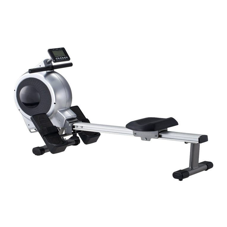
DKN SMART POWER MACHINE User manual

1
SMART POWER MACHINE
OWNER’S MANUAL
WEBSITE
OWNER’S MANUAL

2

3
Content
--------------------------
-------------------------
--------------------------
--------------------------------
------
----------------------------
-----
------------
-------

4
Chapter 1.Safety Instructions
Please read the safety information carefully before use the machine.
1. Safety warning
Electrical current from power, telephone, and communication cables is
dangerous . To avoid the risk of electric shock:
plug or unplug cables , nor install, maintain , or reconfigure this product
during a thunderstorm .
Connect the power cord correctly and use a well - grounded power outlet.
Whenever possible, use only one hand to connect or disconnect device
cables .
Never turn on any equipment when there are signs of fire, flooding, or house
collapse.
Unless otherwise instructed during installation and configuration, disconnect
equipment such as power cords, telecommunication systems, networks, and
modems that are connected before opening the equipment cover .
installing, moving , or removing the back cover of this product , plug and
unplug device cables as described in the following table :
When connected , do the following:
1. Turn off all devices
2. Connect the power cable to the
device
3. Connect the signal cable to the
corresponding port
4. Connect the power cable to the
socket
5. Turn on the device
When disconnected , do the following:
1. Turn off all devices
2. Unplug the power cord from the
power outlet
3. Unplug the signal cable from each
connector
4. Unplug the power cord from the
device

5
2. Matters needing attention
1. When replacing the system battery, please use the same type of battery for
replacement.
2. Some batteries contain lithium, which may explode if used, handled or
handled improperly . To prevent accidents, do not:
Throwing or immersing the battery in water
Heat the battery to over 100°C (212°F)
Repair or disassemble the battery without authorization
3. The power control button on the device and the switch on the power supply
may not completely cut off the current supplied to the device ; at the same time, the
device may also have multiple power cords . To completely power down the device,
make sure all power cords are disconnected.
4. Never remove any component housing that has a hazard label attached .

6
WARNING! Consult your physician before starting with any exercise program. He can advise on
the kind of training and which impact is suitable.
WARNING! This machine is not suitable for therapeutic or medical purpose.
WARNING! Over exercising may result in serious injury or death. If you experience dizziness,
nausea, chest pain, or any other abnormal symptoms STOP EXERCISING IMMEDIATELY AND
CONSULT A PHYSICIAN WITHOUT DELAY.
WARNING! Inappropriate use of this machine such as while under the influence of drugs or alco-
hol, not in line with instructions or excessive usage, may result serious injury or death.
WARNING! Incorrect/excessive training may cause health injuries.
►The owner’s manual is only for customers’ reference.
►The supplier cannot guarantee for mistakes occurring due to translation or change in
technical specification of the product.
►DKN-Technology ASSUMES NO RESPONSIBILITY FOR PERSONAL INJURY OR
PROPERTY DAMAGE SUSTAINED BY OR THROUGH THE USE OF THIS PRODUCT

7
Chapter 2.Product Appearance
Front view
back view

8
side view
Disassembly back view
AC outlet and AC switch

9
Chapter 3.Disassembly guide
I. Explosion diagram of the whole machine(Send as attachment)

10
NO. NAME QTY NO. NAME QTY NO. NAME QTY
1 Screen Bracket 1 21 Cylinder 2 41 Left Shield Upper
Cover 1
2Short Edge
Foam 2 22 Slow Drop
Wheel Assembly 2 42 Left Shaft Sleeve
Decorative Cover 1
3Long Edge
Foam 223 Right Rack
Assembly 1 43 Motor 2
4 4.3 Inch Screen 1 24 Roller Shaft 4 44 Axle Sleeve Soft
Parts 2
5 Screen Mount 4 25 Roller 6 45 Motor Mount 2
6 Knob 1 26 Suction Shaft 1 46 Wire Rope Buckle 2
7Start-Stop
Button 1 27 Iron Shaft Spring 1 47 Wire Rope Guard
Cover 2
8 Knob Foam 1 28 Torsion Spring 1 48 Travel Switch
Bracket 2
9R11
Motherboard 1 29 Tie Rod Piece 1 49 Limit Switch 2
10
Right Bushing
Decorative
Cover
1 30 Copper Sets 8 50 Reel Flange 2
11 Right Shield
Cover 1 31 Folding Board 2 51 Reel Spline Shaft 2
12 Long Pole
Bracket 2 32 Over-the-line
Plastic Parts 2 52 Kevlar Wire Rope 2
13 Pedal 2 33 Folding Handle 1 53 Wire Rope Guard
Lower Cover 2
14 Trumpet 2 34 Folding Wire
Rope 1 54 Wire Rope
Stopper 2
15 Speaker
Bracket 4 35 Folding Switch
Handle 1 55 Reel 2
16
Motor And
Motor Control
Fixing Bracket
2 36 Left Shield
Bottom Cover 1 56 Adjust Button 1
17 Motor Control
Fixing Bracket 2 37 Foot Pad 8 57 PFC Wide Voltage
Module 1
18 Motor Control
Components 4 38 Magnet 1 58 Power Filter 2
19 Swivel Wheels 4 39 Magnet Bushing 1
20 Right Shield
Bottom Cover 1 40 Left Rack
Assembly 1

11
II. Screw tightening torque reference table
Torque Requirements (Except Thumb Screws and Nuts)
Thread Specification
(mm)
Tightening torque
N.M (kgf.cm)
M3x4~M3x8 0.5-0.7 5-7
M4x8~M4x12 0.7-1.0 7-10
M5 1.2-1.5 12-15
Tools Used
Num
berin
g
Screw
Pictures
Name Specification
A Cross recessed B head screw BM1.7×5mm black nickel plated
BCross recessed countersunk
head screws KM4×8mm black nickel plated
CCross recessed B head screw BM4×16mm-Black Nickel Plated

12
D Cross recessed B head screw ST4×8mm-nickel plated
ECross recessed K head screw KM5×24mm-Black Nickel Plated
FCross recessed K head screw KM6×12mm-Silver Nickel
Plated-Fall Resistant
GHexagon head screw M8×12mm-Black Nickel
Plated-Fall Resistant
HPhillips T-head screw TM4 ×10mm-Black Nickel
Plated
ICross recessed P head screw PM4x8mm-With Outer Spline
Meson-Nickel Plating
JCross recessed P head screw PM5×6mm-black oxidizer
KCross recessed B head screw BM5×10mm-Black Nickel Plating
LCross recessed pan head screw
with pad PWM3.0×6mm-Nickel plating

13
M Hex nuts
M
8×8mm-nickel plated
NPhillips B head screw
B
M2×6mm-nickel plated
OPhillips B head screw
B
M2×8mm-nickel plated
PPhillips B head screw
B
M3×6mm-nickel plated
RPhillips B head screw
B
M4×16mm-Nickel Plated-Large
G
asket

14
III.Screw and Foam Location Information Sheet
Serial
number Material Specifications Location A arrive Position B
Unit
dosage
Number
of parts
Total
amount total
1 ST1.4×4mm self-tapping screw Wireless Switch
Board -> Wireless Switch
Button 4 1 4 4
2 ST1.7×4mm self-tapping screw Screen Mount -> Screen Bracket 4 1 4 4
3 STA2×6mm self-tapping screw Screen Bracket -> Right Shield
Cover 4 1 4 4
4 STA2×8mm self-tapping screw Limit Switch -> Travel Switch
Bracket 1 2 2 2
5 ST3×6mm self-tapping screw
R11 Motherboard -> Right Shield
Cover 4 1 4
16
Bushing
Decorative Cover -> Right Shield
Cover 4 1 4
Bushing
Decorative Cover -> Left Shield Upper
Cover 4 1 4
Wire Rope
Stopper -> Reel 2 2 4
6ST4×8mm self-tapping
screw flat tail
Right Shield
Bottom Case -> Right Shield
Upper Shell 10 1 10
36
Left Shield
Bottom Case -> Left shroud upper
shell 10 1 10
Speaker bracket -> right rack 2 1 2
Speaker bracket -> left rack 2 1 2
Wire Rope Guard -> Wire Rope Guard 6 2 12
7ST4×16mm self-tapping
screw tip tail
Left shield bottom
case -> Left shroud upper
shell 14 1 14
28
Right shield
bottom case -> Right shield upper
shell 14 1 14
8 M3×6mm machine screw trumpet -> Speaker bracket 2 2 4 4
9 M3×10mm machine screw motor mount -> motor 8 2 16 16
10 M4×10mm machine screw
Travel switch
bracket ->
Motor & Motor
Control fixing
bracket
1 2 2
29
Wire Rope Guard -> motor mount 4 1 4
motor mount -> Wire Rope Guard 4 1 4
Right shield
bottom case -> right rack 8 1 8
Left shield bottom
case -> left rack 8 1 8

15
PFC Wide Voltage -> right rack 3 1 3
11 M4×8mm countersunk
head (K head) screw
Over-the-line
plastic parts -> folding board 2 2 4 4
12 M4×16mm machine screw foot pad -> right rack 4 1 4 8
foot pad -> left rack 4 1 4
13 M4*16 machine tooth
combination screw Spline shaft -> Motor shaft 1 2 2 2
14 M5×6mm machine screw Speaker bracket ->
Motor & Motor
Control fixing
bracket
2 2 4 6
15 M5×10mm machine screw
Motor & Motor
Control board
fixing bracket
-> heat sink 4 2 8
22Motor & Motor
Control fixing
bracket
->
Motor Control
board fixing
bracket
4 2 8
Reel Flange -> motor mount 3 2 6
16 M5×16mm machine screw Tie rod piece -> folding wire 1 1 1 1
17 M5×24mm countersunk
head (K head) machine screw long pole bracket ->
Motor & Motor
Control fixing
bracket
2 2 4 4
18 M6×12mm machine screw
board -> right rack 6 1 6
13board -> left rack 6 1 6
right rack -> suction shaft 1 1 1
19 M8×12mm machine screw
Motor & Motor
Control fixing
bracket
-> Motor mount 4 2 8 8
20 M8×30mm machine screw
right rack -> Tie rod piece 1 1 1
3right rack -> cylinder 1 1 1
left rack -> cylinder 1 1 1
21 M5 nylon nut Tie rod piece -> folding wire 1 1 1 1
22 M8 nylon nut
right rack -> Slow drop wheel
assembly 1 1 1
14
Slow drop wheel
assembly -> cylinder 1 2 2
right rack -> Tie rod piece 1 1 1
right rack -> cylinder 1 1 1
left rack -> cylinder 1 1 1
Motor & Motor
Control fixing
bracket
-> right rack 4 1 4
Motor & Motor
Control fixing -> left rack 4 1 4

16
bracket
23 M8 gasket (Φ16×Φ8.5×2mm) Bull's Eye Wheel ->
Motor & Motor
Control fixing
bracket
1 4 4 4
24 M10 flat pad (Φ18×Φ10.5×1.5mm) plug screw -> frame 1 8 8 8
25 PWM3×6mm, with spacer screw,
spacer diameter 9mm trumpet -> Speaker bracket 2 2 4 4
26 PM4×5mm with external tooth
meson, ground screw Ground wire -> frame 1 1 1 1

17
IV. Disassembly of structural parts
1. Take out the Long Rod Bracket, the Screw positions are as follows;
Repair Instructions
Before removing the Long Pole Bracket, it is recommended to lay the machine
flat on the platform, and then use a screwdriver to unscrew the 4 screws shown in the
figure. The picture above shows the position of the screws of the Long Pole Bracket,
and different colors represent different screw types. After unscrewing these screws,
the Long Pole Brackets on both sides can be removed.
Note that the tightening torque used must comply with the reference values for
the specific type of screw. Otherwise the screws may be permanently damaged.

18
2. Take out the Swivel Wheels, the Screw Positions are as follows;
Turn clockwise to tighten
Turn counterclockwise to loosen
Repair Instructions
Directly align the plum blossom slot at the bottom of the swivel wheel with the
Special Dismantling Tool for Swivel Wheel, and turn it counterclockwise to remove
the 4 Swivel Wheels.(The Special Dismantling Tool is inside the bottom)
Note that the tightening torque used must comply with the reference values for
the specific type of screw. Otherwise the screws may be permanently damaged.

19
3. Take out the Bottom Shells of the left and right shields and the Upper
Covers of the left and right shields. The screw positions are as follows;
Repair Instructions
Before removing the Bottom Cover of the left and right shields, it is
recommended to lay the machine flat on a platform with a protective cushion, and
then use a screwdriver to unscrew the screws shown in the figure. The above picture
shows the position of the screws, and different colors represent different screw types.
After unscrewing these screws, the left and right shield bottom shells can be removed;
After removing the left and right shield bottom shells, first remove and straighten
the 485 Communication Cable, Speaker Cable and Upgrade Serial Cable Connected
to the display motherboard from the socket and the machine, and then turn the whole
machine over. First remove the soft rubber part of the shaft sleeve, and then remove
the upper cover of the left and right shields upward;
Note that the tightening torque used must comply with the reference values for
the specific type of screw. Otherwise the screws may be permanently damaged.
When removing the upper cover of the right shield, you need to carefully take out
the 485 Communication Cable, Speaker Cable and Serial Port Cable Connected to the
lower control together with the upper cover.

20
The bottom cover of the right shield cannot be completely removed because the
AC Socket and Power Cord are installed. You only need to lift the bottom cover of
the right shield to 90 degrees to connect the 485 Communication Cable, Speaker
Cable and Serial Port for upgrading to the display motherboard. Remove and
straighten the cord from the socket and machine to replace the right shield bottom
cover and turn the machine over.
4. Take out the pedal, the screw positions are as follows;
Repair Instructions
Use a screwdriver to remove the 12 screws shown in the figure. The picture
above shows the location of the screws that hold the pedals in place. After removing
these screws, the pedals on both sides can be removed.
Note that the tightening torque used must comply with the reference values for
the specific type of screw. Otherwise the screws may be permanently damaged.
Table of contents
Other DKN Fitness Equipment manuals
Popular Fitness Equipment manuals by other brands

Stages cycling
Stages cycling SP3 installation guide

Keys Fitness
Keys Fitness ST-IB owner's manual

Hoist Fitness
Hoist Fitness Prime-8 owner's manual

Mannsberger
Mannsberger 50197 manual

OYMotion Technologies
OYMotion Technologies gForceDual Neuro Rehab user guide

MAYHEM STRENGTH
MAYHEM STRENGTH HAVOC Series Assembly instructions