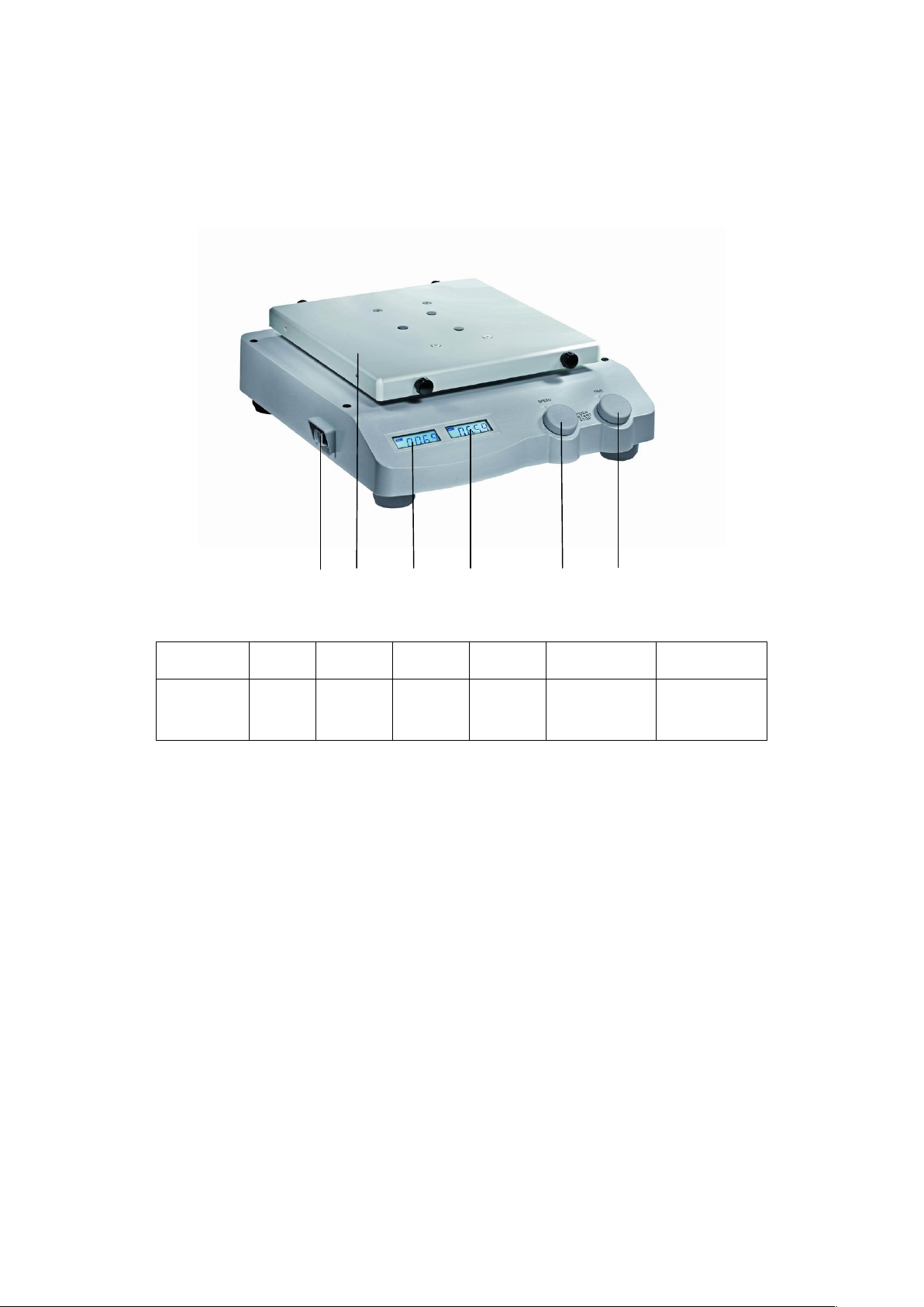
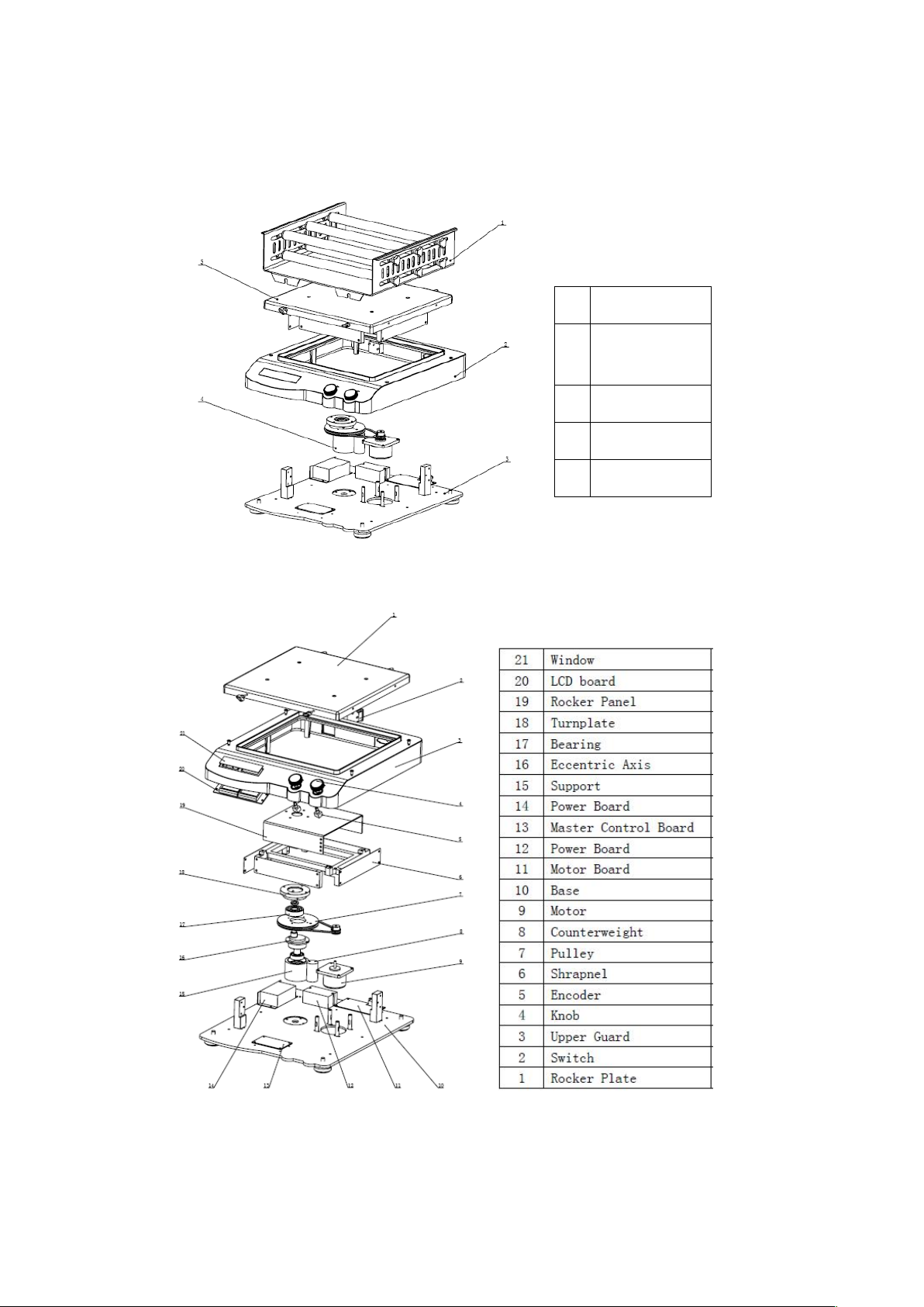
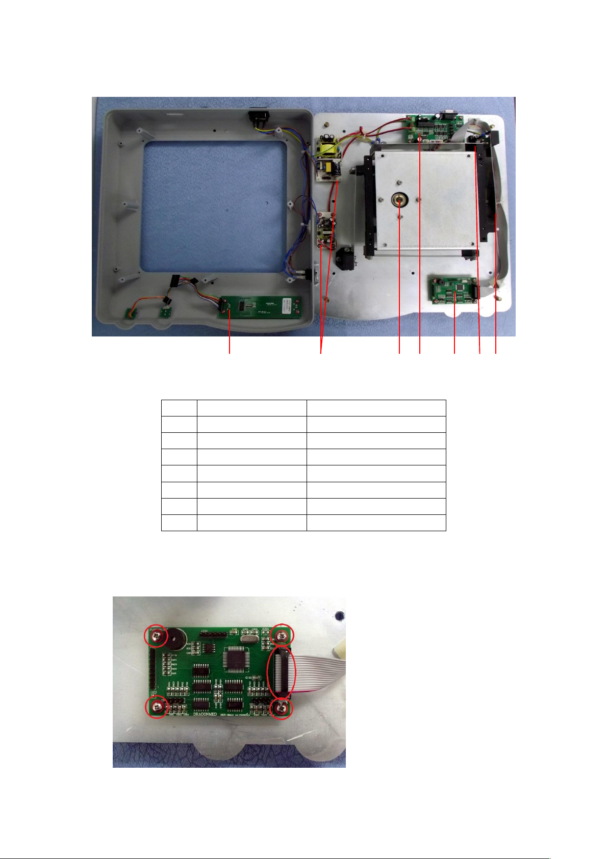
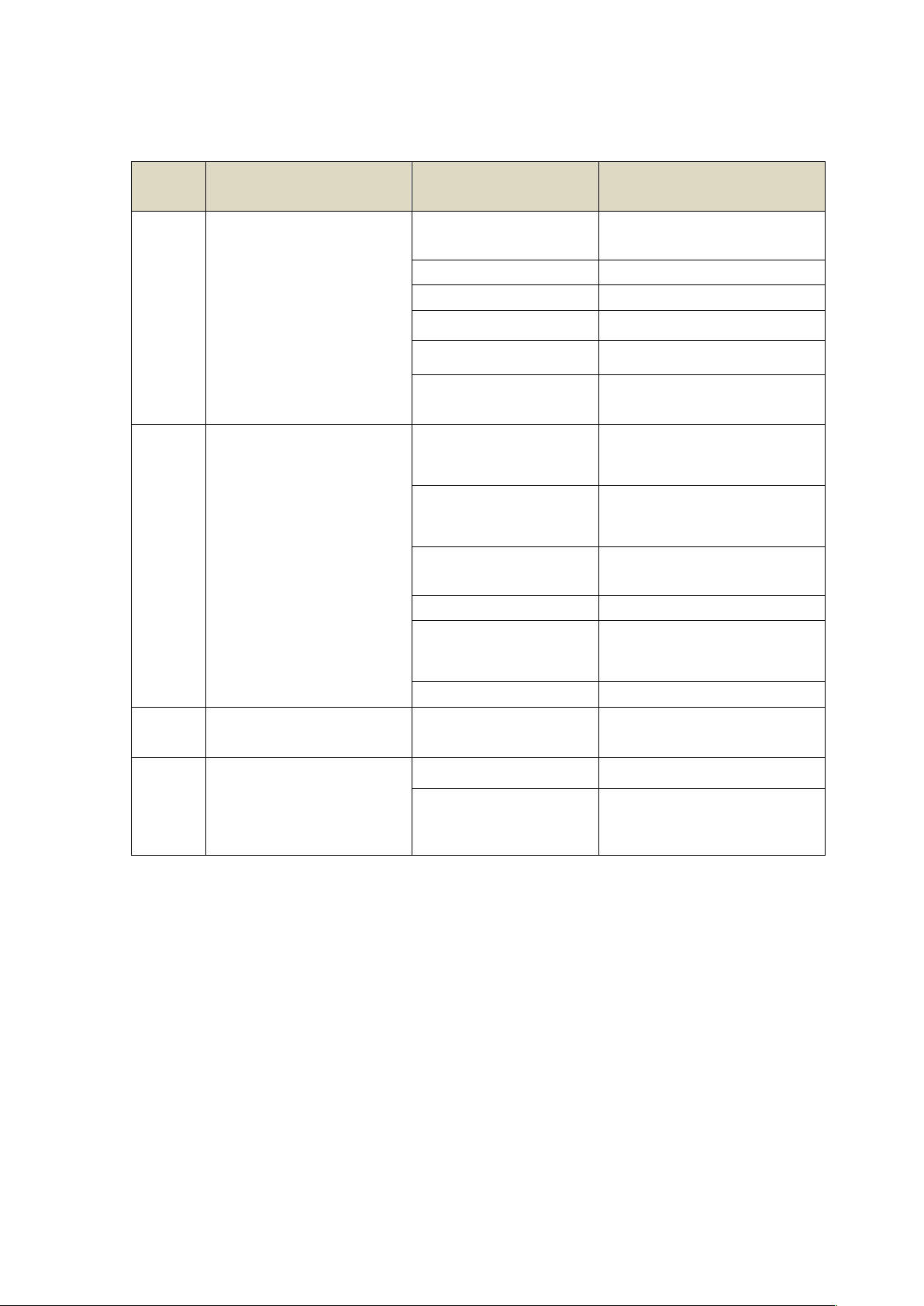
DLab SK-O330-Pro User manual

Shakers
SK-O330-Pro LCD Digital Orbital Shaker
SK-L330-Pro LCD Digital Linear Shaker
VERSION20170311

CONTENTS
Chapter 1: Working Principle ......................................................................................................... 1
1.1 Introduction ........................................................................................................................ 1
1.2 Composition ........................................................................................................................ 2
Chapter 2: Removal and Installation of Instrument ....................................................................... 3
2.1 Removal ........................................................................................................................ 3
2.2 Main parts illustration ................................................................................................... 5
2.3 Replacement of master control board .......................................................................... 5
Chapter 3: Trouble shooting........................................................................................................... 8
Chapter 4: Test Method .................................................................................................................... 9

1
Chapter 1: Working Principle
1.1 Introduction
1 2 3 4 5 6
FIG.1
Item 1 2 3 4 5 6
Function
Power
Switch
Rocker
Plate
Speed
Display
Time
Display
Speed Control
Knob
Timer Control
Knob
Shaker carries an object to conduct linear or circular motion at different speeds, and then mix
the material.
Fig. 1 is the schematic diagram of Shaker SK-O/L330-Pro. There are Speed display, Time
display, speed control knob, and timer knob on instrument control panel; power switch, on
the side of instrument; After properly connect the power cord and turn on power switch,
users set experimental conditions on the control panel by speed control knob and timer
knob, and real-time observe parameters setting values and actual values on screen.

2
1.2 Composition
FIG.2
1 Holding Bracket
2 Upper Guard
Module
3 Base Module
4 Motor Module
5 Rocker Module
FIG.3
Fig. 2 illustrates the separated structural components of SK-O330-Pro, and Fig. 3 is the Exploded
View of SK-O330-Pro. Base Modules include Base, Power Board, Master Control Board, Driver

3
PCB etc.; Motor Modules: motor, Counterweight, Support, Eccentric Axis, Bearing, Turnplate etc.;
Rocker Module: Rocker Plate, Rocker Panel, Shrapnel, Bracket etc.; Upper Guard Module: Upper
Guard, LCD PCB, Knob etc.
Power supply: 220/110V → power outlets → PCB → system control power supply
Movement: motor drives Movement Module to rotate. According to a different lock screw
location on Rocker Plate, the movement pattern of shaker is different.
Speed feedback: the motor speed is accurately measured by the Shaft Encoder fixed on the
motor along with photoelectric switch and a feedback is given.
LCD display: LCD PCB is connected to Master Control Board and displays user’s settings
and current equipment operation information.
Chapter 2: Removal and Installation of Instrument
When instrument failure occurs, first, you should conduct a failure analysis; if the failure is caused
by the damage of instrument hardware, the related component must be repaired or replaced. Here
are the relevant contents of the replacement and disassembly of instrument.
2.1 Removal
Tool:Cross screwdriver, Diagonal Pliers, Allen key, socket spanner
Step 1:
Turn the instrument upside down,
remove the screws at the red circle
icon;

4
Step 2:
Remove the screws marked by red
circles for retention (SK-O330-Pro).
For linear shaker (SK-L330-Pro),
remove the screws marked by green
circles for retention;
Step 3:
Lift the Upper Guard from the right,
and pull out 3 ribbon cables at the
red ellipse icon;
Step 4:
Turn the Upper Guard upside down
as shown in the Figure, and place it
on the clean desktop. The places
marked by the red circles are the
positions of pillar cushion of
circular shaker (SK-O330-Pro); The
places marked by the green circles
are the positions of pillar cushion of
linear shaker (SK-O330-Pro);

5
2.2 Main parts illustration
1 2 3 4 5 6 7
Item
Spare Parts Part number
1 Display board 18101126
2 Power board 18101661
3 motor 18100311
4 Drive board 18100313
5 Master control board 18101717
6 Shrapnel 2 18201095
7 Shrapnel 1 18201096
2.3 Replacement of master control board
Step 1:
As shown in the left figure,
remove the 4 screws and keep
them well, unplug the connector,
then replace a new master control
board, assemble in sequence.

6
2.4 Replacement of motor component
Step 1:
As shown in the left figure,
remove the 3 screws marked by
red circle, remove 3 screws in
the symmetrical side and keep
them well.
Step 2:
Remove the 4 screws marked by
red circles and keep them well,
take down shaker frame.
Step 3:
Take down belt, as shown in the
left figure, remove the 4 screws
marked by red circle, then
replace motor component.

7
2.5 Replacement of photoelectronic switch
Step 1:
Unplug the cable marked by red
circles on MS-Motro Board, as shown
in figure;
Step 2:
When you replaced new
photoelectronic switch, the Shaft
Encoder on the motor must match
with photoelectronic switch. When
motor is turning, Shaft Encoder
cannot be frictional contact with
Photoelectronic. After Shaft Encoder
is in place, lock it with screws.
2.6 Replacement of power board component
As shown in the left figure, unplug
the connector marked by blue
circles, remove the 8 screws marked
by red circle and keep them well,
then replace new power board
component.
2.7 Replacement of motor drive board
As shown in the left figure, unplug
connectors marked by blue circles,
remove the 4 screws marked by red
circles and keep them well, then
replace a new motor drive board.

8
Chapter 3: Trouble shooting
FAULT
CODE
PROBLEM CAUSE SOLUTION
E01
Instruments can’t be power
on
The power line is
unplugged
Check whether the power line is
unplugged, an power on it again
The power switch put off Put on the power switch
The fuse is broken Replace the fuse
Power board is failure Replace power board
Main board is failure Replace mainbaord
The display screen is
broken
Replace display screen
E02 Instrument doesn’t
movement
No setting target
temperature
Set a target temperature, and
the temperature indicator is on.
The drive board is failure
Replace the drive board, please
reference chapter 2.5
24V power board is
failure
Replace power board
component
Motor is failure Replace motor
Check whether shrapnel
is broken
Replace shrapnel.
Belt is loosen or broken Replace belt
E03 LCD display garbled
characters
Display board is failure Replace display board
E04
Instrument speed is not
accurate
Self-test, TE1 Ref,TE2 Ref,
TE3 Ref--error
Photosensor is failure Replace heated lid
The position of
photosensor goes failure
Adjust the position of
photosensor

9
Chapter 4: Test Method
4.1 The instruments does not move
Step 2: Detection of moving parts
Visually inspect if the steel strip of
Bracket Module is broken. If no
problem, remove the Bracket Module
and visually inspect if the belt is loose or
out of position. After the motor is
powered on, examine whether it is
running, and the belt drives
counterweight to rotate. If Bracket
Module, belt, and counterweight has no
problem after visual inspection, you need
to replace the motor and MS-Motor
Board.
4.2 Instrument speed is not accurate
Step 1: Check Photosensor connections
Check if Photosensor is reliable
connection with and MS-
Step 2: Check Photosensor position
Check if Photosensor plate welding wire is
open circuit, and check whether the fixed
screws of Photosensor are loose. Adjust
Photosensor position and fix Photosensor.
If the problem remains unresolved, replace
Photosensor.
Belt
counterweight
This manual suits for next models
1
Table of contents
Other DLab Laboratory Equipment manuals

DLab
DLab OS40-Pro User manual

DLab
DLab Thermo Control H100-Pro User manual

DLab
DLab RE100-Pro User manual

DLab
DLab MS7-H550-S User manual

DLab
DLab D3024 User manual

DLab
DLab Liquid Handling HiPette User manual

DLab
DLab DM0506 User manual

DLab
DLab MS-H380-Pro User manual

DLab
DLab OS20-Pro User manual

DLab
DLab D2012 User manual
Popular Laboratory Equipment manuals by other brands

Sanyo
Sanyo MLS-3020U instruction manual

Dynisco
Dynisco ViscoIndicator Installation & service guide

Teledyne
Teledyne CombiFlash Rf user manual

IKA
IKA 20015943 operating instructions

Leica
Leica CV5030 Supplemental sheet for Instructions for Use

ChemoMetec
ChemoMetec NucleoCounter NC-250 Instrument User Guide