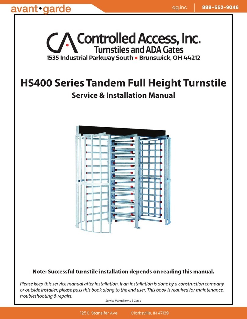
Controlled Access Tiffany T80-T User manual

Tiany T80-T Full Height Tandem Turnstile
Service & Installation Manual
Note: Successful turnstile installation depends on reading this manual.
Please keep this service manual after installation. If an installation is done by a construction company
or outside installer, please pass this book along to the end user. This book is required for maintenance,
troubleshooting & repairs.
Service Manual: 0740 E Gen. 3

Important Electrical Information
Installation of the control head mechanism into the turnstile requires a grounding-type
outlet receptacle installed inside of the frame or cabinet through the provided conduit
access points.
To reduce the risk of electric shock, this equipment has a grounding type plug that has a
third (grounding) pin. This plug will only t into a grounding type outlet. If the plug does
not t into the outlet, contact a qualied electrician to install the proper outlet. Do not
change this plug in any way.
Additionally, the P24-60W power supply from this appliance must be grounded to the
frame of the turnstile. Utilize the green colored grounding screw threaded into the
grouding tab located near the power supply along with the provided grounding wire
from the power supply to ensure the equipment is properly grounded.
T80-T Tandem Full Height Turnstile Service & Installation Manual
0740E Gen 3.
2

Table of Contents
Important Electrical Information 2
Model Datasheet 4
T80-T Fastener List 6
T80-T Components 7
T80-T Pre-installation Tips 8
T80-T Bearing Information 9
Mechanical Overview 10
Internal Parts Breakdown 11
Parts List 12
Control Head Congurations 13
Locking Bar Information 14
Hydraulic Shock & Indexing 16
Electrical Introduction 17
Wiring Diagram 18
Wiring Legend 19
Logic Controller Settings 20
Testing Procedure 21
Limit Switch & Limit Switch Cam Information 22
Maintenance & Cleaning 23
Troubleshooting 26
Proper Turnstile Usage 29
Warranty 30
Appendix
T80-T Tandem Full Height Turnstile Service & Installation Manual
0740E Gen 3.
3

PH: 330.273.6185 | Fax: 330.273.4468
Toll-Free Ph: 800.942.0829 | Toll-Free Fax: 800.942.0828
E-mail: [email protected]
The Leader in Pedestrian Access Control
0220
1535 Industrial Parkway South
Brunswick, Ohio 44212
www.controlledaccess.com
The Tiffany™ T80 Series T80-S | T80-T
Full-Height Turnstile |Interior & Exterior Application
The Tiffany™ T80-S Series (single, shown at right) and
the T80-T (tandem, shown below) are high security,
tamper-resistant, full-height turnstiles. Both variations are
manufactured with 6061/T6 anodized aluminum ovaline
arms and feature scratch-resistant polycarbonate yoke
assemblies for an open appearance. The T80 series is driven
by our reliable 6500 Series Control Head to accommodate
your security requirements.
Built in the USA
We’re the #1 Choice of Top Architects,
Security Pros and Engineers
For more than 30 years, Controlled Access has been the globally trusted
name in pedestrian control equipment. Made in Ohio and shipped
worldwide, we are the rst choice of leading architects, facility managers,
security consultants, and engineers. Whether your project requires high
security full-height turnstiles, waist high units, or matching ADA accessible
gates, Controlled Access is the secure choice. We’re experienced in
access control systems, from card readers to biometric scanning, to give
you the power to control access.
The T-80 series is also
available with integrated
metal detection portal
T80-T with
T36-ADA door

PH: 330.273.6185 | Fax: 330.273.4468
Toll-Free Ph: 800.942.0829 | Toll-Free Fax: 800.942.0828
E-mail: [email protected]
The Leader in Pedestrian Access Control
0220
1535 Industrial Parkway South
Brunswick, Ohio 44212
www.controlledaccess.com
Applications:
The Tiffany™ T80 Series is a three-vane turnstile
with a weather resistant nish and is ideal
for interior or exterior placement – whenever
style and durability are needed. It is crafted
from 6061 and 6063 aluminum extrusions
and features transparent scratch-resistant
polycarbonate yoke assemblies.
Product Features:
Materials & Finishes:
• Various 6061 & 6063 extruded aluminum
• 3/16" scratch-resistant polycarbonate
• Finish: Standard anodizing nish is clear. Also
available in dark bronze. Other colors can be
quoted upon request.
Assembly & Hardware:
• Major components pre-assembled with
concealed rods and spring pins
• Barrier and yokes secured with 3/4" rod
epoxied into concrete
• Rotor pivots on a sealed load runner bearing,
secured with high strength plastic coupling
anchored into concrete
• Minimum of 4” needed for removal of cover
Dimensions:
T80-S (Single)
•Ovaline Arms: 1/2" x 2" x 24"
•Exterior Height: 91" (2311.4mm)
•Interior Height: 84" (2133.6mm)
•Width: 66.250" (1682.7mm)
•Pedestrian Clearance: 27.750" (704.8mm)
T80-T (Tandem)
•Ovaline Arms: 1/2" x 2" x 24"
•Exterior Height: 91" (2311.4mm)
•Interior Height: 84" (2133.6mm)
•Width: 96.250" (2444.7mm)
•Pedestrian Clearance: 27.750" (704.8mm)
Operation Features
6500 Series Control Head:
• Auto-indexing (self-centering) with adjustable
hydraulic shock suppression
• Hardened tool steel locking bars, cam and
roller assemblies
• Permanently lubricated bearings
• Your choice of manual or electronic control on
both directions
• Nearly universal integration to any number of
access control systems
• Your choice on each electronic direction of
locking or unlocking on power failure
Options:
• Card reader mounting plates
• Daylight visible indicator lights
• Bi-directional key overrides
• 8 digit key resettable LCD counter with seven
year lithium battery
• Metal detection portal
• Cold weather package, including thermostat
controlled heater and insulated mainframe
• Additional options available upon request
* Dimensions are approximate
Warranty:
Units are warranted against
defects in materials and
workmanship for a period of
one year from date of delivery.
See warranty information for
specic details.
Electrical Specications:
Input Voltage: 100-240 VAC
Input Current: 1.3 - .55 A
Frequency: 50/60 Hz
Storage Temperature: -40 to 158°F
Operating Temperature: -4 to 131°F
Operating Voltage: 24VDC
Operating Current: 1.2 A (typical)
The 6500 Series Control Head
is certified to conform to the
following standards:
UL 294, UL 325, UL Subject 2593,
CAN/ULC S319 & CSA C22.2#247
4008027
The Tiffany™ T80 Series T80-S | T80-T
Full-Height Turnstile |Interior & Exterior Application
T80-T
Controlled Access, Inc. is certified
by Advantage International Registrar
to be an ISO 9001:2015 company
* Dimensions are subject to change without notice
T80-S

T-80-T FASTENER LIST
QTY 8 - 3/8 X 1 1/2 CAP SCREWS W/ NUTS:
CONTROL HEAD TO MAIN FRAME
QTY 4 - HOLLOW 3/4 RODS W/ NUTS AND WASHERS:
YOKE TO MAIN FRAME
(CARD READER SIDE OUTER MOST PART OF YOKE)
QTY 8- SOLID 3/4 RODS W/ NUTS AND WASHERS: YOKE TO
MAIN FRAME &BARRIER TO MAIN FRAME
QTY 2 - BAG OF EPOXY: RODS TO CONCRETE
QTY 6- 3/8 X 4 FLATHEAD EXPANSION ANCHOR W/ BEARING
BLOCK & BEARING: CENTER COLUMN MOUNTING
T80-T Tandem Full Height Turnstile Service & Installation Manual
0740E Gen 3.
6

T80-T Component Identification
Rotor A Rotor B Yoke Assembly (x4)
Barrier A Barrier B Mainframe
T80-T Tandem Full Height Turnstile Service & Installation Manual
0740E Gen 3.
7

T80-T Pre-installation Information
One of the main components of the model purcahsed is the mainframe assembly. This comes from the
factory pre-assembled.
Using the mainframe as a template, holes can be marked on the concrete for drilling the rods. The
product includes two types of rods: solid and hollow. Most holes receive solid rods, but hollow rods are
used to act as conduit for card reader wires.
The illustration below indicates which holes receive the solid and hollow rods.
The following page illustrates how the bearing assemblies for the rotor are installed.
T80-T Tandem Full Height Turnstile Service & Installation Manual
0740E Gen 3.
8

T80-T Tandem Full Height Turnstile Service & Installation Manual
0740E Gen 3.
9

6500 Series Control Head Mechanical Information
All of our turnstiles and ADA gates operate with a mechanism called the 6500 Series Control Head.
This sturdy and easy to maintain drive for the turnstile has replaced all previous model control heads.
It is adaptable to nearly any existing turnstile and comes with each new turnstile purchase. This control
head can be congured in multiple ways to accommodate the security requirements of each individual
job site.
An internal view of an electronically controlled two way 6500 series control head.
While the head can be congured for mechanical (no electronics) operation, a turnstile’s security
potential is reached in the case of an electronic two way control head. In this instance, each rotational
direction is independently unlocked. Congured properly, a control head will allow for one rotation
per valid entry request. Our anti-backup cams are designed so that it is mechanically impossible to
become trapped within the turnstile when properly installed.
Each control head comes precongured to your specic needs based o of a directional sheet that
is lled out before shipment. The heads are delivered pre-wired, tested and adjusted to our factory
recommendations. Installation is simple: connect inputs from access control devices into the logic
controller and plug the unit’s power supply into a 100-240 VAC (single phase) receptacle. The power
supply will automatically set itself to function on your local voltage and convert it to 24VDC.
T80-T Tandem Full Height Turnstile Service & Installation Manual
0740E Gen 3.
10

Phone: (800)942-0829
Fax: (800)942-0828
Web: www.controlledaccess.com
Email: sales@controlledaccess.com
Prices are subject to change without notice. Parts orders are shipped via FedEx. Shipping costs are not included. All parts orders under $500 require a credit card payment. Date: 04/01/2022
Complete control heads are
available upon request.
Contact us for pricing details.
Locking Bar Linkages
6519 - Fail Open
$12.26
6518 - Fail Lock
$12.26
Locking Bar Assemblies
0382 - Fail Open Assembly
$90.92
0383 - Fail Lock Assembly
$90.92
Limit Switch Cams
2267 - Standard $30.66
2268 - ADA $30.66
2269 - One-Way $30.66
Limit Switches
2180 - Standard
(Z-15GW2-B7-K) $22.68
1700 - One Way
(BZ2RW825-A2) $82.33
0372 - Top Casting
$219.65
0373 - Bottom Casting
$219.65
Control Head Castings
6532 - Index Pin
$132.69
Proximity Sensor & Accessories
7211 - 24VDC PNP Prox. Sensor
w/ M12 Connector (Sick 1040763)
$91.09
6589 - Turnstile Prox. Bracket
w/ 3x Mounts - LH, RH & Home
$11.19
0766 - 3 Branch M12 Splitter
$148.92
Shock Housing Assemblies
6535 - WH/427/430/T80/ADA
$189.18
6541 - 439/448/P60/HD
$198.68
Control Head Bearings
Indexing Springs
1106 - Waist High (Light) $6.51
1108 - Full Height (Heavy) $6.51
1107 - ADA (Extra Heavy) $6.51
Solenoid Springs
6510 - Fail Open Spring
$9.02
6016 - Fail Lock Spring
$9.02
6051 - Solenoid
Deltrol D4A53717-82
$65.55
Hydraulic Shock Absorbers
6560 - WH/427/430/T80/ADA
$190.75
6561 - 439/448/P60/HD
$346.47
0381 - Locking Bar Casting
w/ Oil Impregnated Bushings
$43.76
6520 - Index Pin Tubing
$32.99
0740 - Logic Controller (XD10)
$281.34
1641 - 1” ID for HS-22/439/448/P60
/RD70/Pre 2018 Top Castings
(1641-2RSNR) $7.39
7208 - Bottom casting on all models
(6007RSNR) $6.14
1640 - 7/8” ID for WH/ADA/T80 and
7/8” hex cams sold after 2018
(1640-2RSNR) $5.89
0751 - 24VDC Power Supply (60 W)
w/ NEMA 5-15 Drop Cord
$183.85
I1
A B OKESC
I2 IB IC ID IE
+
+
–
–
01 02 03 04
XD10
ML60
Power Supply
24V 2.5A
MiniLine
AC 100-240V
+ -+ -
N L
DC on
24-28V
Cam Assemblies
0401 - T80/WH/Legacy 427/430
(7/8 Hex Shaft) $264.26
0407 - P60 & RD70 Models
(1.25" Hex, Long) $291.95
0402 - ADA w/ Arm Adaptor $264.26
0416 - ADA w/ Chain Drive
0415 - All HS-22 Models/439/448/HD
(1.25" Hex, Short) $278.26
$278.26

6500 Series Control Head Congurations
The 6500 Series Control Head can be congured in a number of dierent ways. All units
operating with the 6500 Series Control Head self-center with a spring driven indexing pin
and hydraulically shock to the home position to prevent damage or injury.
Various congurations are available to suit the needs of any environment. These include:
Manual both ways: Unit rotates freely in both directions. This unsecure conguration is used
as a means to direct trac through one area. Full height turnstiles can be also be purchased
with an out of service lockout bar which would allow the end user to lock the turnstile with a
standard pad lock.
Manual one way: Turnstile rotates in one direction but not the other. This is often used for
egress only areas.
Electronic one way with free exit: Unit rotates freely in one direction but requires some
form of access control in the other. This is a typical installation in many facilities that want
to control who is entering but want egress to be free owing.
Electronic one way with no exit: Turnstile is locked in both directions at all times, but in one
direction can be unlocked with access control. Typically, this would be installed in scenarios
where there is an alternate means of exiting the facility.
Electronic two way: Turnstile requires access control for both entering and exiting a facility.
This conguration oers the highest level of security and also exibility for installations.
Fail lock: Upon power failure, an electronically controlled direction would remain locked.
This oers a high level of security but typically is not a good idea for egress unless alternate
methods of exiting are available. Unless equipped with key overrides, this is can be easily
converted to fail open by ordering alternate parts. This is also known as fail secure.
Fail open: Upon power failure, an electronically controlled direction would remain open.
This is the most common conguration as it allows for secure access controlled passage in
normal situations but in power outages it free wheels. Unless equipped with key overrides,
this can be easily converted to fail lock by ordering alternate parts. This is also known as fail
safe.
Key overrides: This option is available on either electronic or manual two way models. It
can allow for a quick reconguration of free owing passage or locking in either direction.
The key override option is not intended for constant every day use. Should you require an
additional lock-down feature on your turnstile, a better option (on a full height turnstile) is
an out of service lockout with a standard pad lock. Note that the key override option makes
conversion between fail lock and fail open very dicult to accomplish and also may not be
available for some turnstile or gate models.
T80-T Tandem Full Height Turnstile Service & Installation Manual
0740E Gen 3.
13

6500 Series Control Head Locking Bar Information
The 6500 Series Control Head is built to order based on a direction set up sheet sent with
each quote. This sheet denes how each direction of passage functions.
Direction 1 is dened as clockwise rotation on a full height or with the cabinet on the right for
waist high. Direction 2 is dened as counter-clockwise rotation on a full height or with the
cabinet on the left for waist high.
Possible congurations include: no passage, free passage (manual), fail lock and fail open. Fail
lock and fail open are not eld reversible without additional components.
“No passage” directions include a fail lock locking bar assembly as well as an unwired solenoid.
This adds the appropriate parts to the control head to prevent it from rotating in that direction.
“Free passage”(or manual) directions remove the solenoid and locking bar assembly, allowing
the cam to spin freely.
Each direction has a pair of holes on the locking bar and control head casting. These holes
act as pivot points for the locking bar casting. The inner holes are fail lock and outer holes
are fail open. A .5“ dowel pin slides through the entire assembly to hold everything in place.
Alternate linkages and springs are needed to convert a direction’s power failure status.
If optional key overrides are included, it becomes much more dicult to re-arrange the
conguration. Typically it is best to send the control head into the factory to recongure
any key override equipped head to ensure everything is done correctly.
Direction 1 Solenoid
Direction 2 Solenoid
Fail Open
Pivot Point
Fail Lock
Pivot Point
Fail Lock
Pivot Point
Fail Open
Pivot Point
Fail Lock
Pivot Point
Fail Open
Pivot Point
0381
Locking Bar Casting
Hardened 4140 tool steel
casting w/ oil impregnated
bronze bushings.
T80-T Tandem Full Height Turnstile Service & Installation Manual
0740E Gen 3.
14

The 6500 Series Control Head can be recongured from fail lock to fail open and vice versa.
Extra components are required to do so.
If a control head has key overrides, we suggest sending it in for factory reconguration.
Locking bar assemblies are held together with 1/8”spring pins. Extracting these pins and
reinstalling them can be tricky, so for convenience we also oer entire locking bar assemblies.
Replacing an entire locking bar assembly is simple; punch the .5” dowel pin from the pivot
point through the head casting (via a small hole in the bottom casting for this purpose),
pull out the old locking bar assembly and replace it with the new one.
If changing from fail lock to fail open or vice versa, install the dowel pin in the alternate hole.
6500 Series Control Head Locking Bar Information (Continued)
6519
Fail Open Linkage
These have an approximate
length of 2.5” and do not
have the extra hole for the
key override option.
6510
Fail Open Solenoid Spring
These look similar to fail lock,
but are actually stronger in force.
Wire diameter is .041”.
6518
Fail Lock Linkage
These have an approximate
length of 2.25” and also
include an extra hole the
key override option.
6010
Fail Lock Solenoid Spring
These look the same as the fail open,
but are actually lighter in force
Wire diameter is .032”.
This spring was also used
on the 6100 Series Control Head.
0383
Fail Lock Locking Bar Assembly
Includes locking bar casting
w/ oil impregnated bushings,
solenoid spring, locking bar
linkage, and solenoid plunger.
0382
Fail Open Locking Bar Assembly
Includes locking bar casting
w/ oil impregnated bushings,
solenoid spring, locking bar
linkage, and solenoid plunger.
Locking Bar Linkage
Spring Alignment Tabs
Solenoid Spring
Correct Alignment Incorrect Alignment
Make sure the solenoid spring is between the alignment tabs on the linkage or the
assembly may bind when pivoting.
T80-T Tandem Full Height Turnstile Service & Installation Manual
0740E Gen 3.
15

6500 Series Control Head Hydraulic Shock Information
The 6500 Series Control Head utilizes a spring loaded index pin for auto-centering the cam
while a hydraulic shock oers counter resistance to slow the rotation down.
Set properly, the shock will allow a turnstile or gate to self-center while rotating smoothly
without slamming.
Some turnstile models use a dierent shock than others. Waist highs and smaller full heights
use a .75” diameter shock while larger full heights use a 1” diameter shock.
Hydraulic ShockIndex Pin
3/4” Hydraulic Shocks:
Setting:
Loosen the set screw on the head of the dial
and turn the knob. The dial can be set
between 0 and 8. The higher the number, the
stronger the shock is. Tightening the set screw
can alter the shock strength so a good habit is
to loosen the set screw, turn the dial, tighten
the set screw then test your setting. Repeat
until satised.
Replacement:
Thread the new shock into the shock housing
as far as it will turn while the cam is in the
home position. Once it bottoms out, thread
the shock back out 1.5 - 2 turns until the
numbers on the dial are facing upright. Some
models may require an additional turn or two
outward if the arm does not self center on
even the lowest setting.
1” Hydraulic Shocks:
Setting:
Loosen the set screw on the head of the dial
and turn the knob. The dial can be set
between 0 and 8. The higher the number, the
stronger the shock is. Tightening the set screw
can alter the shock strength so a good habit is
to loosen the set screw, turn the dial, tighten
the set screw then test your setting. Repeat
until satised.
Replacement:
Thread the new shock into the housing as far
as it will turn while the cam is in the home
position. Once it bottoms out, thread the
shock back out 1.5-2 turns until the set screw
pointer is facing upright. Fasten the shock into
the housing by snugging the 1/4-28 set screw
into the bronze housing (snugly, but do not
over tighten or the brass might start to tare).
Failure to turn the shock back out after threading it in all of the way will likely cause the part
to wear out very quickly.
T80-T Tandem Full Height Turnstile Service & Installation Manual
0740E Gen 3.
16

6500 Series Control Head Electrical Information
Each electronic control head comes with a power supply, a programmable logic controller (PLC), limit
switches (or optionally, proximity sensors) and solenoids. For safety purposes, it is recommended that
you read all literature on the electrical components before attempting to install the control head into
a turnstile.
The 6500 Series Control Head is on the third generation of electronic components. The new XD10 logic
controller is a direct replacement of both the 0789 control board and 6789 (Keyence KV-16DR) logic
controller.
The latest enhancements provide a broader temperature range for outdoor installations (-4 to 131F)
as well as a user friendly text based interface with a daylight visible display. With this also comes
some new features such as on board testing buttons, turnstile statistics / information, etc.
While the wiring may be dierent, there are very few exceptions to when this board is compatible
with installed products. If an installation has the old 0789 circuit board (PCB) and has the optional
proximity sensor upgrade, new proximity sensors will need to be purchased. This is because the
0789 board had NPN inputs while the XD10 (and the KV-16DR) have PNP inputs.
The new PLC still requires relay contact closures for inputs just like all previous generations, so any
installation is compatible in one way or another. If assistance is needed with understanding how
to convert the wiring from access control to the new logic controller, please view this manual or
call our technical support department for assistance.
I1
A B OKESC
I2 IB IC ID IE
+
+
–
–
01 02 03 04
XD10
Inputs
To activate, apply local 24VDC + to desired input terminal.
Full Height Models:
Dir 1 - Clockwise
Dir 2 - Counter Clockwise
+
24
VDC
-
24
VDC
I1
Dir 1
Input
I2
Dir 2
Input
IB
Dir 1
OR
IC
Dir 2
OR
ID
Dir 1
Limit
IE
Dir 2
Limit Waist High Models:
Dir 1 - Right Hand
Dir 2 - Left Hand
Web: www.controlledaccess.com
Ph: (800)942-0829 Outputs
Dir 1 Fail Lock
Dir 1 Green Light
01
Dir 1 Fail Open
Dir 1 Red Light
02
Dir 2 Fail Lock
Dir 2 Green Light
03
Dir 2 Fail Open
Dir 2 Red Light
04
XD10 Logic Controller
0740
KV-16DR Logic Controller
6789
Control Board
0789
Lower Row Ports:
To 24VDC- | Lim 1 Inp | Lim 2 Inp | Unused | Unused | Fire Alarm Inp
Upper Row Ports:
Dir 1 Inp | Dir 2 Inp | Dir 1 OR Inp | Dir 2 OR Inp | Unused
Connect access control relays to 24VDC+ and desired input
Upper Row Ports:
Unused | Dir 1 Sol | Dir 2 Sol | Dir 1 Lt Red | Dir 1 Lt Green
Lower Row Ports:
24VDC+ | 24VDC- | Rly Com | Rly Com | Dir 2 Lt Red | Dir 2 Lt Green
Dir 1 = CW on FH, RH on WH/ADA | Dir 2 = CCW on FH, LH on WH/ADA
T80-T Tandem Full Height Turnstile Service & Installation Manual
0740E Gen 3.
17

5/28/2020
The 6500 series control head is
certied to conform to the following
standards: UL Standard 326,
UL Subject 2593 and
CSA Standard C22.2 #247
4008027
6500 Series Control Head w/ XD10 Controller Standard Wiring Diagram
Direction 1
Access Control Relay
N.O.COM
Direction 2
Access Control Relay
N.O.COM
Direction 1
Override Relay
N.O.COM
Direction 2
Override Relay
N.O.COM
Direction 1
Solenoid
Deltrol
D4A 53717-82
Direction 2
Solenoid
Deltrol
D4A 53717-82
COM
N.O.
N.C.
Limit Switch 2
Omron
Z-15GW2-B7-K
COM
N.O.
N.C.
Limit Switch 1
Omron
Z-15GW2-B7-K
Input Voltage:
100-240 VAC
1 Phase
1.1 - .6A Max
50/60 Hz
I1
A B OKESC
I2 IB IC ID IE
+
+
–
–
XD10
01 02 03 04
(Optional)
Direction 1
LED Indicator Light
(Tri-color, day light visible)
Banner Engineering
S18DLGRYPQ
(Optional)
Direction 2
LED Indicator Light
(Tri-color, day light visible)
Banner Engineering
S18DLGRYPQ
Black
Black
Brown
Brown
Blue Blue
White (not used) White (not used)
if Dir 1 is fail lock...
if Dir 1 is fail open...
if Dir 2 is fail lock...
if Dir 2 is fail open...
ML60.242
Power Supply
24V 2.5A
MiniLine
AC 100-240V
+ -+ -
N L
DC on
24-28V
Grounding Tab
in Cabinet or
Mainframe

Input descriptions:
24VDC + Positive output from the 24VDC power supply connects here.
24VDC - Negative output from the 24VDC power supply connects here.
I1 - Direction 1 Input - Unlocks direction 1 for either one rotation or until the timer expires. Standard access control should terminate here.
I2 - Direction 2 Input - Unlocks direction 2 for either one rotation or until the timer expires. Standard access control should terminate here.
IB - Direction 1 Override - Holds direction 1 unlocked for duration of contact closure. Mainly for re alarms and other temporary overrides.
IC - Direction 2 Override - Holds direction 2 unlocked for duration of contact closure. Mainly for re alarms and other temporary overrides.
ID - Limit 1 Input - Cancels Direction 1 activation if triggered before timer expires, re-locking the unit after one rotation.
IE - Limit 2 Input - Cancels Direction 2 activation if triggered before timer expires, re-locking the unit after one rotation.
Output descriptions:
All 4 relay outputs have individual commons. 24VDC+ is distributed to each relay common to operate the turnstile. It is OK to add extra wires
to these relay commons to distribute voltage to other devices.
01 - Output 1 - Dual purpose output for Direction 1. If the direction is fail lock, it’s solenoid would connect here. If equipped with an
indicator light, the green leg would connect here. Output switches from OFF to ON when directional input is triggered.
02 - Output 2 - Dual purpose output for Direction 1. If the direction is fail open, it’s solenoid would connect here. If equipped with an
indicator light, the red leg would connect here. Output switches from ON to OFF when directional input is triggered.
03 - Output 3 - Dual purpose output for Direction 2. If the direction is fail lock, it’s solenoid would connect here. If equipped with an
indicator light, the green leg would connect here. Output switches from OFF to ON when directional input is triggered.
04 - Output 4 - Dual purpose output for Direction 2. If the direction is fail open, it’s solenoid would connect here. If equipped with an
indicator light, the red leg would connect here. Output switches from ON to OFF when directional input is triggered.
Indicator light information:
Green Light - An indicator to inform pedestrians that they are allowed to pass through the unit. Uses black output wire from light’s cable.
Red Light - An indicator to inform pedestrians that the unit is locked or that pedestrians require credentials to enter. Uses brown output wire
from light’s cable.
As a side note, indicator lights purchased from Controlled Access, Inc. can also be wired to glow yellow. If desired, this can be used instead
of red with the unused white wire on the light’s cable to indicate to pedestrians they require credentials to enter. This is especially handy for
multi-lane installations in which some directions are “no passage” instead of “controlled passage”. Likewise, green lights can also be wired to
a red light output to constantly glow green to indicate“free passage”.
I1
A B OKESC
I2 IB IC ID IE
+
+
–
–
01 02 03 04
XD10
Inputs
To activate, apply local 24VDC + to desired input terminal.
Full Height Models:
Dir 1 - Clockwise
Dir 2 - Counter Clockwise
+
24
VDC
-
24
VDC
I1
Dir 1
Input
I2
Dir 2
Input
IB
Dir 1
OR
IC
Dir 2
OR
ID
Dir 1
Limit
IE
Dir 2
Limit Waist High Models:
Dir 1 - Right Hand
Dir 2 - Left Hand
Web: www.controlledaccess.com
Ph: (800)942-0829 Outputs
Dir 1 Fail Lock
Dir 1 Green Light
01
Dir 1 Fail Open
Dir 1 Red Light
02
Dir 2 Fail Lock
Dir 2 Green Light
03
Dir 2 Fail Open
Dir 2 Red Light
04
General denitions:
Direction 1 - Clockwise on full height turnstiles or cabinet on right for waist high
turnstiles & ADA gates.
Direction 2 - Counter clockwise on full height turnstiles or cabinet on left for waist
high turnstiles & ADA gates.
Limit - A switch or sensor designed to detect rotation and lock the unit after a rotation.
Fail Lock - Upon power failure, the direction is designed to remain locked.
Also known as Fail Secure.
Fail Open - Upon power failure, the direction is designed to remain opened.
Also known as Fail Safe.
Each unit is built to order, precongured to function as specied at the time the order
is placed. Some or all of the information listed may not be relevant to the installation.
Inputs are triggered with local 24VDC + (also known as PNP or sourcing).
Connect relay output from access control device to turnstile by terminating 24VDC +
to relay common and the desired input to the relay’s normally open terminal.
Be sure to disconnect power before wiring the board for safety.
Note: directional status outputs (lights) are unaected by optional key overrides as the
override occurs outside of the logic controller.
6500 Series Control Head w/ XD10 Controller Standard Wiring Legend
T80-T Tandem Full Height Turnstile Service & Installation Manual
0740E Gen 3.
19

6500 Series Control Head w/ XD10 Controller Standard Turnstile Settings
The XD10 logic controller on the 6500 Series Control Head has a text based menu screen to
adjust settings and view statistics of the turnstile. Pressing the A button will cycle to each of the
screens available on the device. Pressing B from any screen listed will return to the Home Screen.
Home Screen Timer Values Screen One-Shot Timers Screen
Swipe Queue Screen Direction 1 Counts Screen Direction 2 Counts Screen
General Info Screen
This screen is at the start of the
menu cycle. The top section will
give a read out of inputs that are
currently receiving voltage. The
display will return to this screen
after cycling through all windows,
5 minutes of inactivity or pressing
the B button.
This screen allows for the each
directional timer to be modied.
Select which value you wish to
edit by pressing the + & - key.
Press OK to select the value then
press + or - to modify. Save by
pressing the OK button again.
Each timer can have a value of 1 -
60 seconds. The timer will be
canceled upon rotation of unit.
This screen allows for the two
one-shot timer settings to be
enabled or disabled. This setting
prevents access control from
holding open a direction on the
standard direction inputs. Toggle
Direction 1 by pressing + and
Direction 2 by pressing -. This
should be set to “On”in almost
every installation.
This screen denes the maximum
number of access control requests
the unit will allow in queue. Each
value can be set from between 1
(for maximum security) to 3 (for
fast paced passage). The default is
2. The method to change these
settings is the same as the Timer
Values Screen.
This screen gives statistics about
how many times direction 1 was
activated and cycled. Since there
is a limit to how many counts can
be displayed, after 25000 cycles
the rst counter resets and adds
to the second counter.
This screen gives statistics about
how many times direction 2 was
activated and cycled. Since there
is a limit to how many counts can
be displayed, after 25000 cycles
the rst counter resets and adds
to the second counter.
Factory Setup Screen
This screen should only appear
when rst set up in the factory or
if something occurs to totally reset
the logic controller. If this
manages to occur and the order
number (if known), enter it as a
value then press B to save.
This screen displays when the PLC
was initiated, the order number it
was activated for (except for any
revision suxes which are not
needed for order lookup), and the
PLC software version.
Testing Mode Screen
While this screen is active, the unit
can be tested with push buttons
to simulate access control inputs.
See the page dedicated to testing
for more information.
T80-T Tandem Full Height Turnstile Service & Installation Manual
0740E Gen 3.
20
Table of contents
Other Controlled Access Turnstile manuals