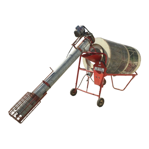
DMC Hi Cap 54 User manual

OWNER’S MANUAL
Hi Cap 54
Grain Cleaner
PNEG-1147
PNEG-1147
Date: 3-1-02

SAFETY INFORMATION
PLEASE READ
WATCH FOR THIS SYMBOL! IT POINTS OUT IMPORTANT
SAFETY PRECAUTIONS. IT MEANS, “ATTENTION -
BECOME ALERT! YOUR SAFETY IS INVOLVED!”
It is recommended that you review the entire contents
of this manual, paying particular attention to items
preceded by this symbol. FAILURE TO HEED THESE
INSTRUCTIONS CAN RESULT IN PERSONAL INJURY!
Operation of this farmstead equipment shall be limited to competent
and experienced persons. In addition, anyone who will operate or work
around power equipment must use good common sense. In order to be
qualified, he or she must also know and meet all other requirements,
such as:
1) Some regulations specify that no one under the age of 16 may
operate power machinery. This includes farmstead equipment.
It is your responsibility to know what these regulations are in your
own area or situation.
2) Current OSHA regulations state in part: “At the time of initial
assignment and at least annually thereafter, the employer shall
instruct every employee in the safe operation and servicing of all
equipment with which the employee is, or will be involved.” *
3) Unqualified persons are to stay out of the work area. The “Work
Area” is defined as any area where this equipment is installed.
4) A person who has not read and understood all operating and
safety instructions is not qualified to operate the machine.
* Federal Occupational Safety & Health Standards for Agriculture
Subpart D, Section 1928.57 (a)(6).
OPERATOR QUALIFICATIONS

BE A SAFE OPERATOR
1) Read and understand the Owner’s Manual.
2) Keep all safety shields in place.
3) Do not wear loose-fitting clothing while working with equipment in
operation.
4) Keep hands and feet away from moving parts. Be sure all people
are clear of the equipment before start-up.
5) Disconnect all electrical power before servicing, adjusting, or
lubricating the equipment.
6) All electrical hook-ups should be in accordance to the National
Electrical Code.
7) Ground all electrical equipment.
8) Towing speed for your Hi-Cap Cleaner should not exceed 45 miles
per hour. Atow chain should be used when on a public roadway.
9) Only knowledgeable and trained personnel should operate this
equipment.
FAILURE TO FOLLOW THESE INSTRUCTIONS
MAY RESULT IN PERSONAL INJURY OR
PROPERTY DAMAGE.
-ii-

SAFETY TOW CHAIN FOR 44 & 54 CLEANERS
P/N: 2051071
Two chain assemblies are provided to be used as safety chains whenever Models 44 & 54
Hi-Cap cleaners are towed. These pictures show the proper attachment of the chains to the
cleaner tongue. Each chain should be wrapped through and around the tongue handle before
being hooked to the rear of the handle. The other ends of the chains should be hooked to the
towing vehicle with enough slack to provide clearance when turning.
-iii-

THE DECALS SHOWN ON THIS PAGE MUST BE DISPLAYED AS SHOWN
REPLACEMENTS ARE AVAILABLE UPON REQUEST
Write to: DMC • 1004 E. Illinois St. • Assumption, IL 62510
Ph: 217-226-5100
Please note: 1) The decals on the page are not actual size
2) Keep decals wiped clean at all times.
3) Decals must be replaced if they are destroyed,
missing, painted over, or can no longer be read.
104L0014 202L0311 206L0007
205L0004
405L004
205L0011
-iv-

DAVID MANUFACTURING CO.
1600 12th Street NE
MASON CITY, IOWA50401
INTRODUCTION
Model 54 Hi-Cap Cleaner Assembly Instructions, Transport Model 1 - 21
10” x 12’ Auger Assembly Instructions 22 - 27
Attaching 10” Auger to Cleaner 28 - 29
Hydraulic System Information 30
Hydraulic Drive Assembly Instructions 31
Hydraulic Drive Installation 32 - 33
Model 54 Grain Cleaner Drum, Parts Breakdown 34 - 35
Model 54 Grain Cleaner Support Frame 1 and 2 36 - 37
Model 54 Grain Cleaner Support Frame Drawings 1 and 2 38 - 39
Model 54 Grain Cleaner, Parts List 40 - 42
Model 54 Grain Cleaner, Hydraulic Controls 43
10” x 12’ Feed-In Auger 44 - 45
Model 54 Hydraulic Grain Cleaner, 10” x 12’ Feed-In Auger 46 - 47
Electrical Wiring Diagram 48
Model 54 Cleaner Dimensions 49
Available Screens for the Model 54 Hi-Cap Grain Cleaner 50
Hi-Cap Cleaner Capacity Chart 51
WARRANTY 51
INDEX

INTRODUCTION
Congratulations! You made a very wise decision in purchasing a Model 54 Hi-Cap
Grain Cleaner. With its counter-rotating drums, it will remove more trash and “fines” per
bushel than other cleaner in its class. The Hi-Cap offers a wide range of screen sizes to
take care of all your screening needs. With its dual screening action, it not only removes
“fines”, chaff, etc., but also the large trash such as cob particles, straw and stalks. If
properly adjusted and maintained, your Model 54 Hi-Cap Grain Cleaner investment will
pay off for years to come.
To assure maximum belt life, the proper tension must be maintained. Check the
belts frequently during the operation of the Model 54 Hi-Cap Cleaner. If there is any
accumulated trash in the pulley grooves, it should be removed.
The outside cleaning drum should turn approximately 21 revolutions per minute,
and rotate clockwise, while the inside drum turns counter clockwise when viewed from the
feed-in end. The cleaner should be run until empty before stopping. It is not advisable to
leave grain in the cleaner or start the cleaner with a load of grain in it.
THEADJUSTABLE JACK-STAND PROVIDESTWO FUNCTIONS:
1) It enables you to hook the Model 54 to your prime mover very easily, and
2) it also serves as a leveling jack when the Hi-Cap is in working position. A small
level on the front main frame is standard equipment. It allows you to set your
Hi-Cap Grain Cleaner at its proper operating position regardless of terrain
conditions.
230-volt single-phase or three-phase power is required to operate your Model 54
Hi-Cap Cleaner. To avoid possible bodily injury or electrical shock, the customer must
provide fuse disconnect or equivalent groundedAC power.
Hydraulic Drive is also available for your Model 54 Hi-Cap Grain Cleaner.
When lifting 5” trash auger into operating position, a screwdriver may be needed
to assist in aligning the two sections of auger. Rotation of one section may be required,
should drive pins coincide.
The feed-in auger swing arm is designed
to hold the 10” auger from swinging while in
transport position. To swing into operating
position, simply lift drop pin and rotate a quarter
turn. This will lock the pin up for easy movement.
Once the auger is in operating position, the pin
can be turned and lowered so that the feed-in
auger will be kept in operating position.
DROP PIN
OPERATION
SERVICE

A variety of screens can be obtained to fit your needs. See Page 50.
If screens are not properly placed on the cleaner, grain can get behind the lap and
cause problems. The lap should also be over the tumbling bars. See Photo 39.
20 PSI will give your tires maximum tire life and yet provide flotation for your Hi-Cap
while being towed at highway speeds.
Towing speed should not exceed 45 miles per hour. When on a public road, use a
safety chain.
10” x 12’ auger with hopper and slide gate
5 HP auger motor
Screens to match your operation
3-phase electric power
Hydraulic drive
SCREENS
TIRE PRESSURE
TOWING SPEED
OPTIONAL EQUIPMENT

MODEL 54 HI-CAP GRAIN CLEANER
ASSEMBLY INSTRUCTIONS
TRANSPORT MODEL
COMPONENT PARTS AS SHIPPED MODEL 54 GRAIN CLEANER
0005 0032 0010
PART # #REQ #REQ #REQ DESCRIPTION
1. 206N0011 1 1 1 SHIPPING CRATE, (54), (CHART HC-12)
2. 206N0012 1 - - ACCESS. BOX(54), SINGLE PHASE(CHART HC-10)
206N0013 - 1 - ACCESS.BOX(54),THREEPHASE(CHARTHC-10)
206N0026 - - 1 ACCESS.BOX(54), HYDRAULIC,(CHARTHC-10)
3. 206N0014 1 1 1 SCREEN BOX, OUTSIDE,(54)(CHART HC-18)
4. 206N0015 1 1 1 SCREEN BOX, INSIDE,(54)(CHART HC-19)
5. 206A0055-D 1 1 1 DRUM BUNDLE ASSEMBLY (54)
6. 206N0041 2 2 2 TIRE MOUNTED ON WHEEL, NEW15”,4BOLT(HC-17)
7. 206E0010-C 1 - - 3 HP/SINGLE PHASE MOTOR W/ PULLEYS MOUNTED
206E0016-C - 1 - 3 HP/THREE PHASE MOTOR W/ PULLEYS MOUNTED
8. 206N0023 - - 1 AUGER BOX, 10” HYD. (CHARTHC-7)
(not shown)
9. 206N0040 - - 1 AUGER BUNDLE, (10” x 12”) (HC-6)
(not shown)
PROPER ASSEMBLY ASSURES BETTER OPERATION
1
2
34
5
6
7

Step 2. Turn axle over on level floor as
shown in Photo 2. Tighten bolts.
Step 3. Bolt wheels to hubs, using
eight 1/2” x 3/4” hub bolts.
TIGHTENSECURELY.
See Photo 3.
Step 4. Turn axle assembly with frame
supports upright and bolt side
channels to frame support,
using four 3/8” x 1” hex bolts,
lock washers and hex nuts.
A weld nut has been provided
on the base of the side frame
channel that set on top of the
axle frame support. Use two
3/8” x 1” hex bolts, and lock
washers in conjunction with
weld nut. NOTE: RIGHTAND
LEFT SIDE CHANNELS.
See Photos 4 and 5.
Photo 1 Photo 2
Photo 3
Photo 4
Step 1. Bolt axle frame supports to main axle assembly, using four 3/8” x 1” hex
bolts, lock washers and hex nuts. See Photo 1.
1

Step 5. When bolting the front frame assembly
to side channels, BE SURE FRAME
ENDS ARE EQUAL HEIGHT ON BOTH
SIDES. Secure with eight 3/8” x 1” hex
bolts, lock washers, and hex nuts.
Leave bolts loose.
Step 6. Bolt rear frame assembly to side chan-
nels, using four 3/8” x 1” hex head bolts,
lock washers and hex nuts. See Photo
6. Bolts are to remain loose at this point.
Step 7. Level and square main frame
assembly and tighten loose
bolts from Steps 5 and 6. See
Photo 7.
Step 8. Bolt front tongue and trash
pan bottom assembly into
position by placing pan
portion on axle and securing,
using two 3/8” x 1” carriage
bolts, SAE flat washers, lock
washers and hex nuts.
BOLTS MUST REMAIN
LOOSE AT THIS TIME. See
Photo 8.
Photo 6
Photo 5
Photo 7 Photo 8
2

Step 10. Bolt the jack assembly to the tongue assembly, using four 3/8” x 1” hex
bolts, lock washers and hex nuts. See Photo 10.
Next, bolt lower frame braces to axle assembly frame supports and front
tongue trash pan bottom, using six 3/8” x 1’hex bolts, 3/8” SAE flat washers,
lock washers, and hex nuts. BE SURE side channels are even and square.
See Photo 11.
Step 9. Bolt front brace extensions to front frame assembly and to trash pan bottom,
using six 3/8” x 5” hex bolts, lock washers and nuts. See Photos 9 and 10.
SECURE ALL LOOSE BOLTS FROM STEPS 8 AND 9.
Photo 9
Photo 10 Photo 11
3

Step 11. Trash pan assembly consists
of a left and right side panel
and two ends. Start by
positioning side panel as
shown in Photo 12.
NOTE: STRAIGHT END OF
PANELTOWARD FRONT.
Secure to cleaner side
channel. Secure to trash pan
bottom with 1/4” x 5/8” hex
flange screws and hex flange
lock nuts. DO NOTTIGHTEN
BOLTS OR PUT BOLTS IN
FIRST AND LAST HOLE.
Step 12. Bolt front end of trash pan
into position by placing end
panel lip under side panel,
using fourteen 1/4” x 5/8” hex
flange screws and hex flange
lock nuts. See Photo 13.
DO NOT TIGHTEN BOLTS
Step 13. Continue by bolting other half
of trash pan on to side rail and
trash pan bottom. Be sure side
panel lays on top of front panel
lip. Use seven 1/4” x 3/4” hex
bolts, flat washers, lock washers
and hex nuts, and ten 1/4” x 5/8”
hex flange screws and hex flange
lock nuts. OMIT BOTTOM BOLT
AT THE REAR. Do not tighten
bolts at this time.
Step 14. Install 10” trash pan auger
(ribbon flighting) with key-way
end of shaft installed into front
trash pan bearing. See Photo 14.
Step 15. Bolt rear panel of trash pan into
position, using twelve 1/4” x 5/8”
hex flange screws, hex flange
lock nuts. TIGHTENALL TRASH
PAN BOLTSAT THISTIME.
Photo 12
Photo 13
Photo 14
4

Photo 18
Photo 16
Photo 17
Photo 15
Step 16. Slide 10” ribbon auger into rear trash pan bearing. See Photo 15.
Step 17. Bolt three-horsepower motor to motor mount bracket using four 3/8” x 1-1/4”
hex bolts, lock washers and hex nuts. See Photo 16. For units equipped
with hydraulic drive, see separate instructions on page 31.
Step 18. Thread one 3/8” x 5-1/2” full-thread hex bolt into belt tightener angle about
4-1/2”. Then thread one 3/8” hex lock nut to the full-thread bolt
approximately 3/4”. Continue by placing motor and motor mount channel
to front brace. Secure with one 3/8” x 5” hex bolt. Do not tighten 5” bolt
at this time. Slide motor mount down front brace to the tightener bolt.
Finish by putting 3/8” lock nut to tightener bolt. See Photos 17 and 18.
Step 19. To install the main drive shaft, remove six 5/16” x 3/4” carriage bolts which
hold the bearing flanges together. Place shaft into “U” bearing support
brackets with single pulley to the rear. Using two 5/16” x 3/4” carriage bolts,
lock washers and hex nuts, bolt rear bearing so that the flanges are outside
of the bearing support. See Photo 19.
5

Step 20. Lift front end of drive shaft up
from brackets and place three
A-136 drum drive V-belts over
shaft. Then place two trash pan
auger drive belts (A-91) over the
two-groove pulley on the main
drive shaft located between the
bearings. Loosen the locking
collars holding the two front
bearings. Then bolt the bearing
flanges outside of the support
brackets using four 5/16” x 3/4”
carriage bolts, lock washers and
hex nuts. Finish by locking the
bearing collars in the direction of
the shaft rotation. Rotation would
be clockwise when viewed from
the front. See Photos 20 and 21.
Photo 19
Photo 20 Photo 21
Photo 22
Step 21. Install drum drive belt idler
assembly using one 5/8”
SAE flat washer and one
5/32” x 1” cotter pin. Attach
two extension springs to the
idler arm. See Photo 22.
6

Photo 23 Photo 24
Photo 25 Photo 26
Step 22. Fasten motor belt shield back panel, using two 1/4” x 3/4” self-tapping
screws. Have the flange facing toward front. Slotted holes are provided in
case adjustment of the panel is necessary when the front drive belt shield is
installed. See Photo 23.
Step 23. Install 16” double-groove front drive pulley using 1/4” x 2-1/4” square key.
Place pulley on the shaft with hub out. Shaft must be brought through pulley
approximately 1/8” to be in proper position. Check alignment with motor
pulley. Securely tighten set screws. See Photo 24.
Step 24. Install two A-66 drive belts between motor and 16” pulley, and adjust tension
to the point that the belt will have approximately 3/8” deflection. See Photo
25. BE SURE MOTOR PULLEYAND 16” PULLEY ARE PROPERLY
ALIGNED. TIGHTEN 3/8” X 5” BOLT HOLDING MOTOR MOUNT.
Step 25. Place 1” locking collar on to 10” ribbon auger shaft. Pull shaft through
bearing until 7-1/4” of shaft is protruding past the lock collar in direction
auger turns (clockwise). See Photo 26.
7

Step 26. BOLT, BUT DO NOTTIGHTEN, the adjusting plate with two 5/16” x 1” hex bolts,
5/16” flat washers, lock washer and hex nut. Position the lower bolt on the
opposite side of the 5” trash auger.
Step 27. Place the 28 tooth sprocket on the trash pan auger shaft using 1/4” x 1-1/4”
square key. Position sprocket, hub outward, so there is 2-3/8” distance from the
front mounting plate to the center of the sprocket teeth.
Step 28. Place 8” cast two-groove pulley on to trash pan auger shaft, using 1/4” x 2”
square key. Position pulley 4-5/8” from the front of the trash pan panel to the
center of the first groove from panel. Securely tighten set screws. Place the two
A-91 belts, installed in Step 20, over the trash pan auger shaft. See Photos 27
& 28.
Step 29. Bolt front switch box plate with 1” wood bearing for trash auger shaft into
position using four 1/4” x 5/8” flanged head screws and hex flanged lock nuts.
(Should wood bearing need alignment, bolts holding bearing may have to be
loosened) See Photo 28.
Step 30. Insert wire for three-horsepower motor through flared hole at lower end of front
brace extension. Push through center of tube and out the top. Connect to the
motor, using water-tight connector. Correct rotation is clockwise when looking at
motor shaft in mounted position.
Step 31. Bolt the 3-1/2” flanged idler pulley for
A-91 belts into position using 3/4”
spacer, 1/2” x 3” hex bolt, two flat
washers, lock washer and hex nut.
Place the 3/4” spacer between the
mounting bracket and pulley with one
flat washer on each side of adjust-
ment slot. Finish by putting the A-91
V-belts on to pulleys and tighten belts
to approximately 3/8” deflection. See
Photo 29. Check alignment of pulleys
and idler.
Photo 27 Photo 28
Photo 29 8

Step 32. Bolt V-belt idler pulley to rear frame position, using one 1/2” x 4-1/2” full-thread
hex bolt, two 1/2” flat washers, one 1/2” x 3/4” spacer bushing and lock
washers, and hex nuts. See Photo 30.
Step 33. Bolt on rear belt shield bracket, using two 5/16” x 3/4” hex bolts, lock washers
and hex nuts. Next, place 3/8” SAE washer and compression spring on rod
attached to idler arm. Put rod through shield bracket hole. Fasten the pulley
and idler bracket to the grain cleaner, using one 3/8” x 3” hex head bolt, and
3/8” lock nut. DO NOT OVERTIGHTEN. THE ARM AND PULLEYASSEMBLY
MUST SWING FREELY. See Photo 31.
The main component parts of the drum are shown in their respective position in Photo 32.
Step 34. Bolt the large, six-spoke cone ring to the disc on the shortest end of drum
axle, using three 3/8” x 1” hex bolts, lock washers and hex nuts.
See Photo 33.
DRUM SET-UP PROCEDURE
Photo 30
Photo 31
Photo 32 Photo 33
9

Step 35. Place the three flow rings over cone drum axle. Continue by bolting the small
cone ring to the drum axle using three 3/8” x 1” hex bolts with lock washers and
hex nuts. See Photo 34.
Step 36. Bolt six screen support bars to cone rings, using twelve 1/4” x 5/8” hex flange
screws and hex flange lock nuts. Bolt bars underneath cone ring flanges with
slotted end of bar attached to the small ring. Tighten securely. See Photo 35.
Step 37. To attach cone flow rings to the screen support bars, bolt angle bracket to
cone flow rings using shortest end of angle. Proceed to bolt cone flow rings to
the screen support bars with the longest end of the angle pointing toward inlet end
of drum. See Photo 36. The entire operation requires eighteen
1/4” x 5/8” flange head screws and flange lock nuts. See Photo 36.
BOLT CONE FLOW RINGS TO ALTERNATE SCREEN SUPPORT BAR. (See Photo 37)
Photo 34 Photo 35
Photo 36 Photo 37
10

Step 38. CONE SCREEN INSTRUCTIONS:
There are three sections of screen
for the cone and twenty-four #10 x
3/4” self-tapping washer-head
screws. Take one piece of screen
and attach to the screen support
bar. Wrap screen around drum,
taking second and third piece of
screen and continue process until
the cone is completely covered.
NOTE: Screens must be properly
lapped so that during operation,
grain will be forced between the
screen laps. See Drawing and
Photos 38-40.
Finish attaching cone screens by placing straps on each end of drum.
Secure with 1/4” x 2-1/2” bolt and 1/4” hex nuts.
DIRECTIONOFROTATION
As viewed from the small end
of cone drum.
Photo 40
Photo 41
Photo 39
Photo 38
11
Table of contents
Other DMC Ultrasonic Jewelry Cleaner manuals
