DODA BG80 Series User manual

1
USE AND MAINTENANCE MANUAL
MIXER FOR
BIOGAS
FERMENTERS
SERIES BG80
®
COSTRUZIONE MACCHINE AGRICOLE
di
DODA ALDO & C SNC
COSTRUZIONE MACCHINE AGRICOLE di DODA ALDO & C SNC
Via Sante Sal aso 18/20 46010 BUSCOLDO (MN) ITALY
Tel. +39 0376/410043 - Fax. +39 0376/410032

2
INDEX
1 EC Declaration of confor ity
2 Safety instructions
2.1 Allowed employment
2.2 Safety rules
2. Symbols present in the manual
2.4 Stickers
3 Description
4 Functioning
5 Technical features
5.1 Technical data
6 Installation
6.1 Mounting instructions
6.1.1 Mixer with roof mounting
6.1.2 Mixer with wall mounting
6.2 Mixer mounting and installation
6.2.1 General instructions
6.2.2 Mixer with roof mounting
6.2. Mixer with wall mounting
6. Electric connection
6. .1 Setting of the mixer operating interval
7 Setting in otion
7.1 Checks at the first setting in motion
7.2 Checks before each setting in motion / Daily checkings
7. Mixer functioning
8 Maintenance progra
8.1 Maintenance depending on wear level
8.2 Current maintenance
9 Spare part list

1 EC DECLARATION OF CONFORMITY
IN CONFORMITY WITH THE DIRECTIVE 89/ 92 EC
We
DODA di Doda Aldo & c. s.n.c.
Via Contrargine sud, 3/5
46010 Canicossa (Mantova)
hereby declare under our own responsibility that the equip ent, entioned below,
MIXER SERIE BG
confor s to the require ents of the EC Directives 98/37/CE (replacing the previous
one 89/392/CE) and 94/9/CE concerning equip ent intended for use in potentially
Explosive At ospheres (ATEX).
HARMONISED STANDARDS
DIN EN 982 DIN EN 1127-1
DIN EN 12100-1 DIN EN 12100-2
DIN EN 50014 DIN EN 50021
DIN EN 13463-1
The ixer is designed for bio ass ho ogenization, also in the presence of non-
ho ogeneous atter, and as a consequence is suitable for the installation on Biogas
fer enters , available with both wall and roof ounting fra e .
The here enclosed Declaration of confor ity is valid only if all instructions
reco ended with this anual are carefully followed.
The ixer arking includes the following labels:
EX II3GX
CANICOSSA (MANTOVA)
……................................................
(Na e, signature, corresponding)
Notes concerning the declaration of confor ity
The present declaration states that the machines are in conformity with the strict provisions of
the European Directive 98/ 7 CE.
However, please take into account that even though the safety rules are carefully followed,
the employment of each mixer implies certain risks.
Therefore, besides the general safety and accident prevention rules , we recommend that you
should follow the safety instructions indicated in the present manual and the ones suggested
by common sense.

4
2 SAFETY INSTRUCTIONS
2.1 Allowed e ploy ent
The BG80 mixer has to be employed only to homogenize biomass present in a digester or in
fermentation tanks , such as slurry, non-homogeneous matter and other co-ferments.
With our mixer it is not allowed to mix the following substances:
Mud obtained by clarification
Solid bulky matters
Bodies with sharp corners which could damage the mixer
Medium mixed with foreign bodies (strings, ropes, plastic tapes, etc..…)
An employment different from that herewith indicated is not allowed.
Therefore the user as well as the mixer owner will be held responsible for any damage caused
by an incorrect use.
For a correct employment:
- Follow the instructions of this manual;
- Respect the check and maintenance intervals indicated.
2.2 Safety rules
Follow the safety rules of the local authorities concerning Biogas plants, as well as the general
safety provisions and the accident prevention regulations.
We recommend that any repair should be carried out either by an authorized mechanic
assistance or by the manufacturer’s technical assistance department.
In case, functioning defects arise due to the non-compliance with the hereby given use and
maintenance instructions, the manufacturer could not be considered responsible.
2.3 Sy bols used in this anual
Warning! Danger!
This sign warns you about a possible danger and suggests the most correct way you
should behave in such situation.
Warning! Danger electricity!
This sign warns you about dangers that can cause damages to the mixers and to
other present equipments as well as environmental degradation.
Warning! Fla able and explosive at osphere!
The employment of the mixer in potentially explosive zones 0 and 1 can cause
damages to things and injuries to persons with danger of death!

5
2.4 Stickers
The mixer is provided with the following stickers:
Read the instruction manual!
Warning! Danger!
Warning! Flammable and explosive atmosphere!
PRIMA DELL’USO RIEMPIRE D’OLIO
FINO A LIVELLO
IMPORTANT: Before setting the achine
in otion, fill it up with oil till the
indicated level.
Fill up the achine with oi
l till the
indicated level.
Check periodically the oil level.
This sticker re inds you to check the
rotation direction of the electric otor
before setting the achine in otion.
DATA PLATE INDICATING THE
CONFORMITY WITH
EC REGULATIONS:
1) NAME OF THE COMPANY
2) MONTH/YEAR OF PRODUCTION
) SERIAL NUMBER
4) MACHINE TYPE
1
MARZO 2007 BG
80
2
4

6
3 DESCRIPTION
The BG80 mixer is specifically designed for biogas fermentation tanks, characterized by an
high dry matter content.
The mixer employment is aimed at preventing the development of settled and floating layers
in the tank.
To ensure an excellent mixing efficiency, the BG80 mixer is provided with an hydraulic device
for the regulation of the tilt angle of the propeller in the tank.
The medium and gas tightness of the digester is made sure by a strong expansion joint which
is firmly fixed both on the mixer drive line and on the wall /or roof mounting plate, by means
of a flange coupling.
The surfacing and the consequent emission of gas bubbles, which form in the fermented
medium, are made easier by the vigorous and at the same time soft mixing of the bacteria.
That prevents an uncontrolled ferment “swelling”.
The mixer functioning time can change according to needs. It is generally recommended that
the motor rotation speed (r.p.m. ) should be adjusted according to the type of substrate to be
treated, by using an inverter. That can avoid the unnecessary functioning and optimize the
electric power consumption.
During mainly the loading and starting phases, the user has to set the correct functioning
time and the suitable motor rotation speed.
Usually we advise a starting phase with a high rotation speed which has to be gradually
reduced during normal operating.
No white spots have to come up to the surface (sulphur deposition) and no substance has to
deposit at the bottom of the tank.
Furthermore it is necessary to check the tank maximum level, above all in case of high silage
or great manure quantity.
In case of an increase of the tank maximum level or of sulphur deposition, extend the mixer
operating time and, if necessary, speed up the motor revolutions per minute.
The BG80 is standard provided with a 1600mm diameter vane propeller and a strong
vibration-resistant frame, suitable to support the gear box and designed for both roof or wall
mounting.

7
4 FUNCTIONING
According to the requested installation, the mixer is provided with a roof or wall mounting
frame.
Usually the mixer arm inclines towards the left with regards to the tank wall, but on request
the mixer can be supplied with arm leaning towards the right.
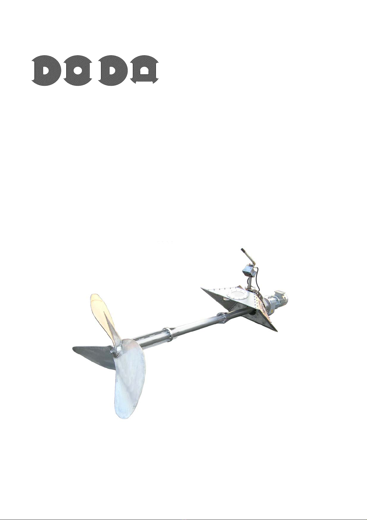
The machine is equipped with a hydraulic device for the mixing propeller tilt regulation.
The propeller turns clockwise.
With full tank, the rotation direction is recognizable only through the thrust effect
generated by the fluid present in the tank, which should move towards its middle.
The functioning of the mixer in the opposite direction to the recommended one could
cause strong vibrations, as well as serious damages to both the mixer and the tank.
On account of the different composition of the substrate to be mixed, it is necessary to adjust
the mixing propeller of immersion depth and to check that the propeller vanes are completely
covered by fluid during mixing.
During functioning no vortex or splashes have to be noticed in the fermenting medium.
The mixer has to work always in a enough full tank and with the propeller vane covered
at least 0,5m by the fluid; otherwise, a strong side vibration above all around the
Motor-Drive line unit will be noticed, which could damage the mixer.
Even during normal operating the mixer could swing sideways. Anyway, if the vibration does
not exceed 2 cm, that is not dangerous in consideration of the provided vibration-resistant
frame. Besides, this vibration can be prevented by increasing the revolutions per minute by
means of an inverter.
On the contrary, by too low rotation speed, strong side vibrations could occur,
therefore if necessary raise the revolutions per minute in order to avoid possible
damages to the mixer and the tank.
If, in spite of the compliance with the above-mentioned instructions, you do not obtain a
satisfactory mixing performance (e.g. because of a large tank diameter o a high content of dry
matter) , contact promptly the dealer or the manufacturer .
The dealer or the manufacture can not be considered responsible for damages due to incorrect
employment of the mixer.

8
If the tank is filled with already fermented substrate coming from other Biogas containers,
there could be material floating on the surface, due to a high dry matter content. That could
also occur in case of a fault in the Biogas plant and the consequent unforeseen mixer
stopping.
In case a great quantity of floating wastes is present, before starting the mixer, take
the necessary steps, which of course have to be previously agreed with the dealer or
the manufacturer of the machine.
Attention! The mixer drive line can be damaged by extreme side thrust caused by
excess floating materials.
The propeller vane can undergo excessive stress which could affect negatively the tank
stability.

9
5 TECHNICAL FEATURES
The data indicated refer to a standard supply.
The manufacturer reserves the right to introduce changes without prior notice.
1. All components touching the fluid , as well as all parts situated in the tank, are made of
stainless steel.
2. Mixer drive shaft in oil bath.
. Al Widia mechanical seal on the drive shaft
4. Control of the drive line lubrication oil level through a sight glass, set on the joining point
between the drive line and the gearbox.
5. Strong Bonfiglioli gearbox (Type C 80 2 con P180), 80 propeller rotation speed r.p.m. ,
with 1450 r.p.m. motor, at 50 Hz.
6. Self-cleaning three vane propeller, fixed on the shaft by means of a rotor hub.
7. Hydraulic regulation of the mixing depth through a hand pump and connection pipings,
standard supplied.
8. Roof or wall mounting frame.
5.1 Technical data
The data indicated refer to a standard supply.
The manufacturer reserves the right to introduce changes without prior notice.
Mixer type BG80 22kW BG80 18,5kW
Power /Motor type 22kW/4 poles 18,5kW/4 poles
Rated power 22 kW 18,5 kW
Rated voltage 400 V 400 V
Frequency 50 Hz 50 Hz
Revolutions per minute 1450 r.p.m. 1450 r.p.m.
Electric motor noise level 70dB 70dB
Voltage 4 Amp. 7 Amp.
Starting current cos ϕ 7 6,2
Power factor 0,85 0,84
Temperature probe PTC 160° PTC 160°
Substrate temperature 70° 70°
Gear ratio 18,1:1 18,1: 1
Propeller diameter 1600 mm 1500 mm
Drive line oil quantity 42 kg SAE80 – W90 42 kg SAE80 – W90
Gear box oil quantity 18 litres Shell Tivela
(or equivalent)
18 litres Shell Tivela
(or equivalent)
Hydraulic oil quantity for hand pump litres Nuto 68
(or equivalent)
litres Nuto 68
(or equivalent)
Total weight 960 kg 950 kg

10

11
6 INSTALLATION
6.1 Mounting instructions
The biogas mixer can be supplied with roof or wall mounting frame.
The different installation types have been specially designed to suit the different tank and
digester manufacturing features, as well as the different biogas plant locations and working
conditions.
To obtain an optimal mixing besides the suitable homogenization of the fermented substrate,
the technical design department or the dealer or the manufacturer have to check the correct
positioning of the mixer.
The location choice has to take into account that lift trucks have to access easily to that area.
Before installing the mixer, ask for the written authorisation of the person in charge
with the wall static calculations.
Doda is not responsible for possible tank damages caused by an unsuitable installation
or use of the mixer.
Explosion danger due to a thunderbolt!
Arrange for a lightning protection system.
Explosion danger due to the Absence of a ain equipotential bonding!
The grounding connection has to be executed only by a skilled electrician.
6.1.1 Mixer with roof ounting
To install the mixer, make a hole of 1 00 x 1 00 mm in the roof. Usually we recommend to
place the mixer at least 4-5 m far from the raw material input area, so that the propeller
radius of action could generate an uniform homogenization of the solid matters introduced.
The mixer position has to fit any other mixers already present.
The mixer thrust effect has not to be altered.
To ensure the correct mixer functioning, we recommend that it should be installed at least 1
meter far from the roof edge, so that the propeller can work also with fermented substrates
characterized by a high dry substance content.
During the design and the carrying out of the hole in the roof, remove the insulating
material (if present).

12
A resistant sealing between the mounting frame and the concrete surface is ensured
only if the surfaces surrounding the installation plate are polished and even.
Danger of explosion due to biogas e issions!
To ensure the mixer frame sealing, the tank cover has to be even enough, i.e. it has
not to have hollows or unevenness!
Check the correct grounding connection of the mixer!
6.1.2 Mixer with wall ounting
To install the mixer, make a hole of 1 00 x 1 00 mm in the wall.
It has to be installed at a such height, so that the distance between the upper corner of the
wall opening and the higher corner of the tank wall is 0,5m.
Usually we recommend to place the mixer at least 4-5m far from the raw material input area,
so that the propeller radius of action could generate an uniform homogenization of the solid
matters introduced.
The mixer position has to fit any other mixers already present.
The mixer thurst effect has not to be altered.
The standard provided mounting frame has a 0° tilt to the left, in order that the flow of the
mixed product turns in a clockwise direction.
Normally the vortex generated by the mixing vanes makes the rotary motion of the mixed
product easier.
During the design and the carrying out of the hole in the wall, take into account that
from the external side of the tank there has to be room enough for the manoeuvres
necessary for mixer installation and dismantling.
Furthermore take into account the suitable distance between other possible tanks or
equipments.
A resistant sealing between the mounting frame and the concrete surface is ensured
only if the surfaces surrounding the installation plate are polished and even.
Remove the insulating material situated on the tank outside side (if present).
In case of unevenness around the tank hole, remove it.
Remove or repair any tank wall defects, which could come out of its dismantling,
according to the laws in force concerning building.
An incorrect fixing of the mixer and the consequent vibrations due to mixing could both
damage the mixer and cause the leak of fermented substrate as well as environmental
damages.
Therefore, in case of doubts, we suggest that an expert should check possible faults to
be improved. All that carried out has to documented and attached with photos.

1
Danger of explosion due to biogas e issions!
To ensure the mixer frame sealing, the tank cover has to be even enough, i.e. it has
not to have hollows or unevenness!
Check the correct grounding connection of the mixer!
Near the mixer there have to be no trees, equipments or anything that could endanger
its correct functioning.
In case the mixer weight is excessive with regards to the tank wall bearing capacity,
the mounting frame can move away from the fixing systems.
The accidental leak of product from the tank can cause environmental damages.
The entry of any motor vehicle to the digester area without authorization is strictly
forbidden.
Danger of explosion due to biogas e issions!
To know at which distance the motor vehicles have to stay from the potentially
explosive atmospheres, consult the regional government safety rules in force
concerning biogas plants.

14
6.2 Mixer ounting and installation
6.2.1 General instructions
The electric motors installed on our mixers are suitable for an outside installation, therefore
humidity and dirt resistant, according to their IP55 protection degree.
Anyway, for a correct motor and gearbox operating, the outside temperature has not to be
lower than –10°C and higher than +40°C.
A correct motor ventilation has to ensured.
Prevent suction and discharge openings from blocking up and clogging due to rough dust.
Follow the safety rules of the local authorities concerning Biogas plants, as well as the
general safety provisions and the accident prevention regulations.
Hazard of injuries in case of not correctly fixed parts!
Instruction for ixer transport and installation
Attention! Transport the mixer only with suitable motor vehicles.
The loading and unloading of the machine can be carried out by means of:
- a lift truck (fig.1) or
- a hoisting crane (fig.2).
N.B.: the carrying capacity of the sling has to be seven times as much as the machine
total weight (if it is made of a textile fibre).
WARNING! Never lift the machine by catching on the weakest parts of the structure
(delivery pipes, etc...) or on moving parts, but use the lifting points foreseen on the
machine (fig. )!
Before lifting the machine, check if it is well-balanced.
Never move abruptly or bump the stainless steel parts with the forks of the lift truck.
Stopping under a hanging load during mixer lifting, transport or unloading, is strictly
forbidden!
Never leave any hanging load unattended!
Fig.1
Fig.2 Fig.3

15
Warning! Fla able and explosive at osphere!
No mounting or installing operations have to be carried out for any reason in potentially
explosive atmosphere!
The mixer can be installed and employed only in the allowed zones!
As concerns the position of the dangerous zones, refer to the Classification of the
potentially explosive zones which the user and the designer have to follow strictly!
Notify any change made in potentially explosive areas influenced by the mixer and
check if the new arrangement complies with the rules in force.
Hazard of injuries because of the fall of ixer co ponents!
Wear accident prevention shoes and safety helmet!
Hazard of injuries due to ixer co ponents with sharp edges!
Wear gloves!
Both during working and inspection phases, wear always proper clothing (overalls, gloves,
helmet, accident prevention shoes, fastened clothes, etc...).
If necessary use safety equipment (safety belt, sling, gas detector, oxygen mask, etc..)
In case mounting and installation in a potentially explosive atmospheres, before
starting, apply for the necessary authorization to the person in charge with it, who has
to provide you with the corresponding manuals and ask you to fill the necessary forms
in compliance with laws.
Employ the machine in a well-lit place.
Since the gases released by liquid manure are poisonous, check that:
- the work area is enough ventilated;
- the machine is not employed close to flames.
Never inspect the slurry pit alone!
If you loose your balance or if you feel faint due to fumes, ask for help immediately!

16
Only adults can use the machine and absolutely in a place not accessible to children.
Before any operation, check the stability of the whole working unit (machine and
tractor).
Do not carry out any repair, adjustment or maintenance operations if the unit is working
or supplied.
Cover the tank if you have not to work in it.
We recommend that the machine should be employed with all protections properly
positioned, according to the instructions mentioned in the previous paragraphs, in order
to avoid any contact with moving parts.
Do not damage or remove these protections.
During operating, maintenance or adjustment, the rubber parts of the machine (gaskets,
etc...) have not to come into contact with oil, grease or oil derivatives.
In case you do not use the machine for long time, keep it in a dry place and protected
against bad weather.
6.2.2 Mixer with roof ounting
Before mounting the mixer, check the dimensions of the hole made in the roof. Remove any
possible impurities present on the surface where you have to install it.
Check the flatness of the mounting and sealing surface and take the necessary improvements.
We recommend that you should use a suitable sealant between the mounting frame and the
foreseen installation surface.
To make the 12mm holes, use a drill plate. Before executing the first hole, line the plate with
the roof opening, so that the mixer could be correctly fixed with the anchor bolts.
In order not to move the drill plate, set the first fixing anchor bolt immediately after the first
hole has been made and press the plate firmly on the tank roof. Then you can go on with all
other holes.
To make the fixing operations easier, all other anchor bolts can be set after the mounting
frame installation.
In order to insert the anchor bolts easily and in the best way, clean the holes made
with compressed air and remove dust present on the hermetic surfaces.
Attention! Follow the installation instructions of the fixing anchor bolts!

17
Put anti-seize grease on the bolt threads, to prevent the anchor bolts from locking
before reaching the torque.
After having built the mixer into the roof, tighten the anchor bolts.
Check the bolt tightening after a few days.
6.2.3 Mixer with wall ounting
Before mounting the mixer, check the dimensions of the hole made in the wall, as well as the
correct mixer positioning.
Any changes have to be promptly agreed with the manufacturer absolutely before the
mounting.
Remove any possible impurities or insulating material present on the surface where you have
to install it.
Check the flatness of the mounting and sealing surface and take the necessary improvements.
We recommend that you should use a suitable sealant between the mounting frame and the
foreseen installation surface.
To make the 12mm holes, use a drill plate. Before fixing the drill plate, make a hole.
Attention! Follow the instruction for anchor bolt fixing.
After having fixed the first bolt, position the mounting frame on the tank wall by means of a
forklift truck.
Before making the left over holes, check again the exact positioning of the mixer.
For further mounting operations, follow the instructions given in paragraph 6.2. 1 General
instructions.

18
6.3 Electric connection
Our mixer is standard supplied without electric switchboard.
The motor starting has not to be direct but progressive (i.e. provided with soft starter,
inverter, etc..), so that the mixer reaches the nominal rotation speed in about -5 sec.
Avoid any sharp starting or stopping!
We reco end the use of an inverter!
Warning! Danger electricity!
The electric connection has to be carried out only by skilled workers and in a place
protected agains atmospheric precipitations, following the the directives in laws
concerning safety and accident prevention provisions.
Furthermore follow scrupulously the precise pertaining indications concerning electric
connections (i.e. cable section, safety rules, connection of a protection conductor, etc.).
Use only components in compliance with the regulations!
In potentially explosive atmospheres it is allowed to carry out electric connections only
if authorized!
Danger of explosion due to biogas e issions!
Check if the electric cables are correctly connected and protected!
The cable has to be long enough so that the mixer could tilt without problems!
Risk of crushing!
Do not place any electric cable near the hydraulic device and rotating parts!
Prevent the cable from:
- getting entangled!
- hanging down!
- being damaged!
- loosing or falling!
Protect the motor against excessive overheating by means of a suitable device: e.g.
circuit breaker with a phase failure protection.

19
The motor is equipped with thermistors, so that an additional thermal protection of the
machine could be used. (TMS / Thermal management system )
Attention! In case of an installation in compliance with ElexV regulations, employ only TMS trip
device (trip device for cold conductors).
The PTC thermistors/probes have a maximum measurement and testing equal to
2,5 V.
Install counters to set the functioning interval.
The supplied motors are protected against dust and water splashes, according to their
protection degree.
In case of ice or snow, take all necessary safety steps.
The motor supply line has to be carried out in conformity with the data indicated in the
connection box, situated on the motor lower part, and with those indicated on the
control panel.
6.3.1 Setting of the ixer operating interval
Hazard of da ages to the ixer and injuries to persons in case of
e ploy ent in the opposite rotation direction to that indicated!
The operating interval has to be programmed on the control panel of the Biogas plant!
The optimal operating period and pause depends on the manufacturing characteristics,
as well as on the working conditions and the fluid to be treated.
Only authorized workers have to program the control panel of the Biogas plant.
As indicative value, at the beginning the mixer can be programmed as follows:
- mixing time about 2-5 minutes and
- 20 minute pause.
In case of unsatisfactory mixing it is necessary to extend the operating time and
decrease the pause length.
A continous functioning is also allowed.

20
7 SETTING IN MOTION
7.1 Check at the first setting in otion
Check the motor rotation direction: the motor has to turn clockwise as indicated by the
arrow on the motor.
Start the motor for any seconds to check if the motor cooling fan turn rightwards.
The mixing propeller has to turn clockwise as well.
If the propeller is not clearly visible, it is necessary to check the rotation direction of the
mixing propeller of the activation motor.
Hazard of da ages to the ixer and injuries to persons in case of
e ploy ent in the opposite rotation direction to that indicated!
According to the electric polarization of the 400V connection, the motor rotation could
be wrong!
Check if the mixer is correctly fixed on the foreseen installation surface.
Check if all bolts set on the mixer are correctly fastened.
Both moving parts of the hydraulic direction adjusting device and the bearing bushes of
the fixing bolts have to be lubricated.
Set the unit in motion only after having checked the oil level in the drive line, in the gearbox
and in the hand pump for the hydraulic regulation.
The correct oil quantity is the following:
-18 litres of Shell Tivela oil (or equivalent) for the gearbox;
- 42 litres of SAE80 – W90 for the drive line;
- litres of Nuto 68 oil (or equivalent) for the hand pump.
In order to check oil, act as follows:
- unscrew inlet and vent caps;
- After having filled the machine up with oil, wait at least hours before setting the unit in
motion.
- Screw caps again.
- Check oil level periodically: it has never to be beyond the indicated level.
N.B. During filling up and check, the drive pipe, has to be as vertical as possible.
Other manuals for BG80 Series
1
This manual suits for next models
2
Table of contents
Other DODA Mixer manuals