Trigger input
»The trigger input makes it possible for the DFS6 A EV OCP HD to be tripped
remotely when a voltage of 12 to 24 V DC is applied. A charge controller could
»
a switch-on.
»
trip as a result of a residual over-current, the tripped output is active.
This is activated as soon as the toggle is no longer in the switched-on position.
»-
es quickly. If this output is not reset after an interruption to the power supply, the
DFS6 A EV OCP is faulty and must be replaced.
»
»Tip: Non-tripping due to a residual current is not detected.
If the operation indicators do not light up with the correct supply, the
DFS6 A EV OCP is faulty and must be replaced.
»Green:
Ready, over-current tripping 16 A
»
Ready, over-current tripping 32 A
»
Load current exceeded, a trip will follow
»
Fault, fault output is set
All professionally installed, unaltered devices are covered by warranty for the dura-
tion of the statutory warranty period from the day of purchase by the end user. The
warranty does not apply to damage incurred during transport or caused by short-
circuit, overloading or improper use. Should any defects in workmanship or mate-
rial be discovered within the warranty period, the company will provide repair or
replacement free of charge. The warranty will be rendered null and void if the device
is opened without authorisation.
electrical specialists. The installation of devices of this type is not ap-
propriate for electrical laypersons due to the considerable potential
dangers. These installation and operating instructions must be re-
tained, so that they can be referred to at a later stage. The operator of
the electrical installation must be informed about the application and
function of this protective device.
Devices with visible damage must not be installed or used.
Operation must only occur under normal ambient conditions free of corrosive
gases in order to preserve the correct tripping function in the long term. Corro-
sive gases are chlorine, ammonia and sulphurous air, for example. Residual cur-
The user must be made aware of regular function testing using the test key T.
The function test with the test key is not a substitute for regular testing of the
electrical system.
Erroneous tripping due to operational leakage currents or atmospher-
ic interference cannot be ruled out with absolute certainty. The conse-
quences must be considered and countermeasures taken where necessary.
Selective residual current circuit-breakers as well as surge protection measures
and system optimisations can provide a remedy.
If the residual current circuit-breaker cannot be switched on, or if the consumer
network is not connected, the device must be replaced.
Disposal is subject to the statutory regulations of the European Union (WEEE/
German Electrical and Electronic Equipment Act).
For further information and data sheets, please visit www.doepke.de/en/ and search
by the article number or scan the QR code on the front of the housing.
Intended use
DFS 6 A EV OCP series protective devices are residual current circuit-breakers with
integrated over-current protection. They provide protection through automatic
main use is to protect against DC residual currents greater than 6 mA DC as per IEC
62955. They meet the requirements for residual current protection in accordance
using a push-button which is also accessible to laypersons. Regular testing can also
increase the endurance of the circuit-breaker, as the mechanism of the latch is moved
when tripped in addition to the electrical test.
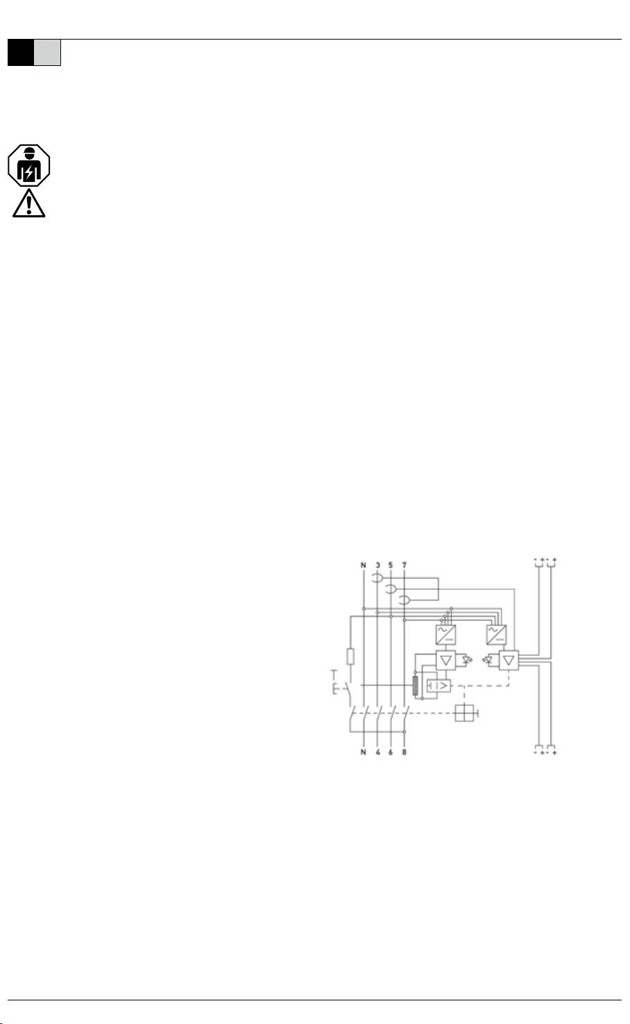
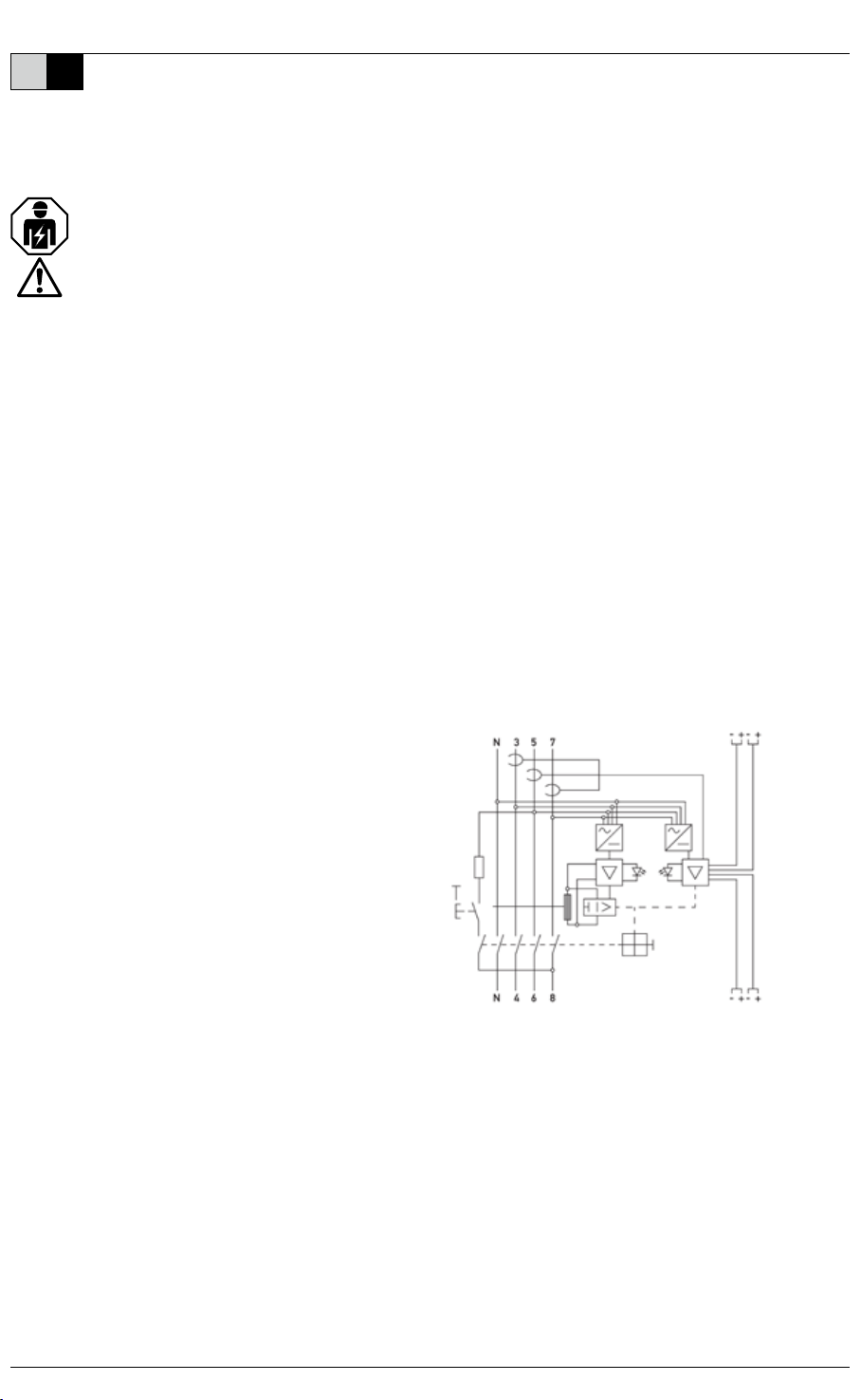
The electrical connection must be as shown in the wiring diagram and must comply
with the terminal designation on the device. The odd-numbered terminals are used
for the supply. The device must be installed on a mounting rail (TS 35) according to
DIN EN 60715 in distribution boards or charging devices that have to ensure protec-
tion against direct contact (which may be required depending on the location of use)
should always be provided for the operation of the DFS6 A EV OCP.
After the mains voltage is switched on, the LED for ‘DC detection operation’ should
light up green and the LED for ‘Over-current detection operation’ should light up
green or yellow (see ‘Operation indicator LED 2 over-current detection operation’).
A simple function test can be carried out with the assistance of test key T. When the
key is pressed, the DFS 6 A EV OCP must trip without noticeable delay. The toggle is
then in the middle position. Resetting to position ‘1’ is only possible if the toggle has
replaced immediately.
The ‘DC detection operation’ LED is referred to below as LED1 and the ‘Over-current
detection operation’ LED is referred to as LED2.
»The over-current release is based on characteristic C as per DIN EN 60898.
after various tripping times. The end of this time (min. 40 ms / max. 120 minutes)
»The over-current release can be switched from 16 A to 32 A. When a voltage of 12
to 24 V DC is applied to the 16 A/32 A terminals, it switches from 16 A to 32 A – LED
2 then lights up yellow. If no voltage is applied to the 16 A/32 A terminals and/or
no lines are connected to this input, the over-current release is set to 16 A – LED
2 then lights up green.
Doepke
||
DE EN