manuals.online logo
Brands
  1. Home
  2. •
  3. Brands
  4. •
  5. Doepke
  6. •
  7. Circuit Breaker
  8. •
  9. Doepke DRCCB 5 Series User manual

Doepke DRCCB 5 Series User manual

f+
ARD
N
L3
L2
L1
N
Lastseite / load-circuit
AUX
Vfour-pole, ARD (automatic reclosing device)
Testing and functional check (Selftest and Selftest restart)
After switching on the operating voltage (1) move the toggle to position I (2).
The automatic test cycle is activated as soon as the slider is moved left to posi-
tion AUTO ON, so that the toggle is completely covered (3). The green LED
illuminates (4).
Automatic operation is deactivated as soon as the slider is moved right to posi-

SET
SET
CLACK
3
LED EIN
LED ON
4
2
2
4
5
LED AUS
LED OFF
6
1EIN
ON
1EIN
ON
3
SET
SET
SET
SET
SET
SET
Selftest/Selftest Restart EIN/ONSelftest/Selftest Restart AUS/OFF
Manual functional check (Selftest and Selftest restart)
When the operating voltage (1) is on and once automatic operation (2) is deacti-
vated and test button T (3) is pressed, the device must trip (4).
SET
SET
CLACK
3
LED EIN
LED ON
4
2
2
4
5
LED AUS
LED OFF
6
1EIN
ON
1EIN
ON
3
SET
SET
SET
SET
SET
SET
Selftest/Selftest Restart EIN/ONSelftest/Selftest Restart AUS/OFF
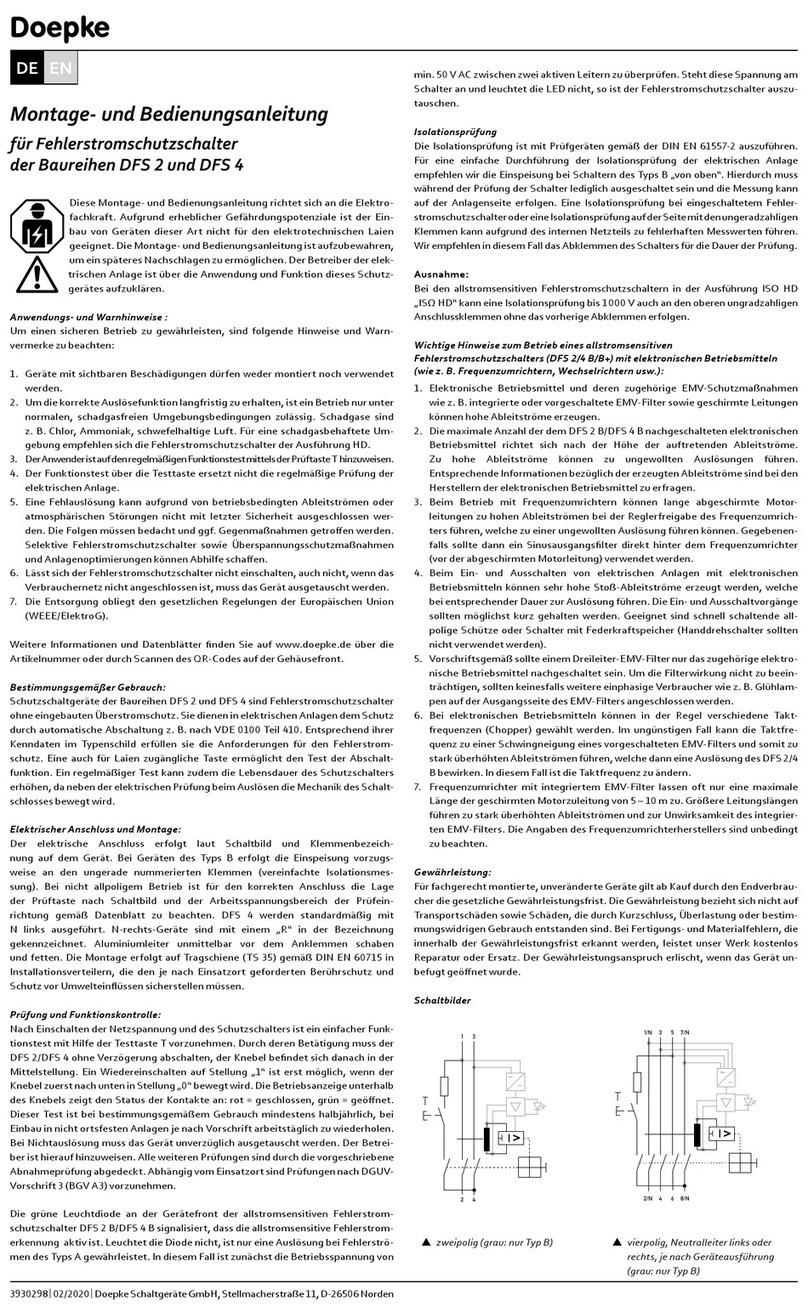
Installation and operating instructions
for two/four-pole residual current circuit
breakers DRCCB 5 ST and DRCCB 5 STR
-
ists. The installation of devices of this type is not appropriate for electrical lay-
persons due to the considerable potential dangers. The installation and operat-
ing instructions must be kept so that it can be referred to at a later stage. The
operator of the electrical system must be informed about the application and
function of this protective device.
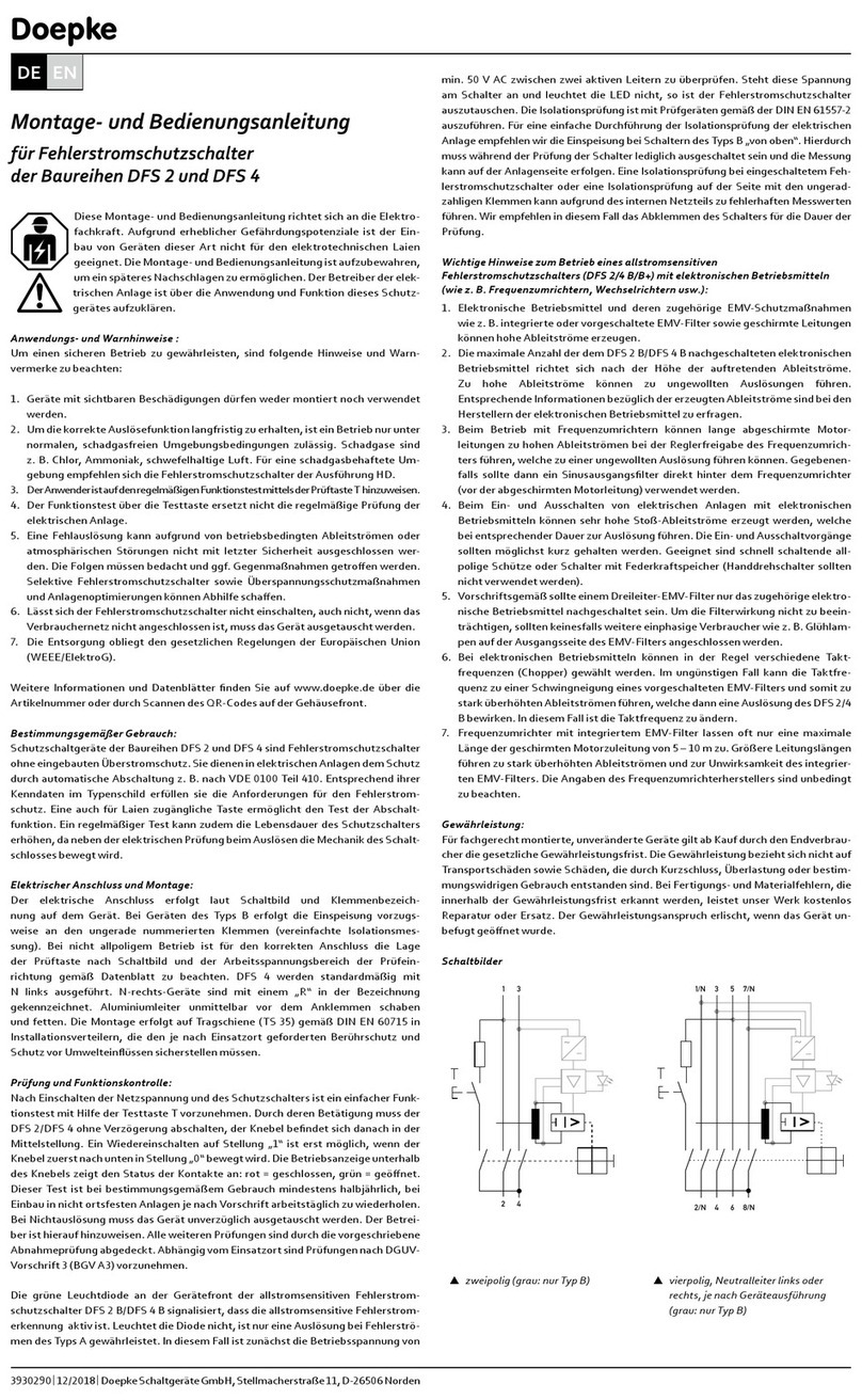
Application instructions and warnings
 Devices with visible damage must not be installed or used.
 Operation must only occur under normal ambient conditions free of corro-
sive gases in order to preserve the correct tripping function in the long term.
Corrosive gases include chlorine, ammonia and sulphur.
 Erroneous tripping due to operation related leakage currents or atmospher-
ic interference cannot be ruled out with absolute certainty.
           -
stream installation.
 According to standard DIN VDE 0100-530, automatic restart is only permit-
ted in areas where only trained electricians have access.
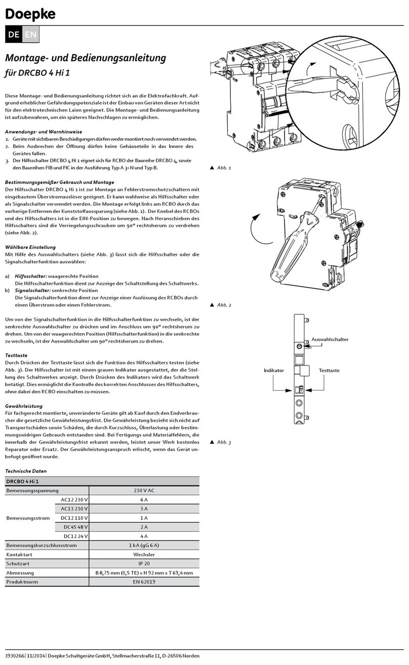
Intended use and installation
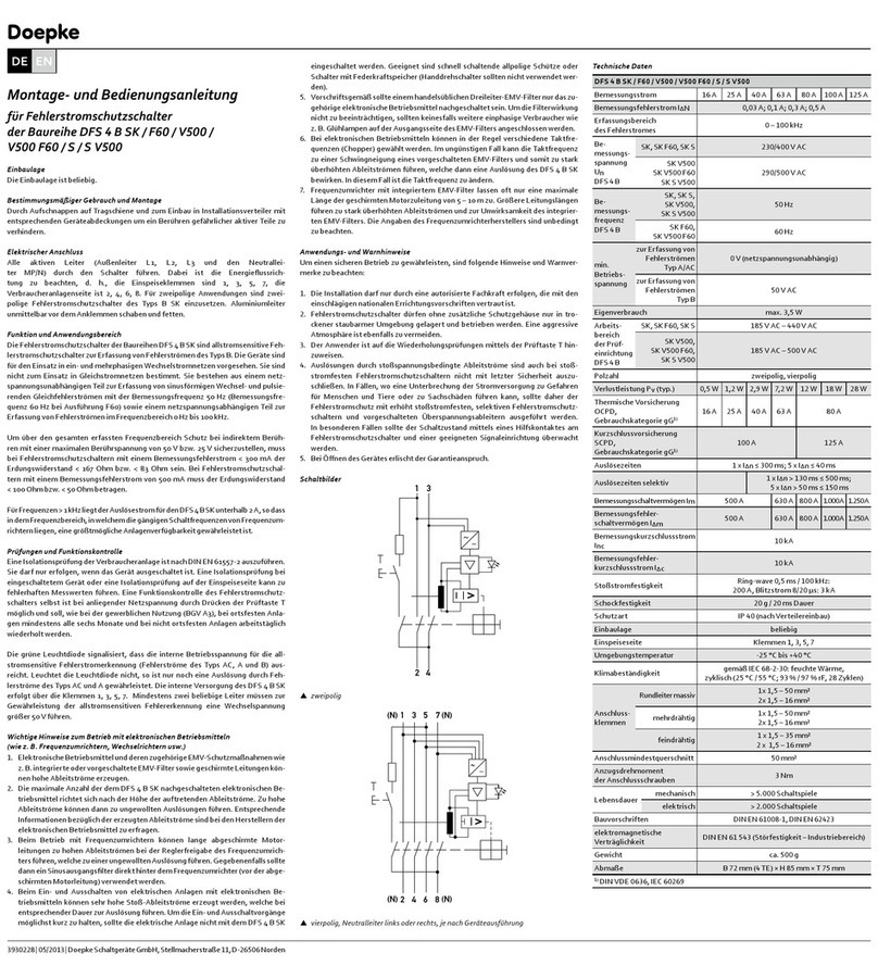
Series DRCCB 5 protective devices are type A pulsating AC-DC sensitive resid-
ual current circuit-breakers (RCCBs) which perform a monthly selftest without
interrupting the power supply. They are used to protect electrical systems by

DRCCB 5 ST (selftest): A monthly selftest is performed without interrupting
the power supply.
DRCCB 5 STR (selftest restart): A monthly selftest is performed without inter-
rupting the power supply. The insulation resistance is also measured every two
minutes after a trip (system check). If this resistance reaches a safe value, the
system is automatically restarted.
Installation notes
The device is snapped onto a mounting rail in accordance with EN 60715. The
connection must be made in accordance with the wiring diagram. Guide all ac-
tive conductors and the neutral conductor through the circuit breaker. Supply
must come from the top.
N
Tf+
ARD
N
L
Lastseite / load-cicuit
AUX
Vtwo-pole, ARD (automatic reclosing device)
SET
AUX
Doepke
|| 
DE EN
Mode 1: NO normally opened (make contact)




Press and hold the SET key for at least 5 s > then release

Press and hold the SET key for at least 5 s > then release

Press and hold the SET key for at least 5 s > then release

Pulse diagram for auxiliary contact
Note

(± 20%) every 3 hours (± 20%) in order to perform a check of the electronics.
Flow diagram for selftest/selftest restart
Function test of automatic reset (selftest
restart)
Once the operating voltage (1) is switched on
the device must be tripped manually by press-
ing the test button T (3). Press the button by
inserting a screwdriver into the corresponding
opening on the slider (5).
If the reset cycle is not performed correctly,
the insulation resistance of the system must
be checked.
Selftest and manual tripping
When the operating voltage (1) is on, the auto-
matic selftest for the residual current circuit-
breaker is performed monthly without inter-
rupting the system's power supply, as soon as
the slider is moved left to position AUTO ON
(2). The test can also be triggered manually
by pressing the SET key (3). The timer for the
monthly test is started when the operating
voltage (1) is on or when the SET key is pressed.
LED displays
SET
LED 1
rot/gelb
red/yellow
LED 2
grün
green
Auslösung Anlagen-
kontrolle Test
OK?
Wiedereinschaltung
Hilfskontakt
aktiviert Bereitschaft Anlagen-
kontrolle Test
OK?
LED 1 :rot LED 1 :rot
ja
nein
ja
LED 1 :rot
tripped system
control
re- closing
auxiliary contact
activated standby
LED 1 :red LED 1 :red
yes
no
yes
LED 1 :red
system
control
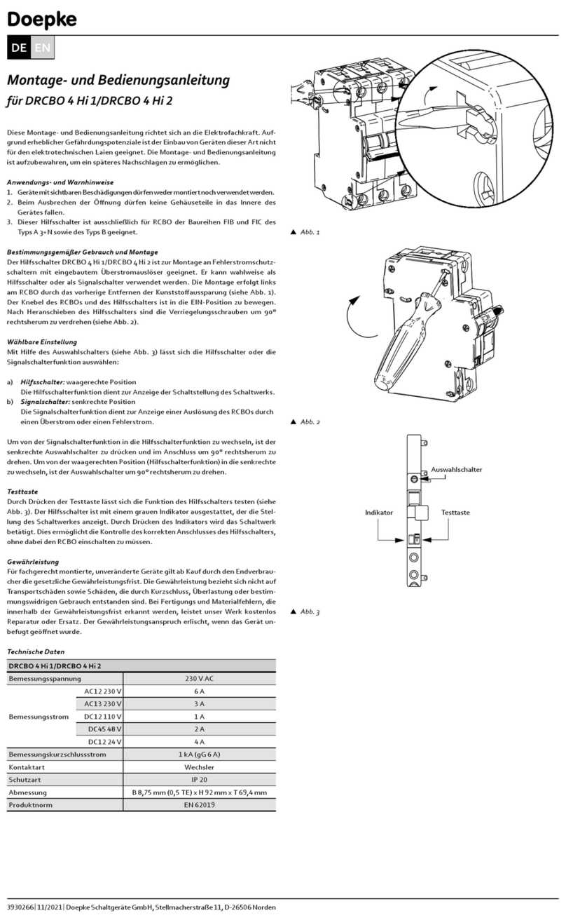
Conguring the auxiliary contact

moved left to position AUTO ON (I).
       
holding the SET key for at least 5 s. The switch be-


SET
EIN
ON
SET
SET
1EIN
ON
2
3
CLACK
SET
0,5 s 0,5 s 0,5 s0,5 s 0,5 s Selbsttest
ausgelöst
1 s
gelb
yellow
Selftest
5
6
7
rot
red
rot
red
rot
red
rot
red
0,5 s 0,5 s 0,5 s0,5 s 0,5 s Anlagenkontrolle/Selbsttest
5 s5s5s Wartemodus
blockiert
1 s
0,25 s
kein Fehlerstromschutz
0,15 s
gelb
yellow
gelb
yellow
rot
red
0,15 s
rot
red
rot
red
rot
red
rot
red
LED 1
1
2
3
4
rot
red
LED 1
LED 1
Selftest - Restart
0,25 s
0,15 s
gelb
yellow
rot
red
0,15 s
rot
red
LED 1
LED 1
LED 1
0,25 s
0,15 s 0,15 s 0,25 s
0,15 s 0,15 s
system control/Selftest
waiting mode
blocked
no residual current protection
Selftest
tripped
kein Fehlerstromschutz
no residual current protection
1
2
3
Fehler
Error
3 h (± 20 %)
Electronic - check
Fehler
Error
3 h (± 20 %)
NO
NC
NC +
Fehler
Error
500 ms (± 20 %) 3 h (± 20 %)
positive self - diagnosis
Elektroniktest
Electronic - check
Elektroniktest
Erfolgreicher Selbstest
100 ms (± 20 %)
500 ms (± 20 %)
500 ms (± 20 %)
230V~
2
LED ON
4
3
CLACK
5
1ON
SET
SET
SET
SET
Doepke
|| 
DE EN
LED ashing codes
Selftest/Selftest Restart o (slider moved right to position AUTO OFF)
LED 1 LED 2 Toggle
position Auxiliary contact
  Up On after

  Down 
Yellow  Up On Electronics fault
Yellow  Down On Electronics fault
  Up On ! No residual current
protection
  Down On ! No residual current
protection
Selftest Restart on (slider moved left to position AUTO ON):
LED 1 (red/
yellow)
LED 2
(green)
Toggle
position
Auxiliary
contact
 On Up 
On Down  System check
On Up  Selftest
On Down On Locked
Yellow On Up On Electronics fault
Yellow On Down On Electronics fault
On Up On ! No residual current
protection
On Down On ! No residual current
protection
On Down On Service mode
Selftest on (slider moved left to position AUTO ON):
LED 1
(red/yellow)
LED 2
(green)
Toggle
position
Auxiliary
contact
 On Up 
On Up  Selftest
On Down On Trip
Yellow On Up On Fault
Yellow On Down On Fault
On Up On ! No residual current
protection
LED 1
(red/yellow)
LED 2
(green)
Toggle
position
Auxiliary
contact
On Down On ! No residual current
protection
Selftest Restart:
 
 
 Locked = LED 1 continuously red
 

Selftest:
 
 Tripped = LED 1 continuously red
 

Functional overview
Selftest Selftest
restart
Automatic
selftest (uninterruptible power supply) 3 3
Display: selftest in progress 3 3
Display: selftest
 3 3
Automatic restart
when trip occurs 3
Insulation resistance measurement 3
Constant system check 3
Restart function lock in the event of a fault 3
Display: restart in progress 3
Display: fault 3
Automatic restart function can be toggled
 3
Auxiliary contact for remote signalling 3
Overcurrent protection PTC
Warranty
All professionally installed, unaltered devices are covered by warranty during
the statutory warranty period from the day of purchase by the end user. The
warranty is not applicable to damage incurred during transport or caused by
short-circuit, overloading or improper use. In the event of defects in workman-
ship or material being discovered within the warranty period, the company will
provide a repair or replacement free of charge. The warranty will be rendered
null and void if the device is opened without authorisation.
Dimensional drawings
106
90
17,8
6
44
73,5
7,4
45
Vtwo-pole
0,5 s 0,5 s 0,5 s0,5 s 0,5 s Selbsttest
ausgelöst
1 s
gelb
yellow
Selftest
5
6
7
rot
red
rot
red
rot
red
rot
red
0,5 s 0,5 s 0,5 s0,5 s 0,5 s Anlagenkontrolle/Selbsttest
5 s5s5s Wartemodus
blockiert
1 s
0,25 s
kein Fehlerstromschutz
0,15 s
gelb
yellow
gelb
yellow
rot
red
0,15 s
rot
red
rot
red
rot
red
rot
red
LED 1
1
2
3
4
rot
red
LED 1
LED 1
Selftest - Restart
0,25 s
0,15 s
gelb
yellow
rot
red
0,15 s
rot
red
LED 1
LED 1
LED 1
0,25 s
0,15 s 0,15 s 0,25 s
0,15 s 0,15 s
system control/Selftest
waiting mode
blocked
no residual current protection
Selftest
tripped
kein Fehlerstromschutz
no residual current protec
tion

106
124,8
17,8
644
73,5
7,4
45
Vfour-pole
Wiring diagram
1
N
2
N
Lastseite
load-circuit
1
N
3
5
2
N
4
6
Lastseite
load-circuit
Vtwo-pole
Technical data
Type Selftest/Selftest
Restart two-pole
Selftest/Selftest
Restart four-pole
Electrical properties
Standards Selftest: EN 61008-1,
VDE V 0664-120 (Annex M)
Selftest Restart:
EN 61008-1, EN 50557
Distribution System Selftest: TT-TN-IT
Selftest Restart: TT-TN
Rated operational voltage (Ue)  
Minimum operating voltage
(Ue min)

Maximum operating voltage
(Ue max)

Rated insulation voltage (Ui) 
Dielectric strength 
Rated impulse withstand
voltage (Uimp)

Rated frequency 
Residual making
and breaking capacity (IΔm)

Rated conditional residual short-
circuit current with fuse (IΔc)


Number of poles  
Type of residual current
operated protective device
A
Type Selftest/Selftest
Restart two-pole
Selftest/Selftest
Restart four-pole
short-time delayed Yes
Surge current strength |

Rated current (In) 
Rated residual
operating current (IΔn)
 
Resistance to earth
to block restart (Rdo)

Restart only)

Restart only)

Selftest Restart only)
Resistance to earth
to enable restart (Rd)

Restart only)
-
est Restart only)
-
est Restart only)
Current heat loss per current
path with In






Power consumption
during normal operation

Power consumption
during restart

Restart function Automatic (Selftest Restart only)
Supply From the top
Mechanical properties
Number of module widths  
Reclosing time 
Duration of selftest 
Maximum switching frequency 
Mechanical switching cycles
(number of restarts)

Maximum number of con-
secutive automatic reclosing
operations

Counter reset time number of
consecutive automatic reclos-
ing operations

Wiring , solid
Rated tightening torque 
Protection class 
Ambient temperature 
Resistance to climatic changes 
Auxiliary contact properties
Type of contact PhotoMOS
Operating voltage 
Maximum current 
Minimum current 
Operating frequency 
Utilisation category 
Type of contact 
contact with impulse
Wiring 
Rated tightening torque 
Key:
 230 V phase – neutral conductor
 In a system with no faults
 
 Contact switches for 100 ms (± 20%) after every successful selftest.
Vfour-pole
Doepke
|| 
DE EN

This manual suits for next models

2

Other Doepke Circuit Breaker manuals

Doepke DFS 6 A EV OCP Series Owner's manual

Doepke

Doepke DFS 6 A EV OCP Series Owner's manual

Doepke DRCBO 4 Hi 1 User manual

Doepke

Doepke DRCBO 4 Hi 1 User manual

Doepke DMCB 2 Series User manual

Doepke

Doepke DMCB 2 Series User manual

Doepke DFS 4 A EV User manual

Doepke

Doepke DFS 4 A EV User manual

Doepke DRCBO 4 Hi 2 User manual

Doepke

Doepke DRCBO 4 Hi 2 User manual

Doepke DFS 4 NA Series User manual

Doepke

Doepke DFS 4 NA Series User manual

Doepke DFS 4 Series User manual

Doepke

Doepke DFS 4 Series User manual

Doepke DFS 4 A EV User manual

Doepke

Doepke DFS 4 A EV User manual

Doepke DFS 4 Series User manual

Doepke

Doepke DFS 4 Series User manual

Doepke DFS2 025-2/0,03-B SK User manual

Doepke

Doepke DFS2 025-2/0,03-B SK User manual

Doepke DFS 2 User manual

Doepke

Doepke DFS 2 User manual

Doepke DFS 4 B SK Series User manual

Doepke

Doepke DFS 4 B SK Series User manual

Doepke DFS 4 B SK series User manual

Doepke

Doepke DFS 4 B SK series User manual

Doepke DFS F Audio Series User manual

Doepke

Doepke DFS F Audio Series User manual

Doepke DFS 2 AC User manual

Doepke

Doepke DFS 2 AC User manual

Doepke DFL 8 B SK Series User manual

Doepke

Doepke DFL 8 B SK Series User manual

Doepke DRCBO 2 Series Operation manual

Doepke

Doepke DRCBO 2 Series Operation manual

Popular Circuit Breaker manuals by other brands

Siemens 3RV1.2 operating instructions

Siemens

Siemens 3RV1.2 operating instructions

GenInterlock EAT-CH200A instructions

GenInterlock

GenInterlock EAT-CH200A instructions

TERASAKI TemBreak 2 instruction manual

TERASAKI

TERASAKI TemBreak 2 instruction manual

Siemens SENTRON 3WL10 manual

Siemens

Siemens SENTRON 3WL10 manual

Eaton Digitrip RMS Series Instructional Leaflet

Eaton

Eaton Digitrip RMS Series Instructional Leaflet

Eaton DILM185-S installation instructions

Eaton

Eaton DILM185-S installation instructions

LEGRAND Pass & Seymour 1594-CMA Installation and operating instructions

LEGRAND

LEGRAND Pass & Seymour 1594-CMA Installation and operating instructions

Siemens 3VA23 H Series operating instructions

Siemens

Siemens 3VA23 H Series operating instructions

ETI ETIBREAK NBS 160 Assembly instruction

ETI

ETI ETIBREAK NBS 160 Assembly instruction

Eaton AGM2-10-PKZ0 Instruction leaflet

Eaton

Eaton AGM2-10-PKZ0 Instruction leaflet

Allen-Bradley 140G Series manual

Allen-Bradley

Allen-Bradley 140G Series manual

Delixi Knight Series user manual

Delixi

Delixi Knight Series user manual

Siemens CNT3R Series operating instructions

Siemens

Siemens CNT3R Series operating instructions

NHP Terasaki TemBreak PRO P SE Series user manual

NHP

NHP Terasaki TemBreak PRO P SE Series user manual

Eaton C Series Instruction leaflet

Eaton

Eaton C Series Instruction leaflet

Delixi NAVIGATOR DZ47L Series user manual

Delixi

Delixi NAVIGATOR DZ47L Series user manual

OEZ OLFI Instructions for use

OEZ

OEZ OLFI Instructions for use

CHNT Power Smart Meter CPS1000 user manual

CHNT Power

CHNT Power Smart Meter CPS1000 user manual

manuals.online logo
manuals.online logoBrands
  • About & Mission
  • Contact us
  • Privacy Policy
  • Terms and Conditions

Copyright 2025 Manuals.Online. All Rights Reserved.