manuals.online logo
Brands
  1. Home
  2. •
  3. Brands
  4. •
  5. ABB
  6. •
  7. Circuit Breaker
  8. •
  9. ABB Record Plus FB100 User manual

ABB Record Plus FB100 User manual

Other ABB Circuit Breaker manuals

ABB Emax DC L3447 Quick guide

ABB

ABB Emax DC L3447 Quick guide

ABB SACE Emax Series Manual

ABB

ABB SACE Emax Series Manual

ABB SACE Emax 2 User manual

ABB

ABB SACE Emax 2 User manual

ABB SACE Tmax XT5 User manual

ABB

ABB SACE Tmax XT5 User manual

ABB HD4/R User manual

ABB

ABB HD4/R User manual

ABB SMISSLINETP FS401 Service manual

ABB

ABB SMISSLINETP FS401 Service manual

ABB R-MAG Series User manual

ABB

ABB R-MAG Series User manual

ABB MS 450 User manual

ABB

ABB MS 450 User manual

ABB SACE Tmax XT User manual

ABB

ABB SACE Tmax XT User manual

ABB VHK 20 Installation and operating instructions

ABB

ABB VHK 20 Installation and operating instructions

ABB SACE Emax 2 User manual

ABB

ABB SACE Emax 2 User manual

ABB SACE Emax E2.2 User guide

ABB

ABB SACE Emax E2.2 User guide

ABB SACE Emax User manual

ABB

ABB SACE Emax User manual

ABB SACE Emax E1 User manual

ABB

ABB SACE Emax E1 User manual

ABB TMAX MOE User manual

ABB

ABB TMAX MOE User manual

ABB AKD6-800A User manual

ABB

ABB AKD6-800A User manual

ABB HD4/ESB Series Quick guide

ABB

ABB HD4/ESB Series Quick guide

ABB VD4 36 Quick guide

ABB

ABB VD4 36 Quick guide

ABB GE Power Break II User manual

ABB

ABB GE Power Break II User manual

ABB H569-445 User manual

ABB

ABB H569-445 User manual

ABB VM1 User manual

ABB

ABB VM1 User manual

ABB SF6 LTB 245E1 BLG 1002A User manual

ABB

ABB SF6 LTB 245E1 BLG 1002A User manual

ABB OHB Installation and user guide

ABB

ABB OHB Installation and user guide

ABB F200 B Service manual

ABB

ABB F200 B Service manual

Popular Circuit Breaker manuals by other brands

Siemens 3VT9524-4TG30 quick start guide

Siemens

Siemens 3VT9524-4TG30 quick start guide

Acrel ASCB1 Series Installation and operation manual

Acrel

Acrel ASCB1 Series Installation and operation manual

Eaton NOVA LBS 15 Installation and operation instructions

Eaton

Eaton NOVA LBS 15 Installation and operation instructions

Siemens SIRIUS 3RV1742 Original operating instructions

Siemens

Siemens SIRIUS 3RV1742 Original operating instructions

WEG FHU ACW125 installation instructions

WEG

WEG FHU ACW125 installation instructions

TERASAKI NHP TemBreak PRO P160 Series installation instructions

TERASAKI

TERASAKI NHP TemBreak PRO P160 Series installation instructions

Siemens Sentron 3VA9157-0PK1 Series operating instructions

Siemens

Siemens Sentron 3VA9157-0PK1 Series operating instructions

hager TS 303 User instruction

hager

hager TS 303 User instruction

ETI EFI-4B Instructions for mounting

ETI

ETI EFI-4B Instructions for mounting

Gladiator GCB150 Installation instruction

Gladiator

Gladiator GCB150 Installation instruction

nader NDM3EU-225 operating instructions

nader

nader NDM3EU-225 operating instructions

Eaton 50DHP-VR Instruction handbook

Eaton

Eaton 50DHP-VR Instruction handbook

Gewiss 90 RCD Installation

Gewiss

Gewiss 90 RCD Installation

OEZ LFN Instructions for use

OEZ

OEZ LFN Instructions for use

Eaton Power Defense PDG2 Instruction leaflet

Eaton

Eaton Power Defense PDG2 Instruction leaflet

Bticino L4412CM2 quick start guide

Bticino

Bticino L4412CM2 quick start guide

OEZ 3VA9-RS-4VBH1 Installation, service and maintenance instructions

OEZ

OEZ 3VA9-RS-4VBH1 Installation, service and maintenance instructions

Siemens PSR Instructions, Installation, Operation, Maintenance

Siemens

Siemens PSR Instructions, Installation, Operation, Maintenance

manuals.online logo
manuals.online logoBrands
  • About & Mission
  • Contact us
  • Privacy Policy
  • Terms and Conditions

Copyright 2025 Manuals.Online. All Rights Reserved.

Record PlusTM FB100 1 Pole, 2 Pole & 3
Pole
Caution: This product is NOT suitable for use in
equipment not specifically designed to accept it .
Contact equipment manufacturer for possible
equipment modifications.
Important: Cet appareil nedoit pas etre employe
dans un equipement non specialement adapte a
cet effet. Contactez le constructeur concernant les
possibles modifications a apporter a l'equipemen.
Congratulations and thank you for choosing
the Record PlusTMfamily of current limiting
circuit breakers.
Record PlusTM circuit breakers are designed
to provide overload and short circuit
protection to electrical distribution and
utilization equipment.
All units use integrated modular circuit
breaker technology to allow flexibility in a
broad range of applications.
All Record PlusTM circuit breakers are listed by
Underwriters Laboratories to UL489 stand-
ard and by the CSA Standard C22.2, No. 5.
Record PlusTM circuit breakers are designed
and manufactured to exceed our global
customers’ high standards for performance,
reliability and quality.
Warning: DANGER of Electrical shock or injury.
Ensure ALL electrical power supplies are "OFF”
before installing or removing any devices. The
breaker, trip unit or accessories, MUST ONLY be
installed and serviced by QUALIFIED personnel, see
NEMA publication Ab4.
Avertissement: Danger contre les risques
d'électrocutions. S'assurer avant TOUTES
manipulations du disjoncteur que les différentes
sources d'alimentation sont en position «OFF». Les
disjoncteurs, unités de protection
ou accessoires doivent être installés par des
personnes qualifiées et habilitées. Lira NEMA publ
ication AB4.
1
DEH41073 INSTALLATION INSTRUCTIONS
Record PlusTM FB100 Molded Case Circuit Breaker
A. Unpack and inspect
Unpack the breaker or switch and inspect it for any
shipping damage. Insure the breaker has the proper
ampere, voltage and interrupting ratings for the
application. Also check breaker operation, see
Section D. Install any accessories (Section H) and
terminal lugs (Section C) using supplied installation
instructions. Check all accessories for proper
voltage ratings, installation, wiring routing and
operation. Attach appropriate labels to side of the
breaker if internal accessories have been installed,
see Figure 5.
B. Installation
Using figs. 1.a, 1.b and 1.c drill and tap all mounting
holes and make any necessary front panel
escutcheon cut outs. Using the breaker hardware kit,
which includes four screws and lock washers, mount
the breaker. Mounting kits:
SEMSK1 #10-32 x 2-7/8in
Torque mounting screw to 20 lb-in.
For breaker orientation see Figure 2.
Dimension for drill pattern & escutcheon Fig. 1.a (3 pole)
A 127.3mm 5.00 in F 25.0mm 0.98 in
B 98.1mm 3.86 in G 15.0mm 0.59 in
C 15.0mm 0.59 in H 70.0mm 2.76 in
D 129.7mm 5.11 in J 10.0mm 0.39 in
E 34.9mm 1.38 in K 25.4mm 1.00 in
Dimension for drill pattern & escutcheon Fig. 1.b (2 pole)
A 127.3mm 5.00 in F 25.0mm 0.98 in
B 98.1mm 3.86 in G 15.0mm 0.59 in
C 15.0mm 0.59 in H 70.0mm 2.76 in
D 129.7mm 5.11 in J 10.0mm 0.39 in
E 17.5mm 0.69 in K 25.4mm 1.00 in
Dimension for drill pattern & escutcheon Fig. 1.c (1 pole)
A 127.3mm 5.00 in F 5.1mm 0.20 in
B 98.1mm 3.86 in G 15.0mm 0.59 in
C 15.0mm 0.59 in H 70.0mm 2.76 in
D 129.7mm 5.11 in J 10.0mm 0.39 in
E 34.9mm 1.38 in K 25.4mm 1.00 in
C. Wire Terminal Connections
Note: When using aluminum wire, use a joint
compound recommended by the wire manufacturer.
Important: Dans les cas d'emploi de cable
aluminum, utilizez le lubricant recommende by par
le fabricant.
Check to make sure all terminals are torqued to the
proper value. (8.84 lb-in = 1 Nm)
15 - 20A Saddle clamp kit FCALK12
Cu/Al wire, strip length- 0.40 - 0.45 in (10 – 11mm)
#14 -10 AWG Torque to 35 lb-in (4Nm)
30 - 60A Lug kit FCALK13 (FCOLK13 CU lug
body)
Cu/Al wire, strip length- 0.40 - 0.45 in
(10 – 11mm)
#10 AWG
#8 AWG
#6, & 4 AWG
Torque to 35 lb-in (4Nm)
Torque to 40 lb-in (4.5Nm)
Torque to 45 lb-in (5Nm)
70 -100A Lug Kit FCALK14 (FCOLK14 CU lug
body )
Cu/Al wire, strip length- 0.40 - 0.45 in (10 –
11mm)
#4 AWG Torque to 45 lb-in (5NM)
# 3 - #1/0 AWG Torque to 50 lb-in (5.7Nm)
—
Fig 1.b
—
Fi g 1.c
—
Fig 1.a
Mounting holes and escutcheon (hatched area) details
Note: Opening C by G is only required for access to
Push-to-trip button
ONI
II
O
OO
OFF
OFF
DOWN
UP
90°
90°
90°
90°
90°
90°
90°
90°
2
—
Fig 2. Circuit breaker orientation
ON
UP
DOWN
D. Circuit breaker operation
The breaker contact status is indicated by the handle
position, and the positions are marked on either side
of the handle escutcheon, clearly showing the status of
the breaker contacts. ON and/or I indicate breaker is
ON and OFF
and/or O indicate breaker is OFF.
The breaker tripped position
is indicated by the symbol
To close the breaker from the OFF position move the
handle to the ON position. To close the breaker from
the trip position, first move the handle fully to the
OFF (reset) position then to the ON position. See
Figure 4. A Push-To-Trip button is provided for
convenience of testing the mechanical trip operation
of the breaker, see Figure 3. The Push-To-Trip should
be tested annually.
ON
II
OO
TRIPPED
OFF
3
—
Fig 3. Circuit Breaker Push-To-trip
—
Fig 4. Mechanical Operation of the Circuit Breaker
—
Fig 5. Terminate wire as shown (For FBL type
circuit breakers)
Fig 3. Note
Push to trip operation is same on all the three versions of the breaker (1pole, 2pole & 3 pole)
L'action "Pousser pour declencher" est identique pour les trois versions de disjoncteurs (1pole, 2poles,
3poles)
Fig 4. Note
Mechanical operation is same on all the three versions of the breaker (1pole, 2 pole & 3 pole)
L'action mecanique "ouvrir / fermer" est identique pour les trois versions de disjoncteurs (1pole, 2 poles,
3poles)
Fig 5. Note
Terminate wire - FBL type
Raccordement des conducteurs pour le type FBL.
E. Troubleshooting
Ensure that breaker is installed correctly and all
terminal connections are torqued per instructions.
If the breaker fails to close check:
1.
2.
3.
4.
5.
For overload and short circuit on the system.
Handle position - TRIPPED - reset by moving
handle fully to OFF position and then to the ON
position, see Figure 4.
Undervoltage trip is supplied with rated
voltage.
Shunt trip is de-energized and no trip signal
exists
Breaker trip unit settings are properly adjusted.
Installation instruction
references:DEH40324 –
Auxiliary switch & bell alarms.
DEH40363 – Undervoltage
release & shunt trip modules
DEH40532 – Terminal lugs.
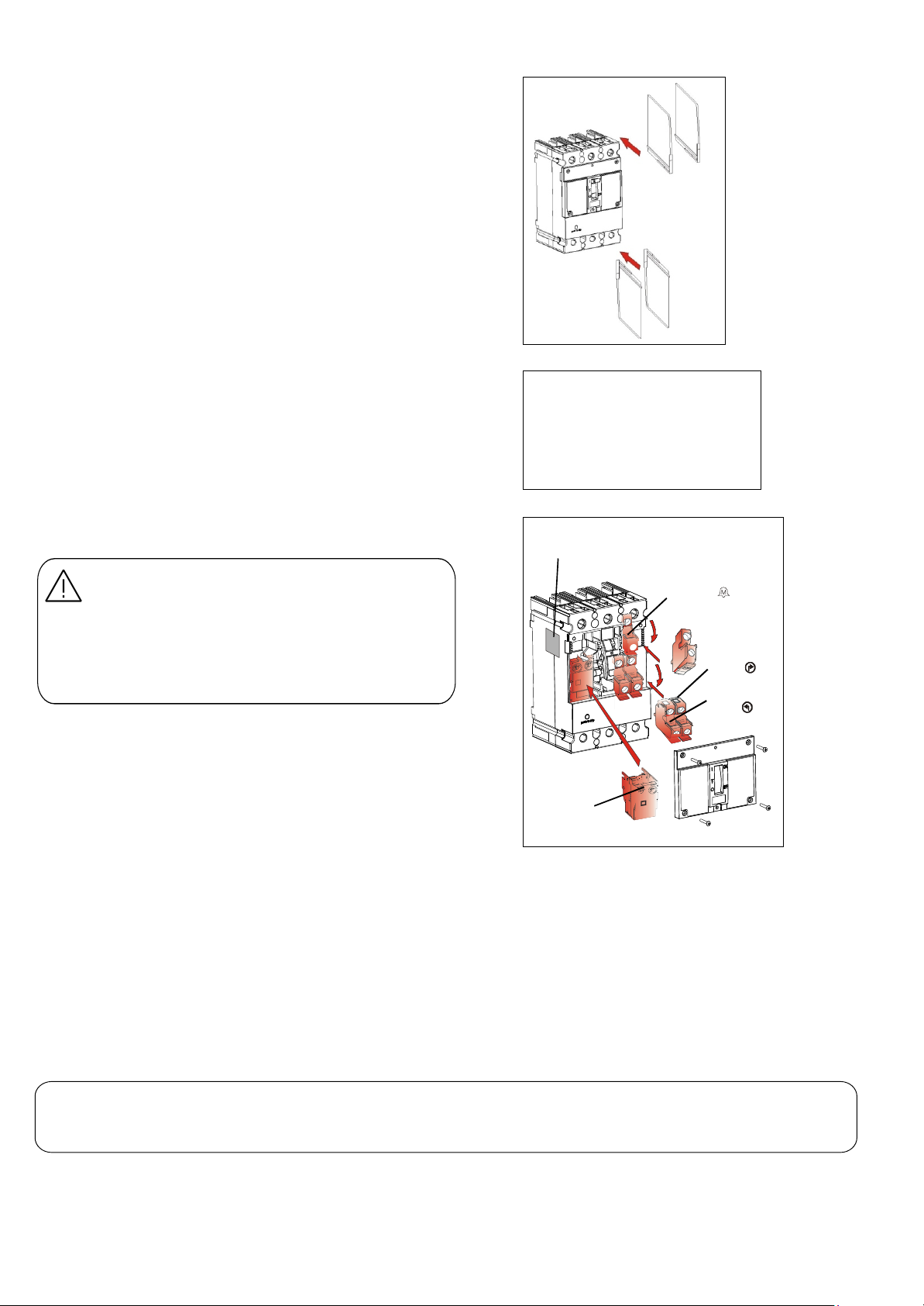
Optional inter-
phase Barriers
Applied accessorylabel to
side of breaker
Bell al arm swit ch ID
Outside auxiliary
switch ID
Inside auxili ary
switch ID
Shunt trip and
Unde rvoltage modu le
Warning: Danger of electrical shock or injury. Turn off
power supplies ahead of equipment before attempting
to service.
Important:: Danger d’electrocution. Couper
l’alimenation avant d’effectuer toute action d’entretien.
Operate the breaker push to test button and toggle the
handle several times, testing the mechanical operation
of the device. If there are any signs of damage or if the
mechanism is sluggish or sticky, replace the breaker.
For abnormal or heavy duty conditions refer to NEMA
publication AB4 and for recommended maintenance
practices NFPA70B.
G. Storage
Store in a dry, dust free, environment protected from
corrosion. Long term storage should be in the original
shipping carton. Temperature range –40°C to +80°C.
H. Accessories
For full details of the accessories and their application,
contact your local ABB representatives. When installing
accessories read the accompanying accessory
installation instruction and follow carefully all cautions
and warnings.
®
—
Fig 6. Typical Accessories. See Buylog for Details
4
1SQC930037M0201, DEH41073 February 2020
—
ABB Inc.
305 Gregson Drive
Cary, NC 27511.
electrification.us.abb.com
—
We reserve the right to make technical
changes or modify the contents of this
document without prior notice. With
regard to purchase orders, the agreed
particulars shall prevail. ABB Inc. does not
accept any responsibility whatsoever for
potential errors or possible lack of
information in this document.
We reserve all rights in this document and
in the subject matter and illustrations
contained therein. Any reproduction or
utilization of its contents – in whole or in
parts – is forbidden without prior written
consent of ABB Inc.
Copyright© 2019 ABB
All rights reserved
—
GE is a trademark of GE. Manufactured
by ABB Inc. under license from GE.
If technical assistance is required contact your
local ABB sales office. In the US call ABB Post
Sales Customer Service, 1-888-437-3765.
F. Maintenance
Generally no maintenance is required but it is
recommended that the breaker be cleaned and
inspected on an annual basis.
Note: For a 2 pole breaker there are no auxiliary
switch & bell alarm switch; For a 1 pole there are no
accessories; Installation of an accessory in a 2 pole
breaker is the same as a 3 pole breaker.
These instructions do not cover all details or variations in equipment nor do they provide for every possible contingency that may be met
in connection with installation, operation, or maintenance. Should further information be desired or should particular problems arise that
are not covered sufficiently for the purchaser’s purposes, the matter should be referred to the ABB Company. The breaker is a sealed unit,
which contains no user serviceable parts, tampering with seal will void warranty.