311.01.21 en / 335A
Phase / motor
voltage L1/L2/L3: 3 AC 200 V -10 % ... 480 V + 10 %
Nominal frequency: 50 / 60 Hz
Nominal motor power PN
at 400 V: 11 kW
Switching frequency
at 3 x IN, 5 s, ϑU= 45°C: 20 / h
max. permissable braking current: 50 A eff.
Min. motor power: 0.1 PN
Start torque: 20 ... 80 %
Ramp time: 1 ... 20 s
Braking time: Max. 20 s
Braking delay: 750 ms
Braking voltage: DC 10 ... 90 V
Start delay: 250 ms
Auxiliary voltage UH
model DC 24 V: A1/A2, DC 24 V, + 10 %, - 15 %
Power consumption: 2 W
Residual ripple max.: 5 %
Max. semiconductor fuse: 6600 A2 s
Inputs
Control input X1, X2: DC 24 V / 2.5 mA / edge triggered
Input P2 / P3 for bi-metal contact
Switching current: DC 1 mA
Switch voltage: DC 5 V
Input P1 / P2 for PTC-sensor
Thermal sensor: According to DIN 44081
Number of sensors: 1 ... 6 in series
Response value: 3 kΩ
Measuring voltage: Max. DC 5V
Monitoring Output
Contacts: 3 x 1 NO contacts
Thermal continous current Ith:4 A
Switching capacity
to AC 15
NO contact: 3 A / 230 V IEC/EN 60947-5-1
Electrical life:
to AC 15 at 3 A,
AC 230 V: 2 x 10⁵switch. cycl. IEC/EN 60947-5-1
Short circuit strength
max. fuse rating: 4 A gG / gL IEC/EN 60947-5-1
General Data
Temperature range
Operation: 0 ... + 45 °C
Storage: - 25 ... + 75 °C
Altitude: < 2000 m
Clearance and creepage
distances
Rated impulse voltage /
pollution degree
Control voltage to auxiliary
voltage, motor voltage: 4 kV / 2 IEC 60664-1
Auxiliary voltage to
motor voltage: 4 kV / 2 IEC 60664-1
motor voltage to heat sink: 6 kV / 2 IEC 60664-1
EMC
Electrostatic discharge: 8 kV (air) IEC/EN 61000-4-2
HF-irradiation
80 MHz ... 1 GHz: 10 V / m IEC/EN 61000-4-3
1 GHz ... 2,5 GHz: 3 V / m IEC/EN 61000-4-3
2,5 GHz ... 6 GHz: 1 V / m IEC/EN 61000-4-3
Fast transients: 2 kV IEC/EN 61000-4-4
Surge voltages
between
wire for power supply: 1 kV IEC/EN 61000-4-5
between wire and ground: 2 kV IEC/EN 61000-4-5
HF wire guided: 10 V IEC/EN 61000-4-6
BL 9028.03 3 AC 200 ... 480 V 50/60 Hz UHDC 24 V 11 kW
Article number: 0068352
•Nominal motor power
at 3 AC 400 V: 11 kW
•Control input X1, X2: DC 24 V
•Width: 112.5 mm
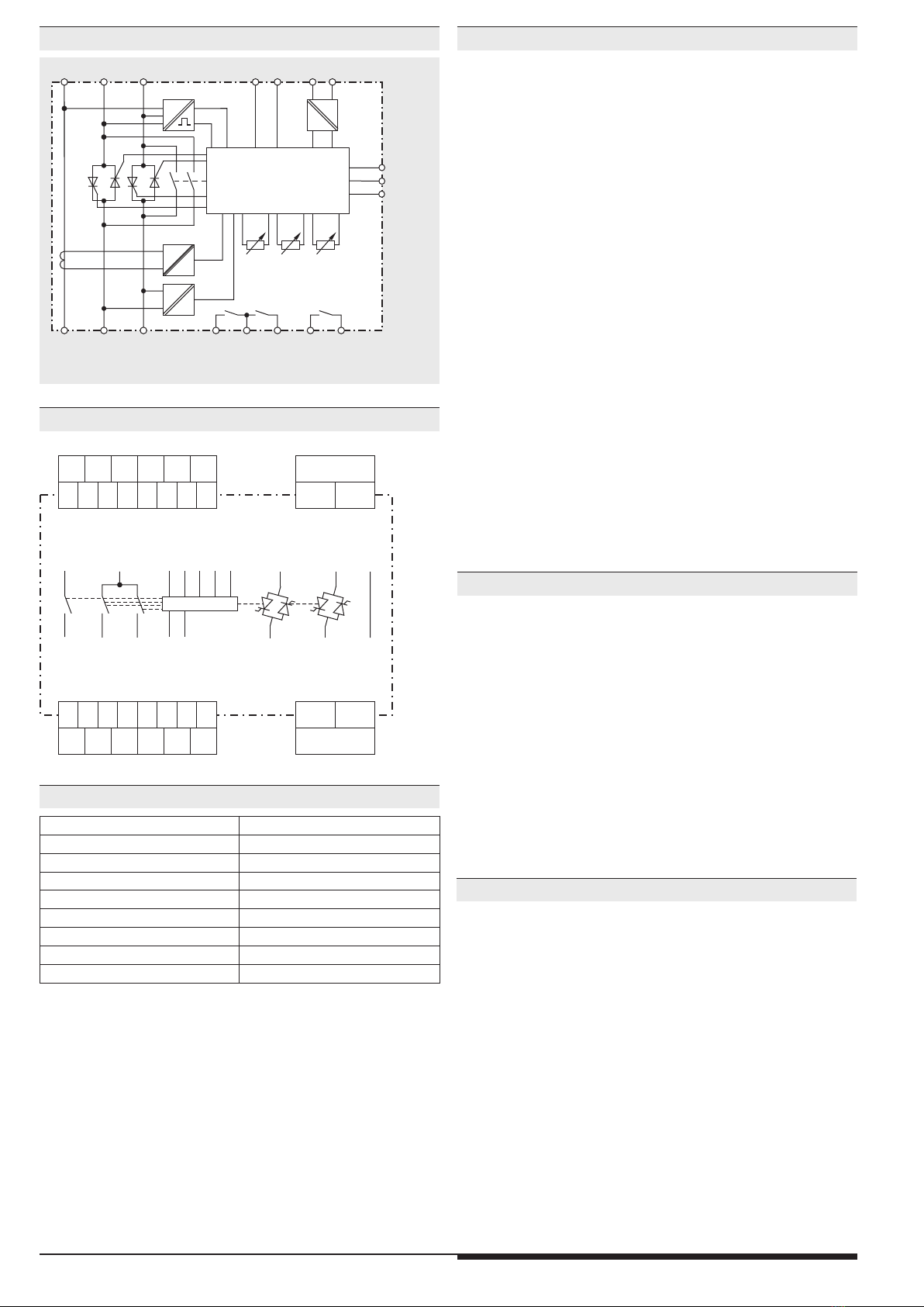
Technical Data Technical Data
Standard Type
Interference emission
Wire guided: Limit value class A IEC/EN 60947-4-2
Radio irradiation: Limit value class A IEC/EN 60947-4-2
The device is designed for the usage
under industrial conditions (Class A,
EN 55011). When connected to a
low voltage public system (Class B,
EN 55011) radio interference can be
generated. To avoid this, appropriate
measures have to be taken.
Degree of protection:
Housing: IP 40 IEC/EN 60529
Terminals: IP 20 IEC/EN 60529
Vibration resistance IEC/EN 60068-2-6
Frequency range: 10 ... 100 Hz
Amplitude: 0.35mm peak to peak up to 54 Hz
Acceleration: Above 54 Hz constant acceleration 4 g
Climate resistance: 0 / 045 / 04 IEC/EN 60068-1
Wire connection
Load terminals: 1 x 10 mm2solid
1 x 6 mm2stranded ferruled
Control terminals: 1 x 4 mm2solid or
1 x 2.5 mm2stranded ferruled (isolated) or
2 x 1.5 mm2stranded ferruled (isolated)
DIN 46228-1/-2/-3/-4 or
2 x 2.5 mm2stranded ferruled
DIN 46228-1/-2/-3
Stripping length: 10 mm
Wire fixing
Load terminals: Plus-minus terminal screws M4
box terminals with wire protection
Fixing torque: 1.2 Nm
Control terminals: Plus-minus terminal screws M3.5
box terminals with wire protection
Fixing torque: 0.8 Nm
Mounting: DIN rail mounting IEC/EN 60715
Weight: 1135 g
Dimensions
Width x height x depth: 112.5 x 85 x 121 mm
BL 9028. 03/_ _ _ 3 AC 200...480 V 50/60 Hz UHDC 24 V 11 kW
Nom. motor power
at 3 AC 400 V
Aux./Control voltage
Nom. frequency
Phase / motor voltage
Variant
0 = Standard
0 = Standard
1 = Input P1/P2/P3
for motor temp.
monitoring
0 = With standstill
detection
Contacts
Type
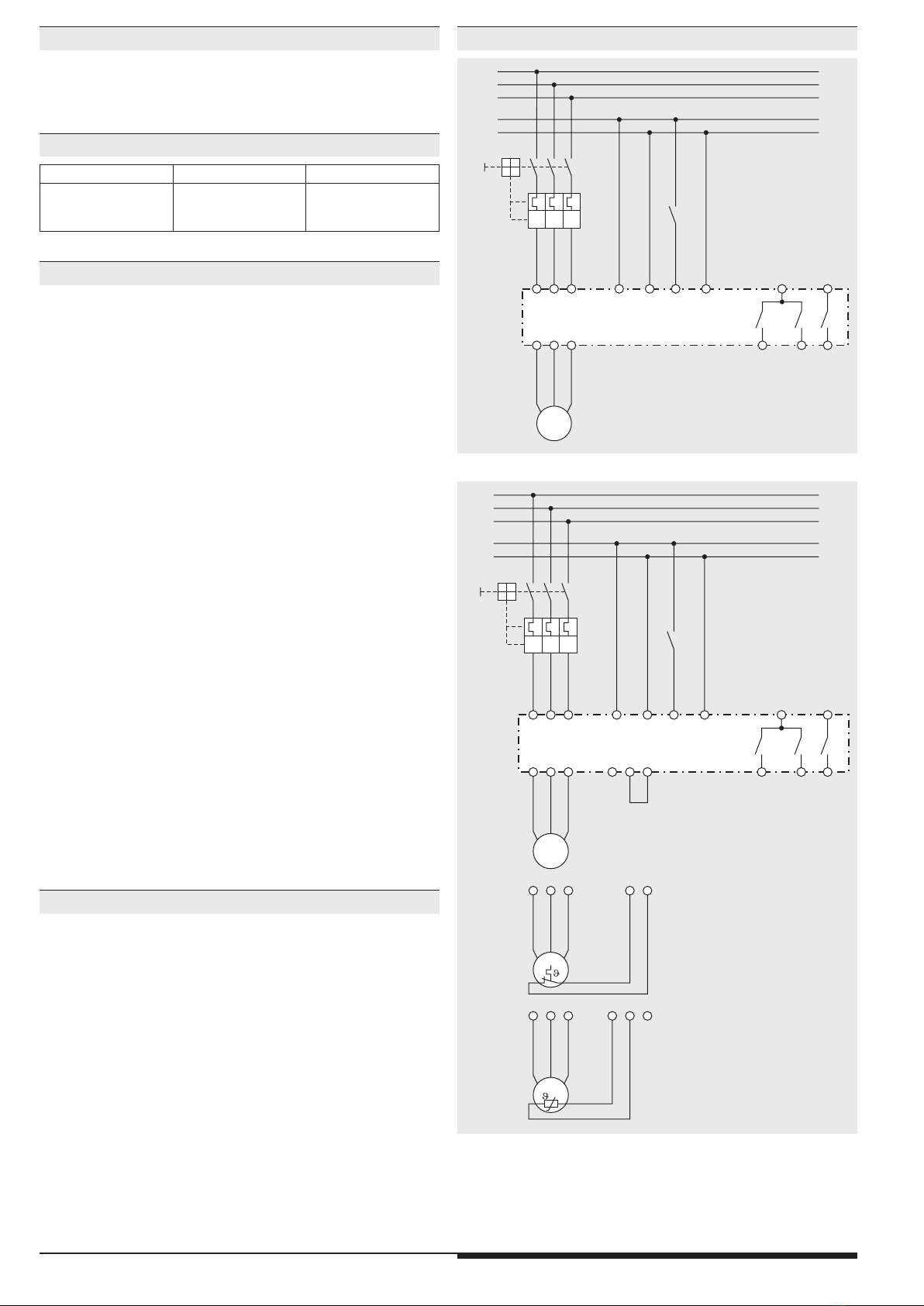
Ordering Example
Variant
BL 9028.03/_1_: Motor protection with bi-metal contact or
PTC thermal sensor