207.07.23 en / 755A
ThedeviceissuppliedwithDCauxiliaryvoltageviaterminalsA1(+)/A2.
Switchingontheauxiliaryvoltage(Power-On)isfollowedbyaninternal
self-testfor12s(see„Devicetestfunctions“).Thetestprocessisvisible
withthestatusLED.Afterthis,measurementoftheinsulationresistance
inthemeasuringcircuitsbeginsandthestatusLEDchangesintogreen.
Measuring circuit
(Insulation measurement between terminals L(+) / L(-) and PE1/PE2)
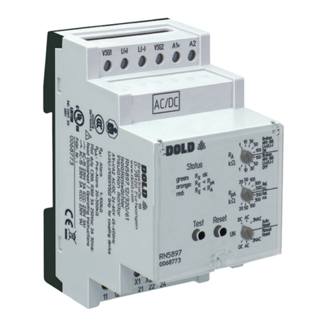
TheinsulationmonitorRN5897/240canbeusedbothwithballast(VSG)
andwithoutVSG.Max.mainsvoltageandconnectiondiagramshaveto
beobserved!
Iftheinsulationmonitorisoperatedwithoutcouplingdevicetheterminals
L(+)and L(-)havetobeconnecteddirectlytothe voltage systemtobe
monitored.andtheterminalsVSG1/L(+)andVSG2/L(-)eachhavetobe
bridged(seealsooperationwithcouplingdevice).
Abrokenwiredetectionthatcanbedisabledprovidesafaultsignalifboth
terminalsL(+)andL(-)arenotlinkedbytheconnectednetwork.
Thetypeofthevoltagesystemortheconnectionmethod(AC,DC,3NAC)
hastobecorrectlyadjustedontherotationalswitch"UN".
AlsotheterminalsPE1andPE2havetobeconnectedwith2separate
wirestotheprotectiveearth.Aninterruptionofawirealsocausesafault
signal(seesection”Behavioronfaultyconnection”).Themonitoringof
thePEconnectioncannotbede-activated.
Tomeasuretheinsulationresistanceanactivemeasuringvoltagewith
changingpolarityisconnectedbetweenL(+)andL(-)andPE1/PE2.
Attheendofameasuringcycletheactualinsulationresistanceisproduced
andindicated.TherelayforalarmK1switchwhendroppingunderthe
adjustedresponsevalue.InadditionthestatusLEDlightsupredonalarm.
Manual reset of fault message
Withthe2-sectionrotationalswitc h" UN",manualorautoresetofthealarm
canbeselected.Ifmanualresetisactivatedtheinsulationfaultsignalof
t h e m e a s u r i n g c i r c u i t i s s t o r e d w h e n d r o p p i n g u n d e r t h e a d j u s t e d r e s p o n s e
valuealsoiftheinsulationresistancegoesbacktohealthystate.Pressing
the„Reset“buttononthefrontsidefor2s,thealarmsignalisresetifthe
actualinsulationresistanceisinhealthystate.
Indicator relay for insulation fault and device failure
The function of the relays K1 (contacts 11-12-14 for alarm) and K2
(contacts21-22-24)canbealteredbetweenenergisedontrip(relayn.o.)
orde-energizedon trip(relayn.c.). Whenenergised on triptherelays
energizewhenthevaluedropsbelowthesettingoratdecivefailure,when
de-energisedontrip,therelaysde-energizewhenthevaluedropsbelow
thesettingoratdevicefailure.
Semiconductor output to indicate the insulation resistance
OnterminalsY1(+)/Y2agalvanicallyseparatedsemiconductoroutputis
availableasPWM(Pulsewidthmodulated)signalthatshowstheactual
insulation resistance. It is an opto-coupler output with open collector.
Thismeansthatanexternalcircuitisrequired(ext.supplyvoltageand
pullup/downresistor).
Disable the measuring function
Using the external control input X1/X2 the measuring function of the
RN5897/240canbedisabled.Thiscouldbeusedwhenseveralisolated
voltagesystemswithindividualinsulationmonitorsneedtobecoupled.
Themeasuringvoltageissetto-90V(negativemeasuringphase)and
theevaluationofthemeasurementisstopped.Thestatusoftheoutput
relaysisfrozenandnotchangedanymore.Ifthemeasurementisdisabled
thestatusLEDashescontinuouslyorange.Pleasebeaware, onlythe
evaluationofthemeasurementisstoppedandthemeasuringpulseis
interrupted! A high resistive disconnection to PE does not take place
(seeinternalresistance).
Broken wire detection
Asdescribedinsection"Measuringcircut",themeasuringcircuitsL(+)/L(-)
andtheprotectiveconductorsPE1/PE2areconstantlymonitoredforwire
breaks–notonlyatPower-Onoramanualoroccasionalautomatictest.
The response time of PE1/PE2 monitoring is only a few seconds. The
responsetimeofmonitoringofL(+)/L(-)canbeuptoapprox.2min.Broken
wiredetectionbetweenL(+)andL(-)isperformedviacoupledalternating
voltage. This alternating voltage is short-circuited if the terminals are
connectedtotheconnectedmainsatlow-resistance.Thedevicedetects
thatthemainstobemonitoredisproperlyconnected.
S i n c e t h i s b r o k e n w i r e d e t e c t i o n i s c a r r i e d o u t w i t h a l t e r n a t i n g v o l t a g e , l a r g e
c a p a c i t a n c e s s h o u l d b ea v o i d e d b e t w e e n L ( +) a n d L ( - ) , s i n c e t h e c a p a c i t i v e
reactanceofthesecapacitancesalsoshort-circuitsthisalternatingvoltage.
ThedevicewouldnolongerdetectaconnectionfaultonL(+)/L(-).
Especiallyparallellinesshouldbepreventedoverlargerdistances.
I fl a r g er c a p a c i t an c e s b e t w ee n L( + ) / L ( - ) c a nn o tb e av o i d e do r i ft h e c ou p l e d
alternatingvoltageinterfereswiththe system,the brokenwiredetection
canbede-activatedonthe2-sectionrotationalswitch"Rel./VSG".Itcan
bealteredbetweencontinuouslydisabled(BrokenWireDetectOFF),or
continuouslyenabled (BrokenWireDetect ON) for 10seconds every 2
m i n u t e s . I f t h e b r o k e n w i r e d e t e c t i o n o n L ( + ) / L ( - ) i s d e - a c t i v a t e d n o A C v o l t a g e
isinj ec te d. Th ebro kenw ir ed ete ct io no nPE1/ PE 2c an no tb ede -ac ti vat ed .
Device test functions
Principally,2differenttestfunctionsareimplemented:The"self-test"and
the"expandedtest":
Theself-testofthedeviceisper formedautomaticallyaf terPower- Onand
ev er y fu ll op er at in gh ou r s.I tc an al so be tr i gg er e dm an ua ll ya ta nyt im eb y
pressingthe"Test"buttonatthedevicefrontfor2s.
W it ht hes el f- te st ,c on tr ar y to th eex pa nd ed te st ,t he st at uso ft he In d ic at or
relaysisnotaffected;thesequenceisasfollows:
T h e s e l f t e s t i s i n d i c a t e d b y t h e s t a t u s L E D w i t h a s h c o d e 1 i n o r a n g e c o l o u r.
Fir stt hen eg at ivem ea sur in gpule sisac ti vate dfora bout5sandth einter nal
measuringcircuitischeckedonfailures.Thenthepositivemeasuringpulse
i sa ct iv at ed fo ra bo ut 5s an dm or ei nt er na lt es ts ar ep er fo rm e d. Ifn of ai lu re s
aredetected,thenormalmeasurementcontinuous.Theextendedtestis
started,whenduringorattheendofaboveprocedure(12s)thebutton
"Test"ispressedagainfor2s.
Theprocedureisthesameasabove(2measuringphaseswith5seceach)
butinadditiontheoutputrelaysK1andK 2gointoalarmstateandthePWM
onthesemiconductoroutputdropstothelowestvalue.TheStatusLED
showsashcode2inorangecolour.Thetestphaseswillbecontinuously
repeated. The extended test can be nished after the rst complete
sequence(approx.10sec)bypressingthe"reset"buttonfor2seconds.
Thedevicestartstheinsulationmonitoringagain.
Test signal
1)
Reset signal
2)
Relay state K1 and K2
Measuring voltage
Positive
Alarm
No Alarm
Insulation
measurement
Insulation
measurement
Insulation
measurement
3)
4)
Self test (Test 1)
Duration: approx. 12s
Self test (Test 1)
Duration: approx. 12s
Duration: approx. 10s
Continuous extended
test (Test 2)
Negative
M12462
U
t
1)Testsignal:ButtonTest>2sorX1/X2>1.5sand<10s
2)Resetsignal:ButtonReset>2sorX1/X2<1.5s
3)Toinitiatetheextendedtest(Test2)thetestsignalmustbeoperated
withintheselftest(Test1)again.
4)Theresetsignalhasherenofunction,astherstcompletesequence
ofextendedtest(Test2)isnotnished.
FunctionFunction
