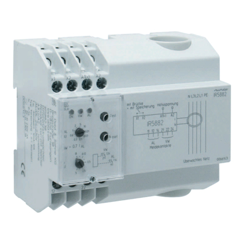
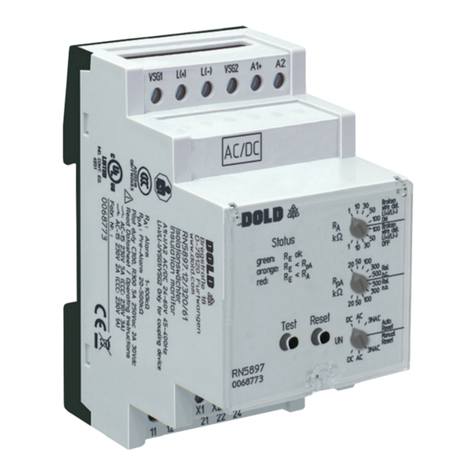
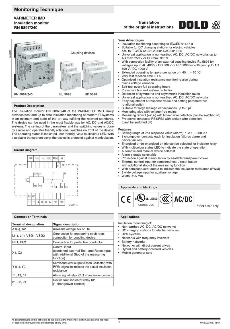
DOLD VARIMETER IMD RN 5897/300 User manual

110.11.23 en / 800A
0274214
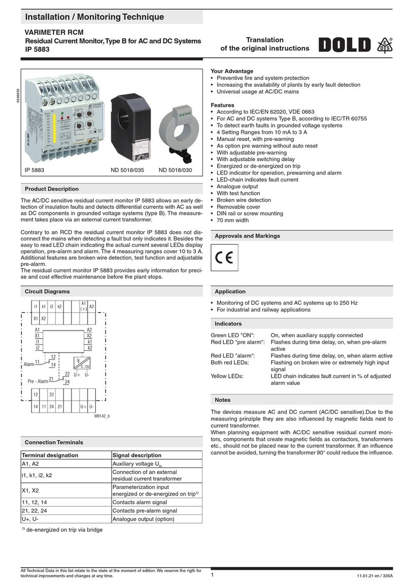
Your Advantages
• FormobilegeneratorsetsaccordingtoDINVDE0100-551
• Preventivereandsystemprotection
• Detectionofsymmetricandasymmetricinsulationfaults
• Universalapplicationinnon-earthedAC,DC,AC/DCnetworks
uptomax.300V
• Easyadjustmentofresponsevaluesandsettingparametervia
rotationalswitch
• Suitableforlargeleakagecapacitancesupto30µF
• Monitoringalsowithvoltage-freemains
• MeasuringcircuitL(+)/L(-)withbrokenwiredetection(canbeswitchedoff)
• ProtectiveconductorPE1/PE2withbrokenwiredetection
(can'tbeswitchedoff)
• Noadditionalcouplingdevicerequired
Features
• InsulationmonitoringaccordingtoIEC/EN61557-8
• 2separateadjustableresponsethresholds
(usinge.g.forpre-AlarmandAlarm)
• Settingrangeof1stresponsevalue(Pre-Alarm):20kΩ…1MΩ
• Settingrangeof2ndresponsevalue(Alarm):10kΩ…250kΩ
• 2changeovercontactsfürinsulationfailures-Pre-Alarmand-Alarm
• Energizedorde-energizedontripcanbeselectedforindicatorrelay
• LEDforstatusindication
• Automaticandmanualdeviceself-test
• Alarmstorageselectable
• Protectionagainstmanipulationbysealabletransparentcover
• ExternalcontrolinputforcombinedTest-/Reset-button
• 3widevoltageinputforauxiliaryvoltage
• Width52.5mm
Product Description
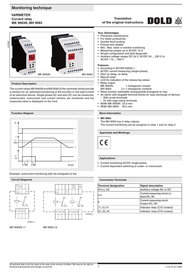
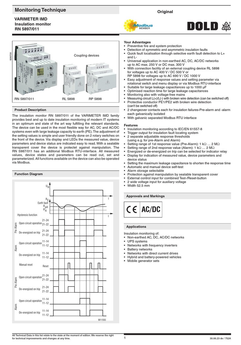
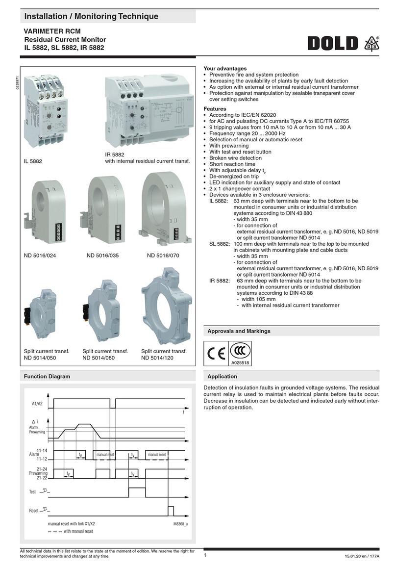
The insulation monitor RN 5897/300 of theVARIMETER IMD family is
a solution for optimal insulation monitoring of modern IT systems.The
device can be used in the most exible way for AC, DC and AC/DC
systems.Theadjustmentofthesettingvaluesissimpleanduserfriendly
doneon3rotaryswitchesonthefrontofthedevice.ViamulticolorLEDthe
devicestatusisindicatedeasytoread.Withasealabletransparentcover
thedeviceisprotectetagainstmanipulation.
Applications
Insulationmonitoringof:
• Non-earthedAC,DC,AC/DCnetworks
• UPSsystems
• Networkswithfrequencyinverters
• Batterynetworks
• Networkswithdirectcurrentdrives
• Hybridandbattery-poweredvehicles
• Mobilegeneratorsets
Monitoring Technique
VARIMETER IMD
Insulation monitor
RN 5897/300
Approvals and Markings
AC/DC
Canada/USA
Translation
of the original instructions
Connection Terminals
Terminal designation Signal description
A1(+),A2 AuxiliarxvoltageACorDC
L(+),L(-) Connectionformeasuringciruit
PE1,PE2 Connectionforprotectiveconductor
X1,X2 Controlinput(combinedexternal
Test-andReset-input)
11,12,14 AlarmsignalrelayK1
(1changeovercontact)
21,22,24 PrewarningsignalrelayK2
(1changeovercontact)
Circuit Diagram
X1 X2
11 12 14 21 22 24 PE1 PE2
A2
A1(+)
L(+) L(-)
22
12
L(+) L(-)
24
14
21
PE2
11
PE1
UH
M11454_a
AllTechnicalDatainthislistrelatetothestateatthemomentofedition.Wereservetheright
fortechnicalimprovementsandchangesatanytime.

210.11.23 en / 800A
ThedeviceissuppliedwithDCauxiliaryvoltageviaterminalsA1(+)/A2.
Switchingontheauxiliaryvoltage(Power-On)isfollowedbyaninternal
self-testfor12sec(see„Devicetestfunctions“).Thetestprocessisvisible
inthestatusLED.Afterthis,measurementoftheinsulationresistance
in the measuring circuits begins and the the colour of the status LED
changestogreen.
Measuring circuit
(Insulation measurement between terminals L(+) / L(-) and PE1/PE2)
TheterminalsL(+)andL(-)areconnecteddirectlytothevoltagesystem
tobemonitored.Abrokenwiredetectioncreatesafaultsignalifthereis
nolow-ohmicconnectionbetweenbothterminals.
Thetypeofnetwork(AC,DC,3NAC)hastobeselected.
AlsotheterminalsPE1andPE2havetobeconnectedwith2separate
wirestotheprotectiveearth.Aninterruptionofawirealsocausesafault
signal(seesection”Behavioronfaultyconnection”).Themonitoringof
thePEconnectioncannotbede-activated.
Tomeasuretheinsulationresistanceanactivemeasuringvoltagewith
changingpolarityisconnectedbetweenL(+)/L(-)andPE1/PE2.
Attheendofameasuringcycletheactualinsulationresistanceisproduced
and indicated. Therelaysforalarm K1andpre-alarmK2switchwhen
d r o p p i n g u n d e r t h e a d j u s t e d r e s p o n s e v a l u e s . I n a d d i t i o n t h e L E D c h a n g e s
toorangecoloronpre-alarmortoredcoloronalarm.
Manual reset of fault message
Therotaryswitch"UN"isdevidedin2sections.Soadditionaltothetypeof
voltagesystemalsomanualorautoresetcanbeselected.(Alarmstoring:
manualreset,noalarmstoring:autoreset).
Ifmanualresetisactivatedtheinsulationfaultsignalsofthemeasuring
circuit are stored when dropping under the adjusted response values
alsoiftheinsulationresistancegoesbacktohealthystate.Pressingthe
„Reset“buttononthefrontsidefor2s,thealarmsignalareresetifthe
actualinsulationresistanceisinhealthystate.
Indicator relay for insulation fault signal
FortheindicatorrelaysK1(contacts11-12-14,foralarm)andK2(contacts
21-22-24,forpre-alarm)thefunctionenergizedontriporde-energizedon
tripcanbesetviapre-alarmrotationalswitch"RpA"whentheinsulation
resistancedropsbelowtheadjustedresponsevalue.
Broken wire detection
A s d e s c r i b e d i n s e c t i o n " M e a s u r i n g c i r c u t ", t h e m e a s u r i n g c i r c u i t s L (+ ) / L ( - )
andtheprotectiveconductorsPE1/PE2areconstantlymonitoredforwire
b r e a k s – n o t o n l y a t P o w e r - O n o r a m a n u a l o r o c c a s i o n a l a u t o m a t i c t e s t . T h e
responsetimeofmonitoringisonlyafewseconds.Brokenwiredetection
betweenL(+)andL(-)isperformedviacoupledalternatingvoltage.This
alternatingvoltageisshort-circuitediftheterminalsareconnectedtothe
connectedmainsatlow-resistance.Thedevicedetectsthatthemainsto
bemonitoredisproperlyconnected.
S i n c e t h i s b r o k e n w i r e d e t e c t i o n i s c a r r i e do u t w i t h a l te r n a t i n g vo l t a g e , l ar g e
c a p a c i t a n c e s s h o u l d b e av o i d e d b e t w e e n L ( +) a n d L ( - ) , s i n c e t h e c a p a c i t i v e
reactanceofthesecapacitancesalsoshort-circuitsthisalternatingvoltage.
ThedevicewouldnolongerdetectaconnectionfaultonL(+)/L(-).
Especiallyparallellinesshouldbeavoidedoverlargerdistances.
I fl ar g erc a pa c i ta n c esb et w e enL (+ ) / L( - )c a nn otb eavo i d e d o ri ft h e c o u p le d
alternatingvoltageinterfereswiththesystem,thebrokenwire detection
canbede-activatedusingalarmrotaryswitch"R
A
".Monitoringdeactivated
or continuous monitoring (every 2 minutes for 10 sec) are the possible
options. If the broken wire detection on L(+)/L(-) is de-activated no AC
voltageisinjected.
ThebrokenwiredetectiononPE1/PE2cannotbede-activated.
Device test functions
Principally,2differenttestfunctionsareimplemented:The"self-test"and
the"expandedtest":
Theself-testofthedeviceisperformedautomaticallyafterPower-Onand
eve r yf ul lo pera tin gh ours. It can al sob etr igger edm anu ally at an yt im eby
pressingthe"Test"buttonatthedevicefrontfor2sec.
W it hth es elf-test ,c o nt rar ytotheex p an d edte st ,t hest at usoft h eI ndi cator
relaysisnotaffected;thesequenceisasfollows:
Theself-testisindicatedviaLEDwithorangeashcode1.Forapprox.
5stonegativetestphase.Withinthese5stheinternalmeasuringcircuit
ischeckedforfailures.Thenthemeasuringpulseisswitchedforapprox.
5stopositivetestphaseandmoreinternalteststakeplace.Ifnofailures
turnedupandhadbeenrecognized,themeasurementcontinuous.The
extendedtestprocedureisstartedwhenduringorattheendoftheabove
describedself-test(12s)thetestbuttonispressedagainfor2s.
Thesequenceissimilartotheself-test(2measuringphasesof5seach)
but in addition the output relays go in alarm stated. The LED shows
orangeashcode2.Thetestphasesoftheextendedtestwillberepeated
continuously.Theextendedtestcanbenishedaftertherstcomplete
sequence(approx.10sec)bypressingthe"reset"buttonfor2seconds.
Thedevicestartstheinsulationmonitoringagain.
Test signal
1)
Reset signal
2)
Relay state K1 and K2
Measuring voltage
Positive
Alarm
No Alarm
Insulation
measurement
Insulation
measurement
Insulation
measurement
3)
4)
Self test (Test 1)
Duration: approx. 12s
Self test (Test 1)
Duration: approx. 12s
Duration: approx. 10s
Continuous extended
test (Test 2)
Negative
M12462
U
t
1)Testsignal:ButtonTest>2sorX1/X2<3s
2)Resetsignal:ButtonReset>2sorX1/X2>3s
3)Toinitiatetheextendedtest(Test2)thetestsignalmustbeoperated
withintheselftest(Test1)again.
4)Theresetsignalhasherenofunction,astherstcompletesequence
ofextendedtest(Test2)isnotnished.
Function
310.11.23 en / 800A
Function Function Diagram
Manual reset
Alarm
Alarm Pre-Alarm Pre-Alarm
Hysteresis function
Reset
21-24
21-24
21-24
21-24
11-14
11-14
11-14
11-14
11-12
11-12
11-12
11-12
Earth fault
E
R
A
RpA
R
21-22
21-22
21-22
21-22
t
t
Open circuit operation
De-energized on trip
UH
M11593
Flashing Codes Status LED
Extended
test
Self test
Connection failure
measuring ciruit L(+)/L(-)
Connection failure
protective conductor PE1/PE2
LED-colour:
Orange
LED-colour:
Red
Internal
system error
M11607
t
Behaviour with internal device faults
Ifinternaldevicefaultsweredetectedduringthetestfunction,theLED
ashescontinuouslyred.TheindicatorrelaysK1andK2switchtothe
alarmstate.
Behavior on faulty connection
WhendetectingbrokenwireonterminalsL(+)/L(-),themeasurementis
disabled.Thereactiontimecouldbeupto2min.Themonitoringrelays
K1andK2goinalarmstate,theLEDindicatestheredashcode1.After
removingtheinterruptionthefaultisautomaticallyreset(max.reactiontime
upto2min)andthemeasurementoftheinsulationresistanceiscontinued.
Stored alarm values remain stored. An interruption of the protective
earthconnectionsPE1/PE2causesthesamereactionasinterruptingthe
measuringcircuit,onlytheLEDindicatetheredashcode2.
External control input
To terminals X1/X2 an external combined Test-/Reset button can be
connected.IftheterminalsX1/X2arebridgedforapprox.1sthetestmode
isstarted.Thishasthesamefunctionaspressingtheinternaltestbutton.
WhenbridgingX1/X2for>3s,astoredalarmwillbereset.Thishasthe
samefunctionaspressingtheinternalresetbutton.
Programming/setting of parameters/set-up of the insulation monitor
Allsettingaredonewith3rotaryswitchesonthefrontoftheunit.Toavoid
u n a u t h o r i z e d m a n i p u l a t i o n of t h e s e t t i n g s , a l l 3 s w i t c h e s a r el o c a t e d b e h i n d
a s e a l a b l e t r a n s p a r e n t c o ve r. T h e r s t r o t a r y s w i t c h “ R A”setstheresponse
valueforalarm.Inadditionitisdividedin2sections.Ifthesettingposition
isintherstsectionthebrokenwiredetectionispermanentenabled,if
thesettingpositionisinthesecondsectionthebrokenwiredetectionis
permanentdisabled.Thesecondrotaryswitch“RpA”setstheresponse
valueforpre-alarm.Inadditionitisalsodividedin2sections.Ifthesetting
positionisintherstsection,therelayoutputfunctionisde-energized
ontrip,ifthesettingpositionisinthesecondsection,therelayoutput
functionisenergizedontrip.
Thethirdrotaryswitch“UN”selectsthetypeofnetworkconnection.Itis
alsodividedin2sections.Ifthesettingpositionisintherstsection,the
unitisonautoreset,ifthesettingpositionisinthesecondsection,the
unitisonmanualreset.
Newsettingsareacceptedwithoutrestartofthedevice.

410.11.23 en / 800A
Indicators
Indicators
Theoperationalstatusofthedeviceisindicatedona3-colourLED:
Off: Noauxiliaryvoltageconnected
Green: Normaloperation(Insulationresistanceinhealthy
state)
Red: Alarm(measuredvaluebelowalarmresponsevalue)
Orange: Warning(measuredvaluebelowpre-alarmresponse
value)
Orange flashing: Testmodeprocedure(seeashingcodediagramm)
Red flashing: Failurecode(seeashingcodediagramm)
Flash code
orange
Status-LED
Description
1
Selftest
(measuringcircuit,measuringvoltage,
internaltests)
2AdvancedTest
(additionalcontrolofindicatorrelays)
Error Indication
Flash code
red
Status-LED
Failure cause Failure recovery
1Brokenwiredetection
onL(+)/L(-).
Check
measuringcircuit
L(+)andL(-)
2Brokenwiredetection
onPE1/PE2.
Check
protectiveearth
connections
PE1andPE2
continously
ashing
Internalfailure
detectedin
testmode
Presstestbuttonagainorrestart
theunitbyinterruptingthe
auxiliarysupplytemporarily.Ifthe
faultremainspermanent,send
devicebacktomanufacturerfor
examination.
continously
ashing
Faultycalibration
valuesdetectedin
devicememory.
Senddevicebacktomanufacturer
forrecalobrationandexamination.
Connection
measuring ciruit
Auxiliary
voltage
Indicator relay
alarm and pre-alarm
Protective
conductor
External
control input
M11609_b
Notes
WARNING
Risk of electrocution!
Danger to life or risk of serious injuries.
• Disconnectthesystemanddevicefromthepowersupplyandensure
theyremaindisconnectedduringelectricalinstallation.
• TheterminalsofthecontrolinputX1-X2havenogalvanicseparationto
themeasuringcircuitL(+)andL(-)andareelectricallyconnectedtogether,
thereforetheyhavetobecontrolledbyvoltfreecontactsorbridge.These
contactsorebridgesmustprovideasufcientseparationdependingon
themainsvoltageonL(+)-L(-).
• PleasedonotconnectexternalvoltagetoterminalsX1/X2.Thecontrol
mustonlybemadebybridgingX1andX2.
!
Attention!
• Beforecheckinginsulationandvoltage,disconnectthemonitoringdevice
RN5897fromthepowersource!
• Inonevoltagesystemonlyoneinsulationmonitorcanbeused.Thishas
tobeobservedwheninterconnectingtwoseparatesystems..
• DeviceterminalsPE1andPE2mustalwaysbeconnectedviaseparate
linestodifferentterminalpointsoftheprotective-conductorsystem.
• ThedevicemustnotbeoperatedwithoutPE1/PE2connection!
• Toensurecorrectmeasurementoftheinsulationresistance,theremust
bealow-impedanceconnection(≤10kΩ)oralow-impedanceinternal
systemresistanceacross the source oracrossthe load between the
measuringcircuitconnectionsL(+)andL(-).
• Toensurecorrectmeasurementoftheinsulationresistance,theremust
bealow-impendanceconnection(≤10kΩ)oralow-impendanceinternal
mains resistance across the source or across the load between the
measuringcircuitconnectionsL(+)andL(-)(orL1(+)andL2(-)when
usingtheballastunit).
nfo
Attention!
• ThemainmeasuringcircuitcanbeconnectedwithitsterminalsL(+)and
L(-)bothtotheDCandalsoACsideofamixednetwork;itisdonemost
practicallywheretheprimaryincomingpowersupplytakesplace e.g.
batterynetworkswithconnectedinvertersontheDCside,withGenerators/
TransformerswithconnectedRectiersorinvertersontheAC-side.To
monitora3NACsystemthedevicecanbeconnectedsinglepole,(L(+)
andL(-)arebridged,totheneutralofthe3p4wsystem.The3phases
havealow-ohmic(approx.3–5Ohm)connectionviathetransformer
windingssoalsoinsulationfailuresofthenotdirectlyconnectedphases
aredetected.Viatherotationalswitch„UN“thecorrecttypeofnetwork
needstobeselected(see„ConnectionExamples“).
• IfamonitoredACsystemincludesgalvanicallyconnectedDCcircuits(e.g.
viaarectier),aninsulationfailureontheDCsidecanonlybedetected
correctly,whenacurrentofmin10mAcanowviathesemiconductor
connections.
• IfamonitoredDCsystemincludesgalvanicallyconnectedACcircuits(e.g.
viaaninverter),aninsulationfailureontheACsidecanonlybedetected
correctly,whenacurrentofmin10mAcanowviathesemiconductor
connections.

510.11.23 en / 800A
General Data
Operating mode: Continuousoperation
Temperature range
Operation:
Auxiliaryvoltage
DC12...24V,
AC/DC24...60V: -40...+70°C
Auxiliaryvoltage
AC/DC85...230V: -40...+60°C
-40...+70°C
(devicemountedwithmin.1cmdistance
toadjacentdevicesordevicewithmax.
2x0.5Acontactcurrent)
Storage: -40...+70°C
Altitude:≤2000m IEC60664-1
Clearance and creepage
distances
Ratedinsulationvoltage: 300V
Overvoltagecategory: III
Ratedimpulsvoltage/
pollutiondegree: IEC60664-1
MeasuringcircuitL(+)/L(-)to
auxiliaryvoltageA1(+)/A2and
indicatorrelaycontactsK1,K2: 4kV/2
AuxiliaryvoltageA1(+)/A2to
indicatorrelaycontactsK1,K2: 4kV/2
IndicatorrelaycontactK1to
indicatorrelaycontactsK2: 4kV/2
Insulationtestvoltage
Routinetest: AC2.5kV;1s
EMC
Electrostaticdischarge(ESD): 8kV(air) IEC/EN61000-4-2
HFirradiation
80MHz…1GHz: 20V/m IEC/EN61000-4-3
1GHz…2.7GHz: 10V/m IEC/EN61000-4-3
Fasttransients: 2kV IEC/EN61000-4-4
Surgevoltage
between
wiresforpowersupply: 1kV IEC/EN61000-4-5
Betweenwireandground: 2kV IEC/EN61000-4-5
HF-wireguided: 20V IEC/EN61000-4-6
Interferencesuppression: LimitvalueclasseB EN55011
Degree of protection
Housing: IP30(notsealed) IEC/EN60529
IP40(sealedwith
sealwire50/30) IEC/EN60529
Theunitmustbe
disconnectedfromthe
powersupplybefore
thesealisapplied
Terminals: IP20 IEC/EN60529
Housing: ThermpolasticwithV0behaviour
accordingtoULsubject94
Vibration resistance: Amplitude0.35mm,
Frequency10...55Hz,IEC/EN60068-2-6
Frequency2...13.2Hz,13.2...100Hz,
acceleration±0.7gn IEC/EN60068-2-6
Shock resistance: 10gn/11ms,3pulsesIEC/EN60068-2-27
Climate resistance: 40/070/04 IEC/EN60068-1
Terminal designation: EN50005
Wire connection DIN46228-1/-2/-3/-4
Crosssection: 0.5...4mm²(AWG20-10)solidor
0.5...4mm²(AWG20-10)
strandedwirewithoutferrules
0.5...2.5mm²(AWG20-10)
strandedwirewithferrules
Strippinglength: 6.5mm
Max.xingtorque: 0.5Nm
Wire fixing: Boxterminalwithcrossrecessscrew
Mounting: DINrail IEC/EN60715
Weight: Approx.200g
Dimensions
Width x height x depth: 52.2x90x71mm
Measuring ciruit L(+) / L(-) to PE1 / PE2
Nominal voltage UN: AC/DC0...230V
Max. voltage range UN: AC/DC0...300V
Frequency range: DCor40...1000Hz
Max. line capacitance: 30µF
Internal resistance (AC / DC): >120kΩ
Measuring voltage: Approx.±90V
Max. mesured current (RE= 0):<0.80mA
Response inaccuracy:±15%±1.5kΩ IEC61557-8
Response value hysteresis: Approx.+25%;min.+1kΩ
On delay
atCE=1µF,
REof∞to0.5*responsevalue: ≤1s(atsetting3NAC)
<5s(atsettingAC,DC)
Measuring time:
atCE=1…30µF,
REfrom∞to1000kΩ,
REfrom∞to100kΩ,
REfrom∞to1kΩ: Seecharacteristics
Response values:
Pre-warning(„RpA“):
kΩ:20 50 100 500 1000
Alarm(„RA“)
kΩ:10 20 50 100 250
Eachadjustableviarotationalswitches
Response value broken
wire detection L(+)/L(-): >Approx.30kΩ
Response value broken
wire detection PE1/PE2: >Approx.0.5kΩ
Auxiliary voltage input A1(+)/A2
Nom. Voltage Voltage range Frequency range
AC/DC24...60V AC19...68V 45…400Hz;DC48%W*)
DC16...96V W*)≤5%
AC/DC85...230V AC68...276V 45…400Hz;DC48%W*)
DC67...300V W*)≤5%
DC12...24V DC9.6...30V W*)≤5%
*)W=Permittedresidualrippleofauxiliarysupply
Nominal consumption:
DC24V,48V: Max.3W
AC230V: Max.3.5VA
Control input X1/X2 for external kombinierte Test-/Reset-Taste
Current flow: Approx.3mA
No-load operation voltage
X1 to X2: Approx.12V
Permissible wire length: <50m
Activation time for test signal:Approx.1s
Activation time for reset signal:>3s
Outputs
Indicator contact: 2x1changeovercontactforAlarm(K1)
andPre-Alarm(K2)
energizedorde-energizedontrip
(programmable)
Thermal current Ith: Max.4A
(seealsoTemperaturerangeOperation)
Switching capacity
toAC15:
NOcontact: 5A/AC230V IEC/EN60947-5-1
NCcontact: 2A/AC230V IEC/EN60947-5-1
ToDC13: 2A/DC24V IEC/EN60947-5-1
Electrical life
at5A,AC230V: 1x10⁵switchingcycles
Short circuit strength
max. fuse rating: 4AgG/gL IEC/EN60947-5-1
Mechanical life: 50x106switchingcycles
Technical Data Technical Data

610.11.23 en / 800A
Standard Types
Temperature range:
Operation: -30...+60°C
Switching capacity: PilotdutyC300,R300
5A250Vac
2A30Vdc
Wire connection: 60°C/75°Ccopperconductorsonly
Torque0.5Nm
Test specification: ANSI/UL60947-1,5thEdition
ANSI/UL60947-5-1,3rdEdition
CAN/CSA-C22.2No.60947-1-13,
2ndEdition
CAN/CSA-C22.2No.60947-5-1-14,
1stEdition
nfo
Technical data that is not stated in the UL-Data, can be found
in the technical data section.
UL-Data
Accessories
Flush mounting kit
Orderreference:KU4087-150/0056598
Foruniversalusewith:
• R-seriesdevicesof
17.5to105mmwidth
• Easymounting
Ordering Example for variants
RN5897.12
/300/61AC/DC24…60V10kΩ-250kΩ20kΩ-1MΩ
SettingrangePre-warning
Settingrangealarm
Auxiliaryvoltage
ULapproval
Variant,ifrequired
Contacts
Type
Vibration and
shock resistance: Category1,ClassB IEC/EN61373
Service temperature classes:OT1,OT2compliant
Protective coating of the PCB: No
Classification to DIN EN 50155
Switching capacity
toAC15
NOcontact: 3A/AC230V
NCcontact: 1A/AC230V
nfo
Technical data that is not stated in the CCC-Data,can be found
in the technical data section.
CCC-Data
RN5897.12/300/61 DC12…24V
Articlenumber: 0067252
• Auxiliaryvoltage: DC12…24V
RN5897.12/300/61 AC/DC24…60V
Articlenumber: 0066942
• Auxiliaryvoltage: AC/DC24…60V
RN5897.12/300/61 AC/DC85…230V
Articlenumber: 0066943
• Auxiliaryvoltage: AC/DC85…230V
• Outputs: 1changeovercontactforpre-warning
1changeovercontactforalarm
• Settingrangepre-warning: 20kΩ…1MΩ
• Settingrangealarm: 10kΩ…250kΩ
• Max.linecapacitance: 30µF
• Energizedorde-energizedontrip
• Selectionoftypeofnetwork
• Width: 52.5mm

710.11.23 en / 800A
Connection Examples
*1)AuxiliaryvoltageUH(A1(+)/A2)canalsobesourcedfromthemonitoredvoltagesystem.
Thevoltagerangeoftheauxiliarysupplyhastobetakenintoaccount.
*2) ControlinputX1/X2forexternalcombinedTest-/Reset-button:
• Controlapprox.1s: Testfunction
• Control>3s: Resetfunction
L1
Single phase mains, isolated from earth
AC 0...300V 40...1000Hz
L2
L(+)
PE
RN5897/300
X1
External combined
Test/Reset button
L(-)
X2 11PE1 12PE2 14 21 22 24
M11627
*2)
A1(+) A2
UH
*1)
Setting of type of network:
AC
UN
L1
Ungrounded mains
3N AC 400V/230V 40...1000Hz
L2
L3
N
L(+)
RN5897/300
X1
External combined
Test/Reset button
L(-)
X2 11PE1 12PE2 14 21 22 24
M11631
*2)
A1(+) A2
UH
*1)
UN
PE
Setting of type of network:
3N AC
L+
Ungrounded DC network
DC 0...300V
L-
L(+)
RN5897/300
X1
External combined
Test/Reset button
L(-)
X2 11PE1 12PE2 14 21 22 24
M11629
*2)
A1(+) A2
UH
*1)
UN
PE
Setting of type of network:
DC

810.11.23 en / 800A
Characteristics
M11611
E. Dold & Söhne GmbH & Co. KG • D-78120 Furtwangen
dold-relays
@dold.com•www.dold.com
• Bregstraße 18 • Phone +49 7723 654-0 • Fax +49 7723 654356
Table of contents
Other DOLD Measuring Instrument manuals

DOLD
DOLD BH 5922 User manual

DOLD
DOLD VARIMETER IMD RN 5897/011 User manual

DOLD
DOLD SAFEMASTER S UH 6932 User manual

DOLD
DOLD RN 5897/240 User manual

DOLD
DOLD SAFEMASTER S LH 5946 User manual

DOLD
DOLD IP 5883 User manual

DOLD
DOLD VARIMETER RCM IL 5882 User manual

DOLD
DOLD SAFEMASTER S UH 5947 User manual

DOLD
DOLD VARIMETER RCM User manual

DOLD
DOLD VARIMETER IMD Series User manual