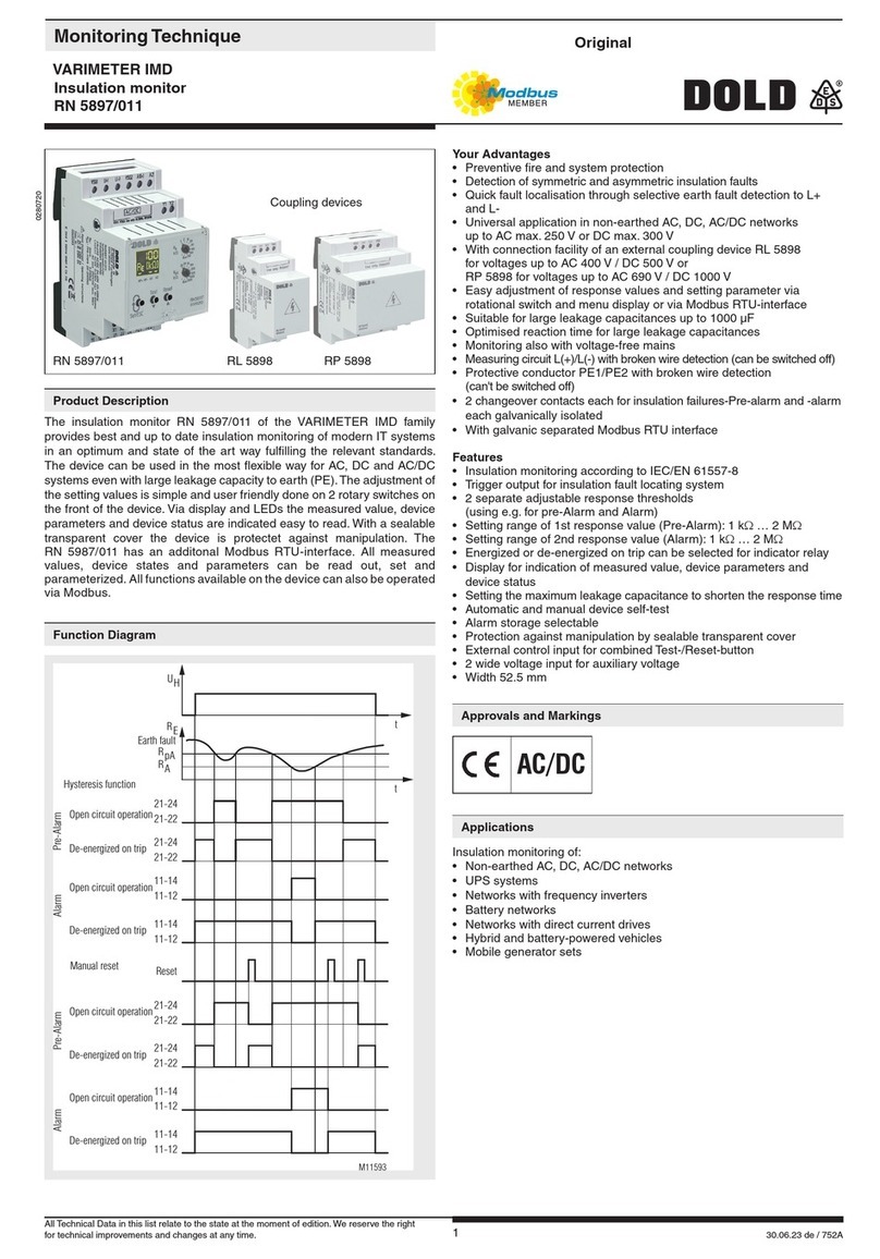
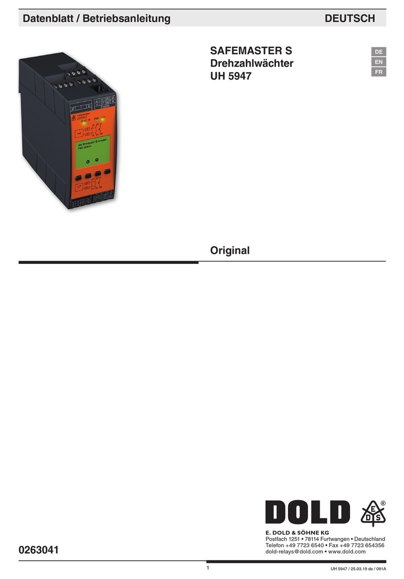
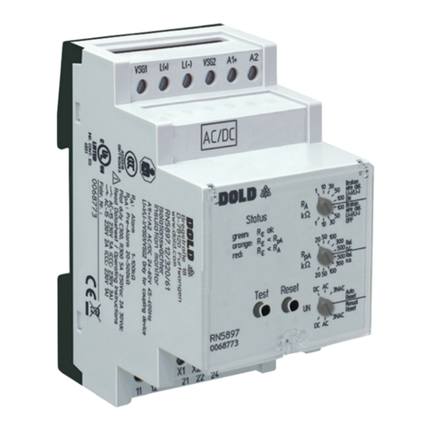
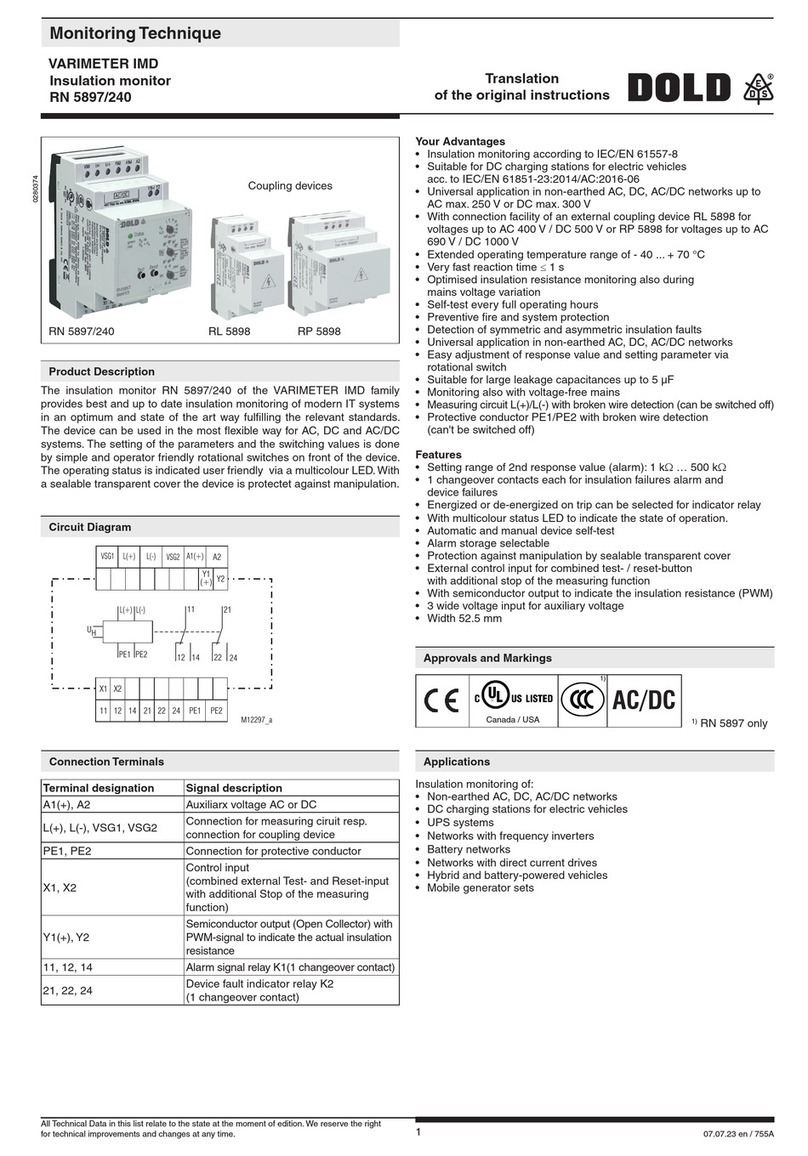
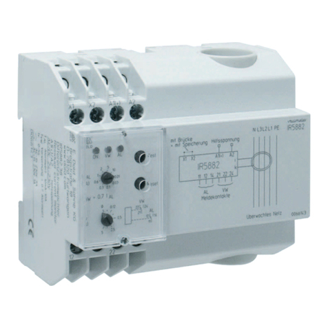
DOLD IP 5883 User manual

111.01.21 en / 335A
Your Advantage
• Preventive fire and system protection
• Increasing the availability of plants by early fault detection
• Universal usage at AC/DC mains
Features
• According to IEC/EN 62020, VDE 0663
• For AC and DC systems Type B, according to IEC/TR 60755
• To detect earth faults in grounded voltage systems
• 4 Setting Ranges from 10 mA to 3 A
• Manual reset, with pre-warning
• As option pre warning without auto reset
• With adjustable pre-warning
• With adjustable switching delay
• Energized or de-energized on trip
• LED indicator for operation, prewarning and alarm
• LED-chain indicates fault current
• Analogue output
• With test function
• Broken wire detection
• Removable cover
• DIN rail or screw mounting
• 70 mm width
0249633
• Monitoring of DC systems and AC systems up to 250 Hz
• For industrial and railway applications
Green LED "ON": On, when auxiliary supply connected
Red LED "pre alarm": Flashes during time delay, on, when pre-alarm
active
Red LED "alarm": Flashes during time delay, on, when alarm active
Both red LEDs: Flashing on broken wire or extremely high input
signal
Yellow LEDs: LED chain indicates fault current in % of adjusted
alarm value
IP 5883 ND 5018/035 ND 5018/030
M9142_b
X1
14 24 U+
i1
12
i2
22
A1
(+)
X2
11 21 U-
k1 k2 A2
A1
X1
i1
i2
k1
k2
A2
X2
11
21
12
22
14
24
Alarm
Pre - Alarm
IF
0...10V
U+ U-
Terminal designation Signal description
A1, A2 Auxiliary voltage UH
i1, k1, i2, k2 Connection of an external
residual current transformer
X1, X2 Parameterization input
energized or de-energized on trip1)
11, 12, 14 Contacts alarm signal
21, 22, 24 Contacts pre-alarm signal
U+, U- Analogue output (option)
1) de-energized on trip via bridge
The AC/DC sensitive residual current monitor IP 5883 allows an early de-
tection of insulation faults and detects differential currents with AC as well
as DC components in grounded voltage systems (type B). The measure-
ment takes place via an external current transformer.
Contrary to an RCD the residual current monitor IP 5883 does not dis-
connect the mains when detecting a fault but only indicates it. Besides the
easy to read LED chain indicating the actual current several LEDs display
operation, pre-alarm and alarm. The 4 measuring ranges cover 10 to 3 A.
Additional features are broken wire detection, test function and adjustable
pre-alarm.
The residual current monitor IP 5883 provides early information for preci-
se and cost effective maintenance before the plant stops.
The devices measure AC and DC current (AC/DC sensitive).Due to the
measuring prinziple they are also influenced by magnetic fields next to
current transformer.
When planning equipment with AC/DC sensitive residual current moni-
tors, components that create magnetic fields as contactors, transformers
etc., should not be placed near to the current transformer. If an influence
cannot be avoided, turning the transformer 90° could reduce the influence.
Installation / Monitoring Technique
VARIMETER RCM
Residual Current Monitor,Type B for AC and DC Systems
IP 5883
Product Description
Circuit Diagrams
Connection Terminals
Approvals and Markings
Application
Indicators
Notes
Translation
of the original instructions
All Technical Data in this list relate to the state at the moment of edition. We reserve the rigth for
technical improvements and changes at any time.

211.01.21 en / 335A
It is of advantage to keep the range small and the Factor high.
Example: Setting 300 mA: Range 0,1 x Factor 3 = 300 mA
The Measuring circuit includes an external residual current transformer.
All conductors of a voltage system are fed through the transformer except
the ground wire. In a healthy system the sum of all flowing currents is zero,
so that no voltage is induced in the CT. If an earth fault occurs, sourcing
a current flowing to ground, the current difference induces a current in
the CT that is detected by the IP 5883. If an earth fault occurs, sourcing a
current flowing to ground, the current difference induces a current in the
CT that is detected by the IP 5883.
On broken sensor wires and broken CT coils the unit goes into alarm state
and the both red LEDs for pre-alarm and alarm flashes.
The unit has 2 changeover output contacts. One for alarm 11, 12, 14 and
21, 22, 24 and one for pre-alarm.
4 Setting Ranges can be slected from 10 mA to 3 A. The fine adjustment
is made via potentiometer „Factor“
Measuring range = Range x Factor.
The alarm relay switches at 100 % of the adjusted response value.
The pre-alarm can be set between 20, 40, 60, 80 and 100 % of the alarm
value.
Via rotary switch „tA“ the time delay of the alarm relay can be adjusted in
2 ranges. Within the chosen range the value is adjusted on rotary switch
„Range“.
tAx 0,1: tA= 0.1 ... 1s ; tAx 1: tA= 1 ... 10s
For the time delay of the pre-alarm 2 settings are available.
tpa = 0 and tpa = 1s
The different CT sizes require a correct adaption of the residual current
monitor. 3 models are available:
Type Frequeny range
Suitable
residual current
transformer
IP 5883 DC + AC up to 250 Hz ND 5018/030
ND 5018/035
IP 5883/070 DC + AC up to 180 Hz ND 5018/070
IP 5883/140 DC + AC up to 60 Hz
ND 5018/105
ND 5018/140
ND 5018/210
Table 1
An external link on X1-X2 allows the change between energized and de-
energized on trip. A change of the function will only be valid after interrup-
tion of the supply voltage.
Terminal X1 / X2: External link = De-energized on trip,
Open = Energized on trip
De-energized on trip: In the case of groundfault or missing auxiliary supply
the relays are de-energized,
the NC contacts 11/12; 21/22 are closed
In fault free state the relays are energized,
the NO contacts 11/14; 21/24 are closed
Energized on trip: In the case of groundfault the relays are energized,
the NO contacts 11/14; 21/24 are closed
In fault free state the relays are de-energized,
the NC contacts 11/12; 21/22 are closed
If an adjusted value is reached on the measuring input (alarm or pre-
warning)at the standard type IP 5883 the signal is stored. Reset is made
by pressing the button „Test/Reset“ for < 3 s s or by disconnecting the
auxiliary supply (approx. 30 s).
If the „Test/Reset“ button is pressed for > 3 s, a test of the unit is made.
The time delays run, the pre-warning and alarm is activated.
An LED chain shows the fault current between 10 and 100 % of the adju-
sted alarm value.
An analogue output 0 ... 10 V indicates also the fault current. 10 V corre-
sponds to 100 % of the adjusted alarm value.
LED "pre-alarm"
LED "Alarm"
LED chain
LED "ON"
Aux.voltage
connected
tA: switching delay alarm (s)
tAx 0,1 tAx 1tA=
tpA: switching delay pre-alarm
tA: switching delay alarm
IpA: prealarm
IpA = tripping value x setting in %
tpA = 0 tpA = 1s
tAx 0,1 tAx 1
IA = Range x Factor [A]
IA: I alarm
M9237_g
Pushbutton
<3s = reset fault memory
>3s = devise test
Set-up and Adjustment Facilities
Function

311.01.21 en / 335A
Input
Auxiliary voltage UH:AC/DC 24 ... 80 V, AC/DC 80 ... 230 V
Voltage range: DC 19 ... 110 V, AC 19 ... 90 V,
DC 64 ... 300 V, AC 64 ... 265 V
Nominal frequency UH:AC 50 / 60 Hz
Nominal consumption
At AC: 5 VA
At DC: 2.5 W
Measuring range: 10 ... 100 mA, 30 ... 300 mA,
100 ... 1000 mA, 300 ... 3000 mA
Measuring range
fine adjustment: 1 ... 10
Max. overload: With overload protection
Pre-warning: 20, 40, 60, 80, 100 %
Frequency range: DC and AC to 250 Hz*)
*) depending on the differential current
transformer used. See „Function“ Table 1.
Repeat accuracy: ≤±3 %
Temperature drift: ≤±0.1 % / K
Reaction time: < 50 ms
Switching delay
pre-warning: Without delay or 1 s adjustable
Switching delay alarm: x 0.1, x 1, fine adjustment 1 ... 10
Output
Contacts: 1 changeover contact for pre-warning,
1 changeover contact for alarm
Thermal current Ith:5 A
Switching capacity
At AC 15:
NO contact: 3 A / AC 230 V IEC/EN 60947-5-1
NC contact: 1 A / AC 230 V IEC/EN 60947-5-1
Electrical life
To AC 15 at 1 A, AC 230 V: 3 x 10⁵switch. cycl. IEC/EN 60947-5-1
Short circuit strength
max. fuse rating: 4 A gG /gL IEC/EN 60947-5-1
Mechanical life: ≥108switching cycles
Analogue Output
Terminal U+ / U-: 0 ... 10 V; 5 mA
If using the analogue output "U+ / U-" you have to use a shielded
cable. The shield has to be grounded one end to PE at the device.
General Data
Operating mode: Continuous
Temperature range
Operation: - 40 ... + 60 °C
Storage: - 40 ... + 70 °C
Altitude: < 2000 m
Insulation coordination
according to IEC 60664-1:
RN 5883 cennected with
current transformer ND 5018
Rated voltage: 800 V
Rated impuls voltage /
pollution degree:
Auxiliary voltage / Meas. circuit: 6 kV / 2
Auxiliary voltage / Contacts: 4 kV / 2
Auxiliary voltage / Analoge output: 6 kV / 2
Contacts / Analoge output: 4 kV / 2
Meas. circuit / Analoge output: 6 kV / 2
Contacts 11,12,14 / 21, 22, 24: 4 kV / 2
EMC
Surge voltages: Class 3 (5 kV / 0,5 J)DIN VDE 0435-303
Electrostatic discharge: 8 kV (air) IEC/EN 61000-4-2
HF-irradiation IEC/EN 61000-4-3, DIN EN 50121-3-2
80 MHz ... 1 GHz: 20 V / m
1 GHz ... 2.7 GHz: 10 V / m
HF-wire guided: 10 V (class 3) IEC/EN 61000-4-6
Fast transients: 2 kV (class 3) IEC/EN 61000-4-4
Surge voltages: 2 kV (class 4) IEC/EN 61000-4-5
Interference suppression: Limit value class B EN 55011
Degree of protection
Housing: IP 40 IEC/EN 60529
Terminals: IP 20 IEC/EN 60529
Housing: Thermoplastic with V0-behaviour
according UL subject 94
Vibration resistance: Amplitude 0.35 mm
frequency 10 ... 55 Hz IEC/EN 60068-2-6
Climate resistance: 40 / 60 / 03 IEC/EN 60068-1
Terminal designation: EN 50005
Wire connection
Cross section: 2 x 2.5 mm2solid or
2 x 1.5 mm2stranded wire with sleeve
DIN 46228-1/-2/-3/-4
Stripping length: 10 mm
Wire fixing: Flat terminals with self-lifting
clamping piece
Fixing torque: 0.8 Nm
Mounting: DIN rail mounting (IEC/EN 60715) or
screw mounting M4, 90 mm hole pattern,
with additional clip available as accessory
Weight: 220 g
Dimensions
Width x height x depth: 70 x 90 x 63 mm
Front detail with potentiometers
M11437
M9467
Example 1
Alarm at 1.5 A (0.3 A x 5)
Time delay alarm:
tA= 1 x 7 s
Pre-warning at
80 % of alarm value, 1.2 A
Time delay pre-warning:
tpa = 0 s
Example 2
Alarm at 100 mA (0.01 A x 10)
Time delay alarm:
tA= 0.1 x 5 s
Pre-warning at
40 % of alarm value, 40 mA
Time delay pre-warning:
tpa = 1 s
Vibration and
shock resistance: Category 1, Class B IEC/EN 61373
Ambient temperature: T1, T2 compliant
T3 and TX with operational limitations
Protective coating of the PCB: No
Settings
Technical Data
Technical Data
Classification to DIN EN 50155 for IP 5883
ET 4086-0-2: Additional clip for screw mounting
Article number: 0046578
Accessories
411.01.21 en / 335A
IP 5883 AC/DC 80 ... 230 V 50 / 60 Hz
Article number: 0058463
• For residual current transformer ND 5018/030 and ND 5018/035
• With pre warning and manual reset
• Energized or de-energized on trip
• Auxiliary voltage UH: AC/DC 80 ... 230 V
• Width: 70 mm
For residual current transformer ND5018/030, ND5018/035:
IP 5883/001: Manual reset,
pre warning with auto reset
For residual current transformer ND5018/070:
IP 5883/070: Pre warning and manual reset
IP 5883/071: Manual reset,
pre warning with auto reset
For residual current transformer ND5018/105,ND5018/140,ND5018/210:
IP 5883/140: Pre warning and manual reset
IP 5883/141: Manual reset,
pre warning with auto reset
Ordering example for variants
IP 5883 /_ _ _ AC/DC 80 ... 230 V 50 / 60 Hz
Nominal frequency
Auxiliary voltage
Variant, if required
Type
Ambient temperature: - 40 ... + 60°C / 253 K ... 333 K
Inflammability class: V0 according to UL94
Insulation coordination according to IEC 61869-1
Highest rated operating voltage Um: AC 720 V
Rated impulse voltage: 3 kV
Length of connection wires
Type of wire to CT, e.g.
Single wire: Up to 1 m
Single wire twisted pair
(pair 1: i1 - k1; pair 2: i2 - k2): Up to 10 m
Screened wire; screen one end grounded to PE at the device: Up to 25 m
Wire cross section: 0,2 ... 1,5 mm2
Stripping length: 8 mm
ND 5018:
Wire fixing: Flat terminals with self-lifting clamping piece
Screw fastening: (only at ND 5018/035, ND 5018/070,
ND 5018/105, ND 5018/140, ND 5018/210) M 5
DIN rail mounting: Using mounting adapter ET 5018
ND 5018/030 Residual Current Transformer
for DIN rail mounting
ND 5018/030 øD øD1 L B A H H1
Dimensions/mm 30 59 55 32 25 87 70
Weight / g 90
ET 5018
D
D1
A
H1
H
H2
B
G
M9213_c
i1 i2k1 k2
DB
L
H
M9777_b
G
Standard Type
Variants
Technical Data Residual Current Monitor ND 5018
Accessories

511.01.21 en / 335A
The residual current transformers ND 5018/035, ND 5018/070, ND 5018/105
can also be mounted on DIN-rail.To do this the metal screw fixings have to
be removed and have to be replaced by 2 mounting clips
(ET5018: art.no. 0058754; set with 2 pcs)
ND 5018/105 øD L B H C D E F k m
Dimensions/mm 105 170 33 146 38 94 46 61 6.5 16
Weight / g 530
ND 5018/140 øD L B H C D E F k m
Dimensions/mm 140 220 33 196 48,5 123 46 61 6.5 16
Weight / g 1250
ND 5018/210 øD L B H C D E F k m
Dimensions/mm 210 299 33 284 69 161 46 61 6.5 16
Weight / g 2100
for screw mounting
ND 5018/035 øD L B H C D E F k m
Dimensions / mm 35 100 33 79 26 48.5 46 61 6.5 16
Weight / g 170
ND 5018/070 øD L B H C D E F k m
Dimensions / mm 70 130 33 110 32 66 46 61 6.5 16
Weight / g 300
Residual Current Monitor ND 5018/035, ND 5018/070,
ND 5018/105, ND 5018/140, ND 5018/210,
DB
m
k
E
F
L
H
M7486
D
C
for DIN rail mounting
ND 5018/035 øD L B H G
Dimensions / mm 35 100 33 79 55
Weight / g 170
ND 5018/070 øD L B H G
Dimensions / mm 70 130 33 110 55
Weight / g 300
ND 5018/105 øD L B H G
Dimensions / mm 105 170 33 146 55
Weight / g 530
Residual Current Monitor ND 5018/035, ND 5018/070, ND 5018/105
DB
L
H
M9777_b
G
Accessories

611.01.21 en / 335A
PE
L1
L2
L3
N
i1 i2k1 k2
X1 X2 11 12 14 21 22 24
A1 A2
IP5883
i1
i2
k1
k2
X1-X2 without bridge:energized on trip
X1-X2 with bridge:de-energized on trip
alarm
output contacts
pre-warning
11 21
M9238_a
12 14 2422
monitored voltage system
PE
PE
PENNL1
L+
L1
L1
L2
L-
L2
L2
L3 L3
L3
M8362_a
Installation of Wires
Connection Examples
E. Dold & Söhne GmbH & Co. KG • D-78120 Furtwangen
dold-relays
@dold.com • www.dold.com
• Bregstraße 18 • Phone +49 7723 654-0 • Fax +49 7723 654356
Other DOLD Measuring Instrument manuals

DOLD
DOLD MK 9063N User manual

DOLD
DOLD SAFEMASTER S LH 5946 User manual

DOLD
DOLD VARIMETER IMD RN 5897/300 User manual

DOLD
DOLD BH 5922 User manual

DOLD
DOLD SAFEMASTER S UH 6932 User manual

DOLD
DOLD VARIMETER RCM User manual

DOLD
DOLD SAFEMASTER S UH 5947 User manual

DOLD
DOLD RN 5897/240 User manual

DOLD
DOLD VARIMETER IMD RN 5897/011 User manual

DOLD
DOLD VARIMETER IMD Series User manual