manuals.online logo
Brands
  1. Home
  2. •
  3. Brands
  4. •
  5. DOLD
  6. •
  7. Measuring Instrument
  8. •
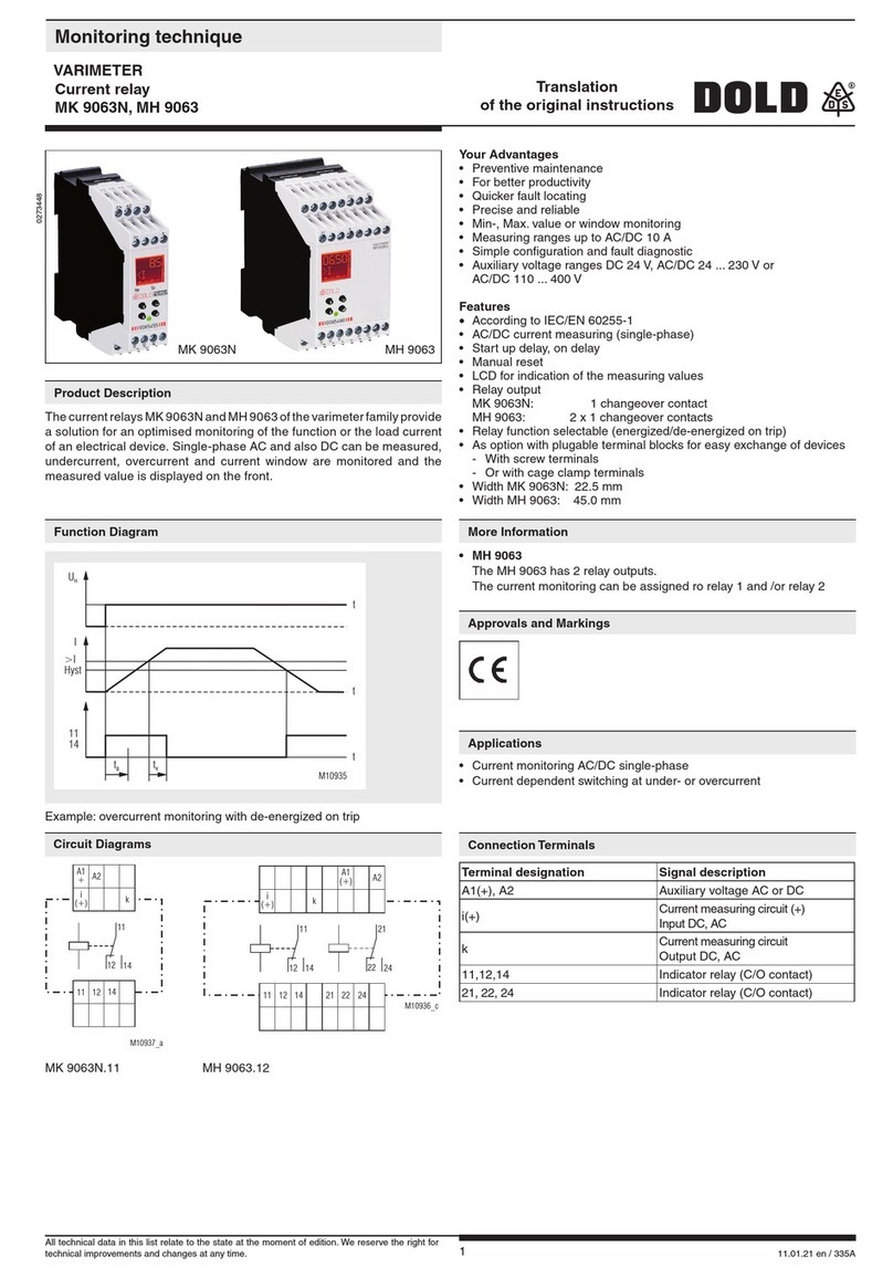
  9. DOLD VARIMETER RCM User manual

DOLD VARIMETER RCM User manual

115.01.20 en / 177A
Your advantages
• Preventive fire and system protection
• Increasing the availability of plants by early fault detection
• As option with external or internal residual current transformer
• Protection against manipulation by sealable transparent cover
over setting switches
Features
• According to IEC/EN 62020
• for AC and pulsating DC currants Type A to IEC/TR 60755
• 9 tripping values from 10 mA to 10 A or from 10 mA ... 30 A
• Frequency range 20 ... 2000 Hz
• Selection of manual or automatic reset
• With prewarning
• With test and reset button
• Broken wire detection
• Short reaction time
• With adjustable delay tv
• De-energized on trip
• LED indication for auxiliary supply and state of contact
• 2 x 1 changeover contact
• Devices available in 3 enclosure versions:
IL 5882: 63 mm deep with terminals near to the bottom to be
mounted in consumer units or industrial distribution
systems according to DIN 43 880
- width 35 mm
- for connection of
external residual current transformer, e. g. ND 5016, ND 5019
or split current transformer ND 5014
SL 5882: 100 mm deep with terminals near to the top to be mounted
in cabinets with mounting plate and cable ducts
- width 35 mm
- for connection of
external residual current transformer, e. g. ND 5016, ND 5019
or split current transformer ND 5014
IR 5882: 63 mm deep with terminals near to the bottom to be
mounted in consumer units or industrial distribution
systems according to DIN 43 88
- width 105 mm
- with internal residual current transformer
0239971
Detection of insulation faults in grounded voltage systems. The residual
current relay is used to maintain electrical plants before faults occur.
Decrease in insulation can be detected and indicated early without inter-
ruption of operation.
Installation / Monitoring Technique
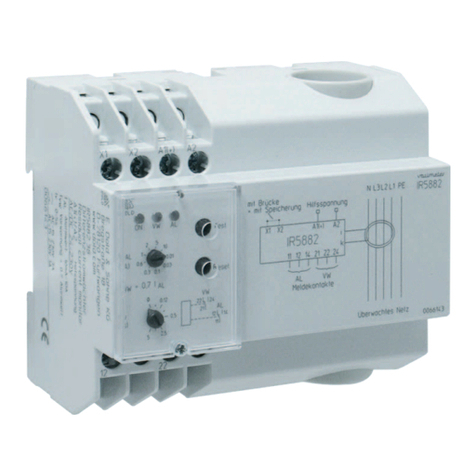
VARIMETER RCM
Residual Current Monitor
IL 5882, SL 5882, IR 5882
Approvals and Markings
ApplicationFunction Diagram
M8368_a
A1/A2
t
Alarm
Prewarning
i
Alarm
Prewarning
11-12
21-22
Test
Reset
manual reset with link X1/X2
with manual reset
11-14
21-24
11-14 tvtv
tv
manual reset manual reset
tv
A025518
IR 5882
with internal residual current transf.
ND 5016/024
IL 5882
ND 5016/035 ND 5016/070
Split current transf.
ND 5014/050
Split current transf.
ND 5014/080
Split current transf.
ND 5014/120
All technical data in this list relate to the state at the moment of edition. We reserve the right for
technical improvements and changes at any time.
215.01.20 en / 177A
LED "ON"
LED "Prewarning"
LED "Alarm"
setting of
alarm value
time delay
for alarm
and prewarning
Reset
button
Test button
M8369_b
green LED "ON": on, when supply connected
red LEDs "VW", "AL": on, when insulation failure (prewarning and
alarm)
If time is set to 0 and a pulsating fault current is flowing (e.g. 1-way rec-
tified) the output relay may flicker because of the short reaction time. By
increasing the time delay this effect can be avoided.
M8349_
a
X1
14
A1
24
i
12 22
X2
11
A2
21
k
A1
X1
ik
A2
X2
11
21
12
22
14
24
AL
VW
A1
X1
PE
A2
X2
4
11
21
12
22
14
24
L1/L2/L3/N
M11134
24
14
22
12
21
11
A2
A1X1 X2
AL
VW
IR 5882
IL /SL 5882
The function of the IL/SL 5882 and IR 5882 can be compared to a fault
current circuit braker unit. It detects and indicates residual currents, but
does not disconnect.
The measurement is done by an external residual current transformer e.
g. ND 5016 which is connected via terminals i and k to the IL/SL 5882.
At the device IR 5882 the residual current transformer is integrated. All
conductors of the voltage system to be monitored are run through the CT
except the ground wire. In a fault free voltage system the sum of all current
is 0 and the CT induces no secondary voltage. If due to an insulation fault
a fault current flows to ground, the current difference in the CT creates a
measuring current, which is detected and measured by the IL/SL 5882 or
IR 5882. Abrokenwire in thesensing circuit would disable themeasurement,
therefore a special circuit detects broken wire and forces the unit to trip.
The unit has 2 x 1 changeover contacts. Contact 11-12-14 for alarm (AL)
and 21-22-24 for prewarning (VW). Prewarning is detected at 70 % of
the selected alarm value. With external bridge X1-X2 the alarm is stored
and has to be reset by pressing the reset button or by disconnecting the
auxiliary supply. Without bridge X1-X2 the unit works with auto-reset and
the fault is not stored. With the button "Test" a fault can be simulated
(Alarm). Each contact is delayed with an adjustable time delay tv(same
delay time for alarm and pre-warning).
To avoid unauthorised adjustment of the potentiometers the unit has a
transparent cover that could be seald with laquer. Two holes above the
push buttons allow activation of test and reset.
Function Connection terminals
Terminal designation Signal description
A1, A2 Auxiliary voltage
i, k (only at IL/SL 5882) Conn. f. external current transformer
ND5016, ND5019 ; terminals i, k
X1, X2 control input
X1/X2 bridged:
with manual reset of alarm
X1/X2 not bridged:
without manual reset of alarm
(Hysteresis function)
11, 12, 14 1. C/O contact (Alarm)
21, 22, 24 1. C/O contact (Pre-warning)
Circuit Diagrams Setting
Note
Indication
315.01.20 en / 177A
Vibration resistance: Amplitude 0.35 mm
frequency 10 ... 55 Hz IEC/EN 60068-2-6
Climate resistance: 20 / 060 / 03 IEC/EN 60068-1
Terminal designation: EN 50005
Wire connection: 2 x 2.5 mm2solid or
2 x 1.5 mm2stranded wire with sleeve
DIN 46228-1/-2/-3/-4
Wire fixing: Flat terminals with self-lifting
clamping piece IEC/EN 60999-1
Fixing torque: 0.8 Nm
Mounting: DIN rail IEC/EN 60715
Weight
IL 5882: approx. 125 g
SL 5882: approx. 150 g
IR 5882: approx. 300 g
Dimensions
Width x height x depth:
IL 5882: 35 x 90 x 63 mm
SL 5882: 35 x 90 x 100 mm
IR 5882: 105 x 90 x 63 mm
(inner diameter current transformer:
21.5 mm or 28 mm)
Input
Auxiliary voltage UH:AC/DC 12 V, AC/DC 24 ... 230 V
Voltage range:
AC: 0.8 ... 1.1 UN
DC: 0.9 ... 1.25 UN
Nominal frequency UH:50 ... 400 Hz
Nominal consumption
AC 230 V: 4 VA
AC 24 V: 1.6 VA
DC 24 V: 1 W
Measuring value adjustable
via rotational switch: AC 0.01; 0.03 A; 0.1 A; 0.3 A; 0.6 A
1 A; 2 A; 5 A; 10 A or
AC 0.01 A, 0.03 A; 0.1 A; 0.3 A; 0.6 A
1 A; 2 A; 7 A; 30 A
Frequency range: 20 Hz ... 2 kHz
at failure current < 50 Hz and the
function "auto reset", a time delay
must be adjusted, so that the relay
does not buzz before switching
Hysteresis: approx. 4% of trip value, fixed
Accuracy: ≤0 ... -30 %
Repeat accuracy: ≤±1 %
Temperature drift: ≤±0.05 % / K
Reaction time: 10 ... 40 ms
Response delay tv: 0 ... 5 s adjustable (logarithmic scale
in order to allow also short time delay
to be adjusted without problems)
Output
Contacts:
IL / SL / IR 5882.38: 1 changeover contact for Prewarning,
1 changeover contact for Alarm
Thermal current Ith:5 A
Switching capacity
to AC 15:
NO contact: 3 A / AC 230 V IEC/EN 60947-5-1
NC contact: 1 A / AC 230 V IEC/EN 60947-5-1
to DC 13:
NO contact: 2 A / DC 24 V IEC/EN 60947-5-1
NC contact: 1 A / DC 24 V IEC/EN 60947-5-1
Electrical life
to AC 15 at 1 A, AC 230 V: 3 x 10⁵switching cycles EN 60947-5-1
Short circuit strength
max. fuse rating: 4 A gG / gL EN 60947-5-1
Mechanical life: ≥108switching cycles
General Data
Operating mode: Continuous
Temperature range
Operation: - 20 ... + 60°C
Storage: - 25 ... + 70°C
Altitude: < 2000 m
Clearance and creepage
distances
rated impulse voltage /
pollution degree
supply / contacts: 4 kV / 2 IEC 60664-1
supply / Measuring Circuit: corresponding to CT
EMC
Surge voltages: class 3 (5 kV / 0.5 J) DIN VDE0435-303
HF-interference: class 3 (2.5 kV) DIN VDE0435-303
Electrostatic discharge: 8 kV (air) IEC/EN 61 000-4-2
HF irradiation IEC/EN 61000-4-3, EN 50121-3-2
80 MHz ... 1 GHz: 20 V / m
1 GHz ... 2,7 GHz: 10 V / m
Fast transients: 4 kV (class 4) IEC/EN 61000-4-4
Surge voltages: 1 kV (class 3) IEC/EN 61000-4-5
HF wire guided: 10 V IEC/EN 61000-4-6
Interference suppression: Limit value class B EN 55011
Degree of protection:
Housing: IP 40 IEC/EN 60529
Terminals: IP 20 IEC/EN 60529
Housing: Thermoplastic with V0-behaviour
according UL subject 94
IL 5882.38 AC/DC 24 ... 230 V 50 / 60 Hz 10 A 5 s
Article number: 0055138
• De-energized on trip
• Auxiliary voltage UH: AC/DC 24 ... 230 V
• Measuring range: 10 A
• Response delay tv: 5 s
• Width: 35 mm
SL 5882.38 AC/DC 24 ... 230 V 50 / 60 Hz 10 A 5 s
Article number: 0055515
• De-energized on trip
• Auxiliary voltage UH: AC/DC 24 ... 230 V
• Measuring range: 10 A
• Response delay tv: 5 s
• Width: 35 mm
IR 5882.38 AC/DC 24 ... 230 V 50 / 60 Hz 10 A 5 s
Article number: 0066743
• Internal residual current transformer (Ø 28 mm)
• De-energized on trip
• Auxiliary voltage UH: AC/DC 24 ... 230 V
• Measuring range: 10 A
• Response delay tv: 5 s
• Width: 105 mm
ND 5016/024
Article number: 0066009
• Residual current transformer for IL/SL 5882
• Diameter: 24 mm
• DIN-rail mounting: waagrecht oder senkrecht
• Screw mounting: M4
IL 5882.12/002: with 2 changeover contacts for alarm
and no pre-warning
Ordering example for variant
IL 5882 .38 /_ _ _ AC/DC 24 ... 230 V 50/60 Hz 10 A 5 s
Response delay
Measuring range
Frequency range
Auxiliary voltage
Variant, if required
Contacts
Type
Technical Data Technical Data
Standard Types
Variant
415.01.20 en / 177A
Ambient temperature
ND 5016: - 20 ... + 60°C / 253 K ... 333 K
ND 5019: - 10 ... + 50°C / 263 K ... 323 K
Inflammability class: V0 according to UL94
Nominal insulation voltage
acc. to IEC 60 664-1: AC 630 V
Rated impulse voltage /
pollution degree: 6 kV/3
Voltage test acc. to
IEC/EN 60 255: AC 3 kV
Transformation ratio: 500 /1
Length of connection wires
Type of wire:
Single wire: up to 1 m
Single wire Twisted pair: up to 10 m
Screened wire;
screen on terminal k: up to 25 m
Wire cross section
ND 5016: 0.2 ... 1.5 mm2
ND 5019: 0.75 mm2
Stripping length: 8 mm
Wire fixing
ND 5016: Terminals with spring connection and
direct (Push in) technology
ND 5019: Box terminals
Screw connection:
ND 5016: M3 or M4
ND 5019: M5
Fixing torque: 0.8 Nm
DIN rail mounting:
ND 5016/024, /035: integrated clips for vertical and
horizontal mounting
ND 5016/070: integrated clips for horizontal mounting
ND 5019: using mounting adapter ET 5018
for DIN rail mounting or screw mounting
Residual Current Transformer ND 5016/024, ND 5016/035
ND 5016/024 øD L L1 B H C E F k
Dimension/mm 24 82 75 24 54 25 42* 46 4,2
Weight / g approx. 80
Article number 0066009
ND 5016/035 øD L L1 B H C E F k
Dimension/mm 35 88 81 24 67 25 42* 46 4,2
Weight / g approx. 90
Article number 0067064
*)Drill tolerance for screw mounting: ± 0.5 mm
for DIN rail mounting or screw mounting
ND 5016/070 øD L H H1 B C F k E G
Dimension/mm 70 111 110 115 32 37 55 4,2 50* 74*
Weight / g approx. 220
Article number 0067065
*)Drill tolerance for screw mounting: ± 0.5 mm
Residual Current Transformer ND 5016/070
Accessories
Technical Data Residual Current Transformer ND 5016, ND 5019
High forces when mounting may damage the current transformer fixtures.
The fixing clips are designed to support the current transformer. Forces
that are applied by the cable running through the current transformer can
only be tolerated within limitations.
During installation and afterwards please make sure that the wires are
led through the current transformer without applying pressure and remain
stable in that position.
Mounting instructions for screw mounting
M10979_b
B
E
F
k
D
H
L1
L
C
B
E
F
k
D
H
H1
L
CC
G
M11582_a
515.01.20 en / 177A
Accessories
Residual Current Transformer ND 5019
for Screw connection
The residual current transformer ND 5019/105 can also be mounted on
DIN-rail. To do this the metal screw fixings have to be removed and have to
be replaced by 2 mounting clips (ET5018: art.no. 0058754; set with 2 pcs)
Dimensions in mm
ND 5019/105
øD 105
L 170
B 33
H 146
C 38
D 94
E 46
F 61
k 6,5
m 16
Weight
ND 5019/105
kg 0,5
Art-Nr. 0055118
M11123
M11583
Disassembling ND 5016/024 and ND 5016/035
Disassembling ND 5016/070
DB
m
k
E
F
L
H
M7486
D
C
DB
L
H
M9777_b
G
615.01.20 en / 177A
Dimensions
ND 5014/050 A B C D E F
Dimension/mm 160 49 30 77 200 116
Weight / g approx. 380
Article number 0068614
ND 5014/080 A B C D E F
Dimension/mm 204 79 30 108 260 156
Weight / g approx. 850
Article number 0068613
ND 5014/120 A B C D E F
Dimension/mm 252 119 30 149 328 204
Weight / g approx. 1500
Article number 0068565
*)Drill tolerance for screw mounting: ± 0.5 mm
M12059
100
6,4
Ambient temperature: - 40 ... + 80°C / 233 K ... 353 K
Inflammability class: V0 according to UL94
Insulation coordination according to IEC 61869-1
Highest rated operating voltage Um: AC 720 V
Rated impulse voltage: 3 kV
Rated impuls voltage / pollution degree: 8 kV / 3
Rated transformation ratio: 500 / 1
Rated primary current: 10 A
Nominal load: 50 mVA
Accuracy: Class 3
Wire connection
Wire cross section: 0.2 ... 2.5 mm2 rigid /
0.2 ... 2.5 mm2flexible / AWG 24 ... 12
Stripping length: 6 mm
Wire fixing: Terminals with spring connection and
direct (Push in) technology
Actuating force: 40 N max.
Mounting
DIN rail mounting: vertical and horizontal mounting
on enclosed socket
ND 5014/120: screw fastening also possible
Technical Data Residual Current Monitor ND 5014
Residual current monitor ND 5014/050, ND 5014/080, ND 5014/120
715.01.20 en / 177A
Mounting - Srew fixing at ND 5014/120
To high forces applied during installation can damage the transformer on
the mounting foots.
The mounting foots are only designed to fix the transformer. Forces that are
applied to the CT by the conductors can only be supported within limitations.
When installing the CT, the conductors should be lead free through the
transformer and should later stay in that position.
Mounting instructions for srew fixing
Wiring Information Residual Current Monitor
Screws are not included in the delivery !
For further details see separate data sheet ND 5014
The hinged cover protects the push-in terminal block and avoids unin-
tended disconnection of the wiring
The push-in terminal block provides easy mounting
Stripping length: 10 mm
Connecting capacity: 0.2 .... 2.5 mm2



815.01.20 en / 177A
PE
PE
PENNL1
L+
L1
L1
L2
L-
L2
L2
L3 L3
L3
M8362_a
M8363
Attention:
As the auxiliary supply has no galvanic separation, the se-
condary circuit of the CT must not be connected to ground.
A ground connection will lead to a damage of the unit!
PE
L1
L2
L3
N
ik
X1 X2 11 12 14 21 22 24
A1 A2
IL5882
ik
X1-X2 open : automatic reset
X1-X2 closed : manual reset
* only IL5882, SL5882
Alarm
signalling contacts
Prewarning
11 21
M8370_c
12 14 2422
monitored voltage system
*
Installation of Wires
To Avoid Interference with High Starting Currents
Connection Example
E. DOLD & SÖHNE KG • D-78114 Furtwangen
e-mail: dold-relays
@dold.com • internet: http://www.dold.com
•
POBox1251•Telephone(+49)77 23 / 654-0 • Telefax (+49) 77 23 / 654-356

This manual suits for next models

13

Other DOLD Measuring Instrument manuals

DOLD VARIMETER IMD RN 5897/300 User manual

DOLD

DOLD VARIMETER IMD RN 5897/300 User manual

DOLD IP 5883 User manual

DOLD

DOLD IP 5883 User manual

DOLD VARIMETER IMD RN 5897/011 User manual

DOLD

DOLD VARIMETER IMD RN 5897/011 User manual

DOLD VARIMETER IMD Series User manual

DOLD

DOLD VARIMETER IMD Series User manual

DOLD MK 9063N User manual

DOLD

DOLD MK 9063N User manual

DOLD BH 5922 User manual

DOLD

DOLD BH 5922 User manual

DOLD VARIMETER RCM IL 5882 User manual

DOLD

DOLD VARIMETER RCM IL 5882 User manual

DOLD SAFEMASTER S UH 5947 User manual

DOLD

DOLD SAFEMASTER S UH 5947 User manual

DOLD SAFEMASTER S UH 6932 User manual

DOLD

DOLD SAFEMASTER S UH 6932 User manual

DOLD RN 5897/240 User manual

DOLD

DOLD RN 5897/240 User manual

DOLD SAFEMASTER S LH 5946 User manual

DOLD

DOLD SAFEMASTER S LH 5946 User manual

Popular Measuring Instrument manuals by other brands

YOKOGAWA SC4A instruction manual

YOKOGAWA

YOKOGAWA SC4A instruction manual

Keysight N1914A datasheet

Keysight

Keysight N1914A datasheet

sparklike Handheld instruction manual

sparklike

sparklike Handheld instruction manual

Sartorius LMA200PM operating instructions

Sartorius

Sartorius LMA200PM operating instructions

Martek Mark 25 instruction manual

Martek

Martek Mark 25 instruction manual

KING 7430 Series installation instructions

KING

KING 7430 Series installation instructions

Chelonia F-POD user guide

Chelonia

Chelonia F-POD user guide

BRIDEX Rudolf R-DPA96 A instruction manual

BRIDEX

BRIDEX Rudolf R-DPA96 A instruction manual

ABB DATUM L160 user guide

ABB

ABB DATUM L160 user guide

Ammeter EPM-14 manual

Ammeter

Ammeter EPM-14 manual

Omega DP25B-S Quick start quide

Omega

Omega DP25B-S Quick start quide

Raycus RFL-C Series user guide

Raycus

Raycus RFL-C Series user guide

SICK WebChecker MLG-2 quick start guide

SICK

SICK WebChecker MLG-2 quick start guide

WIKA IBF1 operating instructions

WIKA

WIKA IBF1 operating instructions

Kvarta SMART PENGUIN user manual

Kvarta

Kvarta SMART PENGUIN user manual

Rae AutoRAE Lite user guide

Rae

Rae AutoRAE Lite user guide

Pira P275E user guide

Pira

Pira P275E user guide

Sper scientific 850081 instruction manual

Sper scientific

Sper scientific 850081 instruction manual

manuals.online logo
manuals.online logoBrands
  • About & Mission
  • Contact us
  • Privacy Policy
  • Terms and Conditions

Copyright 2025 Manuals.Online. All Rights Reserved.