Temperature-Controlled Breadboard Chapter 4: Operation
Page 4 CTN012640-D02
Chapter 4 Operation
4.1. Starting the Device
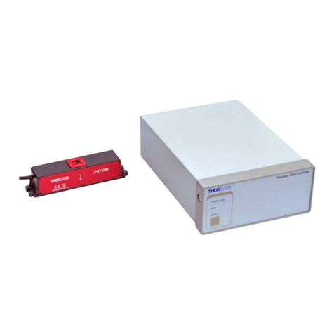
The front and back panels of the PTC1(/M) are shown in Figure 1. Make sure the device is connected to the
power supply which is connected to a socket outlet with proper grounding protection.
After the device is turned on, the LED on the front panel will show the state of the device.
4.2. LED Indicator
The LED indicator (F5 in Figure 1) has three possible colors indicating the current status of the device:
1. Green: the temperature has reached the target and stabilized. By default, the unit achieves this status
when the temperature reaches within ±0.1 °C of the target temperature. The value of this tolerance can
be set using the PTC1(/M) software, included with the device.
2. Yellow: indicates one of the following conditions:
a) The device is working properly but the temperature has not reached the target.
b) No sensor is detected; the device has been switched to external sensor mode and no sensor is
connected.
3. Red: there are errors in the device the operation has been stopped. When an error occurs, it may be
due to one of the following reasons:
a) The device is overheated.
b) Other defective electronics in the device.
4.3. Panel Operation
After switching on the device, set the “MODE” toggle switch to “KNOB” and the “SENSOR” toggle switch to
“INT”. Then use the knob to tune the target temperature of the breadboard.
After the unit reaches the target temperature and stabilizes, the LED indicator will turn green.
4.4. Software Operation
Set the “MODE” toggle switch to “USB” and connect the device to a computer with the included USB cable. The
device can be controlled by the PTC1 software, included with the device.
With the software, users can set the target temperature with higher resolution. The user can also see a precise
readout of the temperature detected by the internal or external sensor. The temperature stabilization window
and PID settings of the device can also be fine-tuned.
In this mode, the device will not respond to any adjustment on the knob.
4.5. Connecting an External Sensor
On the front panel of the PTC1(/M), there is a 2.5 mm Stereo Earphone Jack (F2 in Figure 1). It is designed to
accept a Thorlabs TSP-TH temperature probe as an external sensor.
Connect the TSP-TH and toggle the “SENSOR” swtich to “EXT”. Then the PTC1(/M) will use the external
thermistor as the temperature monitor for its TEC control feedback loop instead of the internal thermistor in the
breadboard.
