Table of Contents
Introduction ............................................................................................4
Congratulations
......................................................................................5
Acronyms and Definitions .........................................................................5
Safety .........................................................................................................5
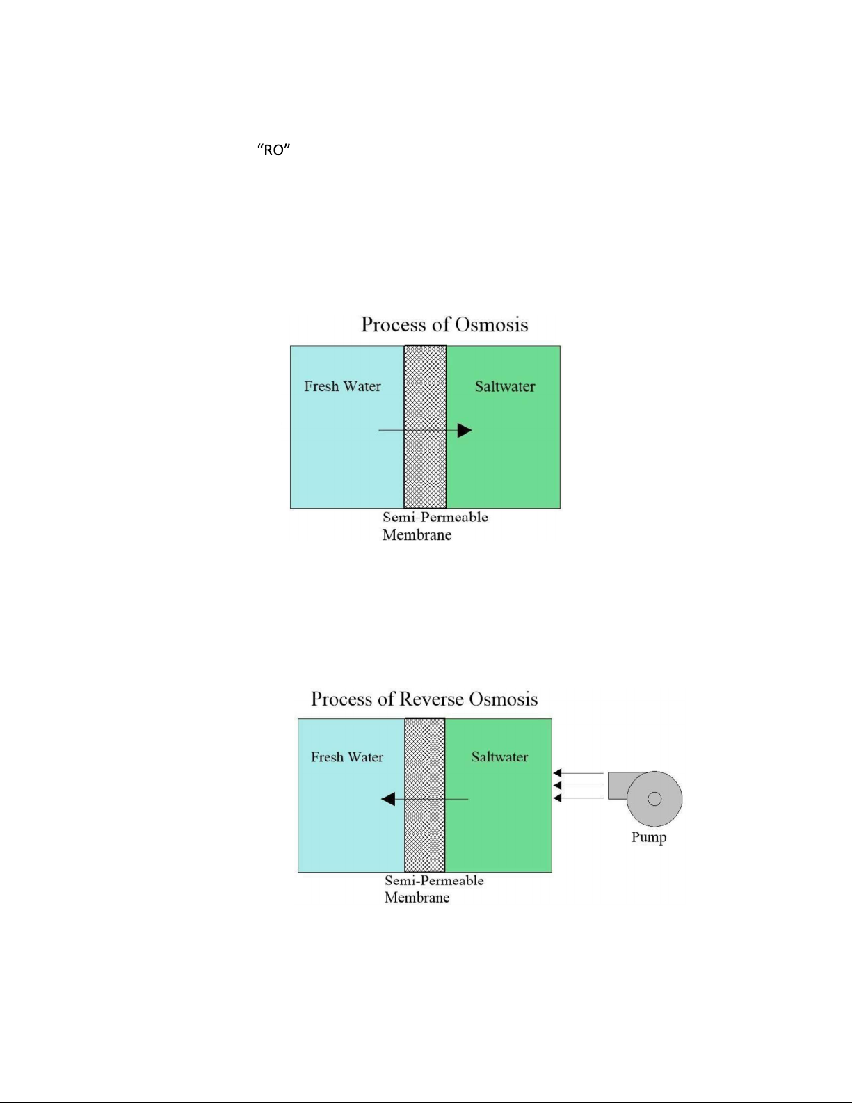
Principles of Reverse Osmosis
..............................................................6
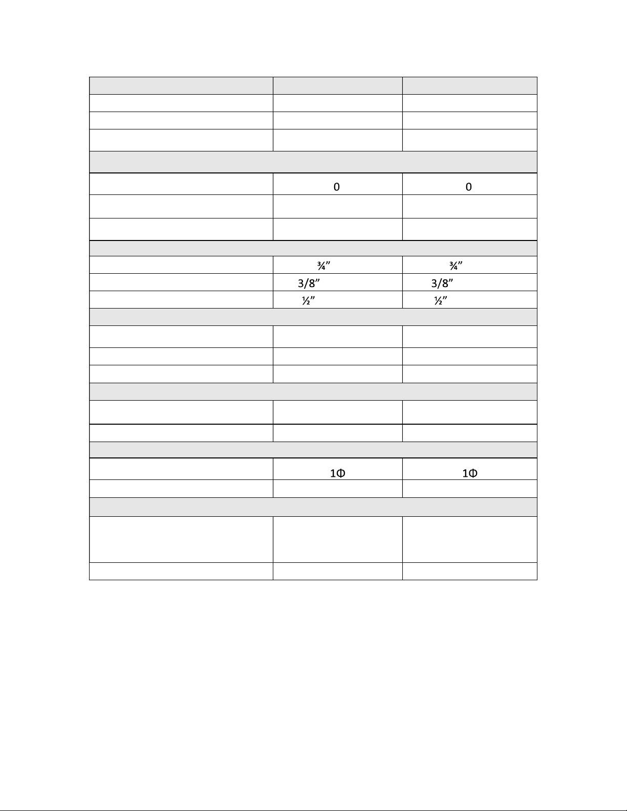
Unit Specifications .....................................................................................7
Installation and Commissioning ................................................................8
SZIII Install Kit ............................................................................................9
System Requirements and Operation Guidelines .................................. 10
Plumbing .......................................................................................... 10
Tube Cutting and Installation Procedure for Quick Connect Fittings 10
Electrical ........................................................................................... 11
SZIII Wiring Diagram
............................................................................ 12
SZIII One Line Flow Diagram
.............................................................. 13
PRE-FILTRATION ............................................................................... 14
Pre-Filtration Plumbing .................................................................... 14
Overboard Connection ..................................................................... 15
Product to Tank Connection ............................................................. 15
Feed From Watermaker ................................................................... 16
Membrane Supply ............................................................................ 16
Membrane Return ............................................................................ 17
Membrane Product .......................................................................... 17
Operation and Maintenance .................................................................. 18
Operation Specifications ........................................................................ 19
Feed Water Specifications
........................................................... 19
System Standard Operating Parameters ................................................ 20
TEMPERATURE CORRECTION FACTORS FOR MEMBRANE
PRODUCTION ................................................................................... 21
Rejection, Recovery, and Flow Rates ............................................... 22
Components of the SZIII Unit ................................................................. 23
System Controller ............................................................................. 23
Freshwater RO Pump ....................................................................... 23
Membranes ...................................................................................... 23
Membrane Operation Guidelines .................................................... 23