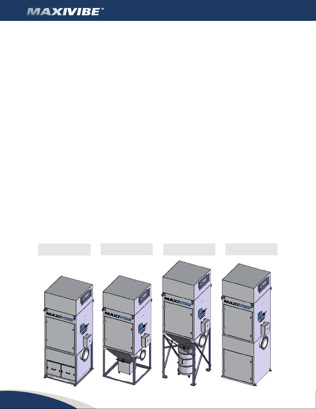
Shaker type dust collector
22
INDEX
................................................. 3
................................ 3
................................................. 4
3.1 Each MAXIVIBE units include...................................... 4
.................................................. 5
................................................. 5
.................................. 5
6.1 Automacshaker(oponal) ...................................... 5
6.2 Manualshaker ................................................. 5
.................................................. 6
7.1 Inspeconofthematerial ....................................... 6
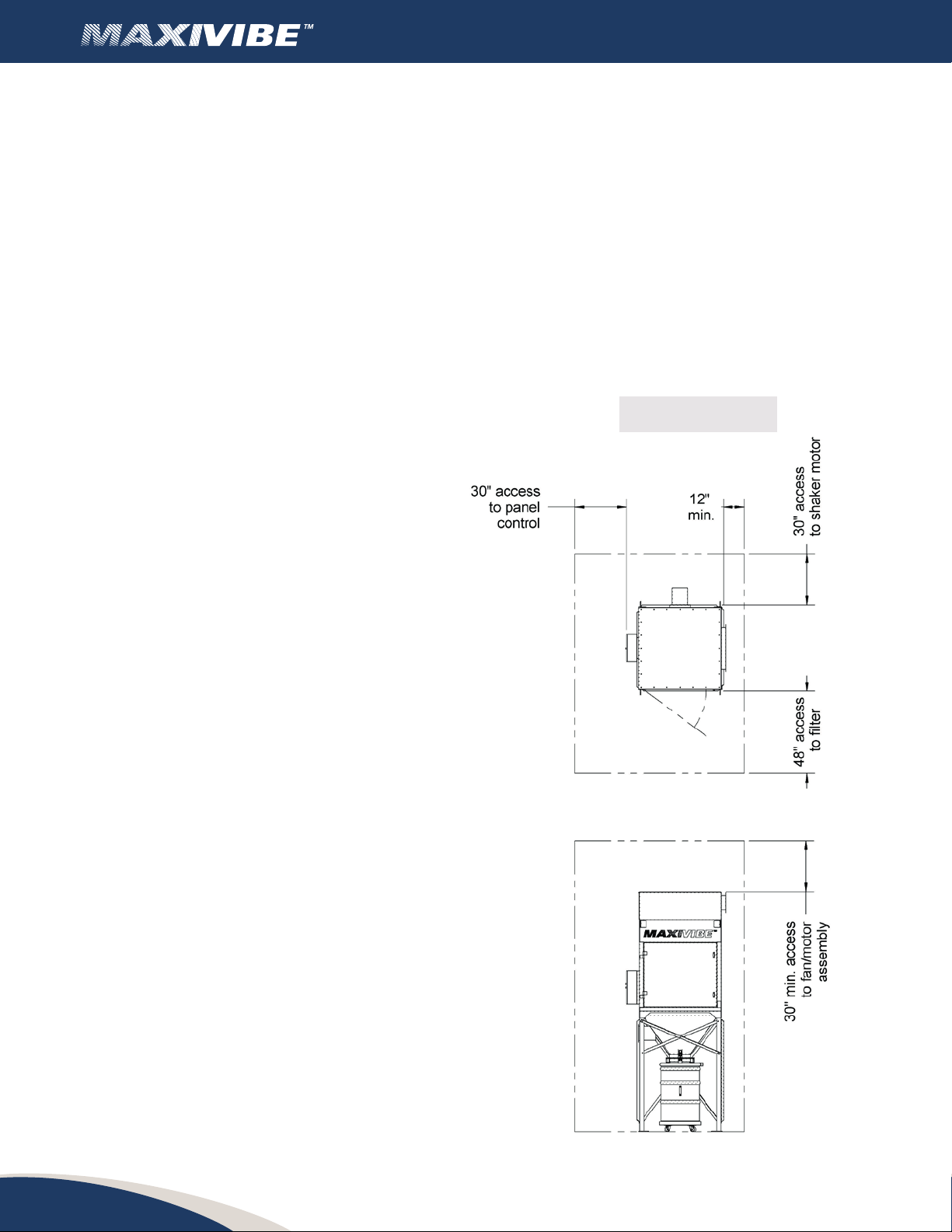
7.2 Areaofinstallaon .............................................. 6
.................................................... 7
8.1 Necessarytools ................................................ 7
8.2 Fing......................................................... 7
.......................................... 9
.............................................. 11
.................................................... 11
11.1 Checklist ..................................................... 11
11.2 Shakersystem.................................................. 11
11.3 Electricalconnecon ............................................ 11
......................................... 12
12.1 Starngtheunitwithanewlterenvelope ......................... 12
12.2 Normalstart-up ................................................ 12
12.3 ShungtheunitOFF ............................................ 12
.............................................. 12
13.1 Workers/Sta .................................................. 12
13.2 Electricalcomponents ........................................... 12
13.3 Explosivedusts ................................................. 12
13.4 Anchors ....................................................... 13
13.5 Interiorinstallaon.............................................. 13
13.6 Processescreangsparks ........................................ 13
................................................. 13
14.1 Replacingthelterenvelope ..................................... 13
14.2 Installaonofthelterenvelope .................................. 14
14.3 Controlpanel .................................................. 15
14.4 Programminginstrucons ........................................ 15
............................................... 15
................................... 16
.............................................. 16
.................................................... 19
.......................................... 20
................................................. 20
............................................... 20