Donaldson DFOI4 User manual

本手册中,指示为避免设
备故障所必须采取的预
Installation and Operation Manual
Installation, Operation and Maintenance Manual
DFOI3, DFOI4 & DFOI6
Throughout this manual statements
indicating precautions necessary to
avoid equipment failure are referenced in a
Note. Statements indicating potential hazards
that could result in personal injury or property
damage are referenced in a CAUTION! box.
Donaldson Company reserves the right to change design
and specifications without prior notice.
Illustrations are for reference only as actual product may
vary. IOM AK0301701
Revision 2
DFOI4
DFOI6
DFOI3

唐纳森(无锡)过滤器有限公司
Donaldson (Wuxi) Filters Co.,Ltd.
CAUTION!
Application of Dust Control Equipment
•Combustible materials such as buffing lint, paper, wood, aluminum or steel
dust, weld fume, or flammable solvents represent fire or explosion hazards.
Use special care when selecting and operating all dust or fume collection
equipment when combustible materials are present to protect workers and
property from damage due to fire and/or explosion. Consult and comply with
National and Local Codes relating to fire or explosion and all other appropriate
codes when determining the location and operation of dust or fume collection
equipment.
•When combustible materials are present, consult with an installer of fire
extinguishing systems familiar with these types of fire hazards and local fire
codes for recommendations and installation of fire extinguishing and explosion
protection systems. Donaldson Torit dust collection equipment is not equipped
with fire extinguishing or explosion protection systems.
• DO NOT allow sparks, cigarettes or other burning objects to enter the hood or
duct of any dust or fume control equipment as these may initiate a fire or
explosion.
• For optimum collector performance, use only Donaldson Torit replacement
parts.
Warning – Improper operation of a dust control system may contribute to
conditions in the work area or facility that could result in severe personal injury
and product or property damage. Check that all collection equipment is properly
selected and sized for the intended use.
2

DFOI
Table of contents List of figures
1.0 Product Introduction …………………….6 Figure 1: Schematic
2.0 Installation ……………………………….6 Figure 2: Operational Schematic
3.0 Start up and Operation …………………7 Figure 3: Inlet Schematic
4.0 Service …………………………………...8 Figure 4: Dust Removal for Dust Disposal
System
5.0 Trouble Shooting ………………………...9 Figure 5: Exchanging Filter Element
6.0 Control Panel ……………………………11 Figure 6: Control Panel
7.0 Spare Parts ………………………………15 Figure 7: Electrical Terminal Block
Figure 8: Wiring Diagram
Data Sheet
Model Number __________________________Serial Number_____________________________
Ship Date _______________________________Installation Date __________________________
Customer Name________________________________________________________________
Address _______________________________________________________________________
_______________________________________________________________________
Filter Type _____________________________________________________________________
Accessories_____________________________________________________________________
Other _________________________________________________________________________
This manual contains specific precautionary statements relative to worker safety. Read
thoroughly and comply as directed. Discuss the use and application of this equipment
with a Donaldson Torit representative. Instruct all personnel on safe use and
maintenance procedures.
3

唐纳森(无锡)过滤器有限公司
Donaldson (Wuxi) Filters Co.,Ltd.
DFOI4
DFOI6
DFOI3
Figure 1
Schematic
1. Lift bar
2. Filter access cover
3. Dust drawer
4. Control panel
5. Access door
6. Inlet
7. Access hole
8. Damper
9. Cable gland
10. Compressor connector
11. External spark trip
4

DFOI
Figure 2
Operational Schematic
Operation Filter element cleaning
4. Clean air outlet
5. Manifold
6. Diaphragm valve with built on
solenoid valve
7. Tube sheet
8. Air pulse
9. Dust (falling)
1. Dirty air inlet
2. Filter element
3. Hopper
5

唐纳森(无锡)过滤器有限公司
Donaldson (Wuxi) Filters Co.,Ltd.
1.0 Product Introduction
The dust collector is used for the collection of
airborne dust and particulate. Whether in
answer to the problem of air pollution, or as
part of a manufacturing process, the dust
collector provides highly efficient and
continuous on-line dust collection.
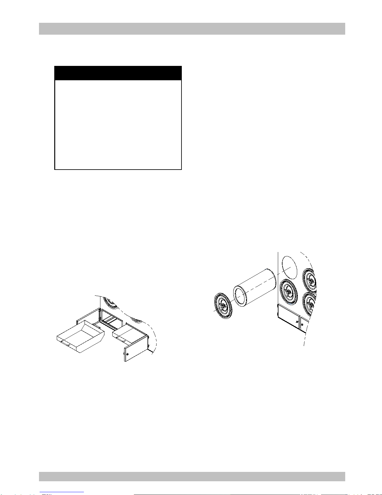
The filter elements are the heart of the dust
collector. These filter elements help ensure
the only cleaned air is returned to the plant
environment.
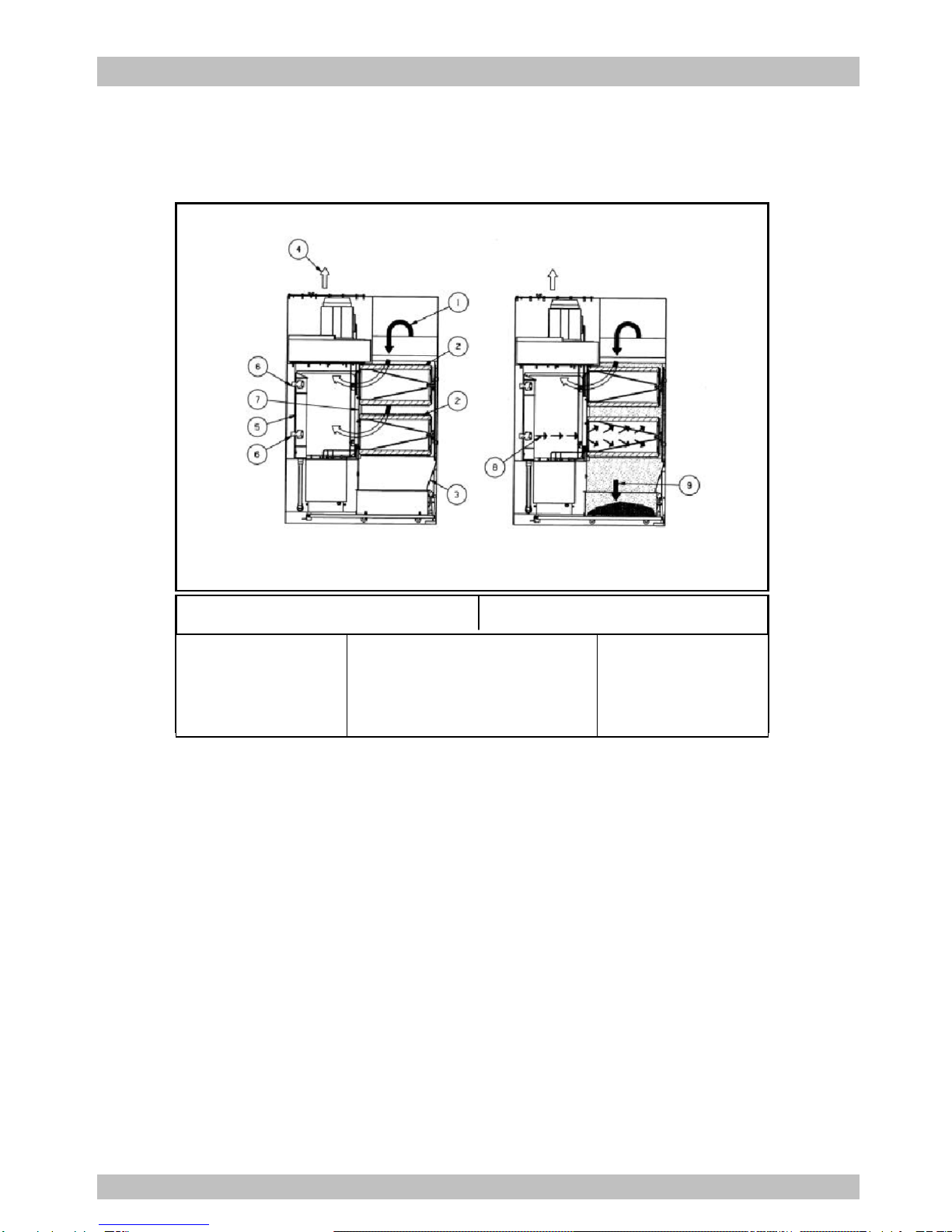
During operation, contaminated air enters the
dust collector through the dirty air inlet area
and passes through the filter elements. Dust
is collected on the surface of the filter
elements. The filtered air flows through the
centre of the filter elements into the clean air
chamber, where it exhausts through the
clean air outlet re-circulated into the
environment.
To ensure the optimal performance of your
dust collector it is necessary that the filter
elements are cleaned automatically
sequentially. During the filter sequence, the
timer energizes a solenoid valve, causing the
corresponding diaphragm valve to send a
pulse of compressed air through the filter
elements (from the inside outwards),
removing the collected dust from the outside
surface of the filter elements. The dust falls
through the hopper into the dust disposal
system.
2.0 Installation
Ensure all persons carrying out work on the
supplied equipment follow any relevant
recognized standards or codes and are
competent to do so.
2.1 Compressed Air Connection
Compressed air pressure must be at 6 bar.
Be sure that all compressed air components
are adequately sized to meet the maximum
system requirements of 45 Nliters per pulse
at 6 bar supply pressure (= design pressure).
Compressed air supply has to be both oil and
moisture free.
Connect the compressed air supply line to
the compressed air connection of the dust
collector.
A compressed air shut-off valve, a filter/water
separator with automatic condense drain, a
pressure regulator with gage must be
installed on the compressed air supply line.
2.2 Electrical Connection
Enter the cable through the cable gland
locate at the lower right corner of the
collector. And enter the cable to the control
box through the cable gland locate at the
bottom of the enclosure. Please follow the
electrical diagram provided for connection.
Do not install in classified hazardous
atmospheres without an enclosure rated for
the application.
6

DFOI
Figure 3
Inlet Schematic
2.3 Inlet Duct Connection
The inlet duct is sent loose with the unit.
Connect it to the inlet flange with self-tapping
screws as shown on figure 3. All connections
have to be sealed properly.
3.0 Start-up and Operation
Check that the outlet of the fan is free of
debris before starting.
Make sure the dust disposal system is
properly installed under the hopper.
With new filter elements the airflow should be
adjusted to the nominal value by closing the
damper valve.
Check if the access doors are closed.
Switch main power on and press
switch ’start’.
Adjust the damper to the desired airflow.
Turn on the compressed air supply. Adjust to
6 bar of pressure with the compressed air
regular.
The cleaning cycle only starts when
necessary. For customized setting see the
controls manual.
7

唐纳森(无锡)过滤器有限公司
Donaldson (Wuxi) Filters Co.,Ltd.
Figure 4
Dust Removal for
Dust Disposal System
Figure 5
Replacing of Filter Elements
When replacing diaphragm assembly make
sure the marking "THIS SIDE OUT" on
diaphragm assembly faces valve bonnet and
that bleed hole in diaphragm assembly is in
alignment with cavity in valve body and
bonnet. The external contours of the
diaphragm, body and bonnet must all be in
alignment.
Replace bonnet bolts and tighten in a
criss-cross manner.
4.0 Service
4.1 Dust Removal
Do not let the dustbin overfill. It can cause
poor dust collector performance.
Turn off the dust collector and empty the
dustbin on a regular base (recommend to
empty the dustbin when 1/2 full).
For the spark trap: do not forget to empty it.
Use a vacuum cleaner through the access
cover on the spark trap.
4.2 Replacing of Filter Elements
Caution
:
When the airflow is low or the differential
pressure is too high and alarm, must change
the filter elements. After operating more than
2000—4000 hours continuously, must
change the filter elements.
All filter elements should be changed at the
same time.
Do not drop the new filter element on the
floor or any other hard surface. It is
necessary to clean the dust of the tube sheet
all around the opening to ensure a positive
seal of the gasket.
Slide the new filter element along the yoke
with the gasket end facing inward towards
the clean air chamber.
Reinstall the cover and screw the wing nut
clockwise onto the yoke. Tighten securely, to
prevent leakage.
Caution
Disconnect electrical power before
servicing.
Shut off and bleed compressed air
supply before servicing any compressed
air components.
The filter elements are cleaned
automatically and sequentially. Don’t
move out the filter elements and clean.
8

DFOI
5.0 Trouble shooting
WARNING
Disconnect all power before servicing to prevent injury or extensive
damage.
Direct compressed air supply towards human body or equipment will cause
serious injury, shut off and bleed compressed air supply before servicing
any compressed air components.
Automatically cut off of system power indicates abnormal function of
electrical components. Requires a qualified electrician according to local
codes to check all electrical work.
9

唐纳森(无锡)过滤器有限公司
Donaldson (Wuxi) Filters Co.,Ltd.
Problem Probable Cause Remedy
Fan does not start Not wired correctly. Check and correct internal motor wiring for
proper connections for your voltage (see
Wiring Diagram)
Proper wire size not used for
motor Rewire per national and local electric codes
for proper wire size.
Fan set starts, but
does not keep
running
Incorrect overload protection
is installed Check for proper motor overload protection.
Reset or replace if needed for proper value.
Dust collector doors are
open or not closed tight Tighten doors securely.
Hopper open to atmosphere Install dust bin under hopper and seal the
access door securely.
Damper valve not adjusted
properly Check airflow in ducting for proper
requirements. Adjust the damper valve until
the proper airflow is achieved. Do not
attempt to run without inlet ducting
attached.
Electrical circuit fuses Check if the supply circuit has sufficient
power to run all equipment.
Excessive
noise/vibration of the
fan
If this
happens, it
should be
rectified at
once
Dust deposit on the blades Clean the blades.
Worn blades The fan wheel has to be replaced.
Worn bearings The bearings have to be replaced.
Dust emission Filter elements installed
improperly Check that gaskets on the filter element(s)
are firmly pressed to the tube sheet (the
wing nuts of the filter elements should be
fully tightened by hand).
Filter element damage,
dents in the end caps,
gasket damage or holes in
pleated media
Replace the filter elements.
Doors not airtight Tighten doors securely and check sealing.
10

DFOI
Problem Probable Cause Remedy
Insufficient airflow Fan wheel rotating wrong
way Check fan rotation. Refer to rotation sticker
on fan housing.
Openings not properly
sealed Check doors, that they are closed and
tightened securely. Also check hopper area
that openings are closed off and that the
hopper dust disposal is installed.
Outlet is restricted Check outlet for blockage. Remove
material or debris that is blocking the outlet.
Filter elements plugged :
a. Lack of compressed air
b. Pulse cleaning not
energized
c. Dust disposal system is
too full or plugged
d. Hopper full of dust or
plugged
e. Filter elements need to be
replaced
Check compressed air supply for under 6
bar.
Refer to the trouble shooting guide from the
Control manual.
Clean out dust disposal system..
Clean out the hopper.
Replace the filter elements
Solenoid valves/diaphragm
valves are not functioning:
a. Solenoid
valves/diaphragm valves
are leaking compressed
air
b. Pulse control printed
circuit board has failed or
is out of adjustment
Check for debris, obstruction, valve wear or
diaphragm failure by removing the
diaphragm cover on the solenoid valves.
Also check for solenoid leakage damage. If
diaphragm valves or solenoid valves are
damaged replace it or replace damaged
part(s).
Refer to Operating manual of the Controls.
Excessive noise of a
diaphragm valve Failure on the diaphragm
valve Check for debris, obstruction, valve wear or
failure by removing the diaphragm cover. If
the diaphragm valve is damaged, replace it
or replace damaged part(s).
11

唐纳森(无锡)过滤器有限公司
Donaldson (Wuxi) Filters Co.,Ltd.
6.0 Control Panel
Figure 6
Control Panel
6.1 Control panel functions
The “本地/远程” selection switch for LOCAL
or REMOTE fan motor on/off control
selecting. And the control panel also provides
one voltage free contact output for indication
of fan motor run/stop status.
The “自动/手动” selection switch for AUTO or
MANUAL cleaning control model selecting.
When the selection switch at the "手动"
position, the collector will clean continually;
when the selection switch at the "自动"
position, the the collector cleaning will
controlled by the Torit Delta P-C01 controller
on the panel, and the control panel can also
provide down-time cleaning.
Fan motor overload protection and overload
indication (ALARM).
6.2 Operation
Ensure that the control panel is correctly
installed onto the dust collector before
starting up (check main power supply
connections, all electrical cable connections,
fan starter/fan motor connections,
solenoid/diaphragm valve connections,
compressed air tubing connections, etc.) For
safety of personnel and equipment, ensure
that the control panel is properly grounded.
Turn the main power supply switch to
"ON" position. The Torit Delta P-C01
controller will power up. All operating
instructions for the Torit Delta P-C01
controller are mentioned in a separate
manual of Delta P-C01.
12

DFOI
When the “本地/远程” selection switch is
set at “远程” position, the start/stop of the
fan motor can be controlled remotely.
When the remote control switch is closed
the “运行指示” green indication light will
light up and the fan motor will be powered
up; when the remote control switch is
opened the “运行指示” green indication
light will go off, and the fan motor
dis-energized.
When the "本地/远程" selection switch is
set at "本地" position all control
operations need to be carried out locally
at the control panel. The fan motor can
be turn on and off by pushing the "风机启
动" and "风机停止" buttons respectively.
When push the “风机启动“ button, the
“运行指示” green indication light will
light up and the fan motor will be powered
up; when push the “风机停止” button
the “运行指示” green indication light will
go off and the fan motor dis-energized.
When the "自动/手动" selection switch is
set at "手动" position, the cleaning will
process continually. When the "自动/手动
" selection switch is set at "自动" position
the cleaning will be controlled by the Torit
Delta P-C01 controller on the panel.
At any time the cleaning pulse is
activated, the “清灰指示” indication light
on the panel will light up.
There is overload protection for the fan
motor, the setting of AMPs according to
the nameplate of the fan motor. When the
"故障指示" indication light lights up it
signifies that the fan motor is overloaded
and has stopped.
To terminate electrical power supply to
the pulsing control, please ensure that
the fan motor is shut down before turning
the main power supply switch to the
"OFF" position.
13

唐纳森(无锡)过滤器有限公司
Donaldson (Wuxi) Filters Co.,Ltd.
Figure 7
Electrical Terminal Block
14

DFOI
Figure 8
Wiring Diagram
15

唐纳森(无锡)过滤器有限公司
Donaldson (Wuxi) Filters Co.,Ltd.
Item Description Part number
1 Filter Assembly P19-1920
2 Diaphragm valve with Solenoid Valve 2SG-75492-03W
3 Diaphragm valve 8PP-AG81138-02
4 Diaphragm valve repair kit 8PP-AG81139-01
5 Solenoid valve RCA3PV-203
6 Access cover 3EA-AD33387-01
7 Gasket for inspection door 8PP-36553-00
7.0 Spare Parts
Note: When ordering parts, give model number and serial number of dust collector,
description and quantity of parts desired.
16

This Page Intentionally Left Blank

Donaldson Company, Inc. is the leading designer and manufacturer of dust, mist, and fume collection
equipment used to control industrial-air pollutants. Our equipment is designed to help reduce
occupational hazards, lengthen machine life, reduce in-plant maintenance requirements, and
improve product quality.
© 2015Donaldson Company,
Inc. Printed in APAC
IOM AK0302701, Revision 1
April 2016
Parts and Service
For genuine Donaldson replacement filters and parts, call the Parts Express Line. For faster service,
have unit’s model and serial number, quantity, part number, and description available.
The Donaldson Torit Warranty
Donaldson does not warrant against damages due to corrosion, abrasion, normal wear and tear, product
modification, or product misapplication. Donaldson also makes no warranty whatsoever as to any goods
manufactured or supplied by others including electric motors, fans and control components. After Donaldson
has been given adequate opportunity to remedy any defects in material or workmanship, Donaldson retains
the sole option to accept return of the goods, with freight paid by the purchaser, and to refund the purchase
price for the goods after confirming the goods are returned undamaged and in usable condition. Such a refund
will be in the full extent of Donaldson’s liability. Donaldson shall not be liable for any other costs, expenses or
damages whether direct, indirect, special, incidental, consequential or otherwise. The terms of this warranty
may be modified only by a special warranty document signed by a Director, General Manager or Vice President
of Donaldson. Failure to use genuine Donaldson replacement parts may void this warranty. THERE EXIST NO
OTHER REPRESENTATIONS, WARRANTIES OR GUARANTEES EXCEPT AS STATED IN THIS PARAGRAPH AND
ALL OTHER WARRANTIES INCLUDING MERCHANTABILITY AND FITNESS FOR A PARTICULAR PURPOSE,
WHETHER EXPRESS OR IMPLIED ARE HEREBY EXPRESSLY EXCLUDED AND DISCLAIMED.
Donaldson Australasia
Tel: 1800 503 878 (AU)
Tel: 0800 743 387 (NZ)
Website: www.donaldsonfilters.com.au
Donaldson China
Tel: 400 820 1038
Website: www.donaldson.cn
Donaldson Japan
Tel: +81 42 540 4114
Website: www.donaldson.co.jp
Donaldson Korea
Tel: +82 251 733 33
Website: www.donaldson.co.kr
Donaldson South Asia
Tel: +91 124 480 7536
Website: www.india.donaldson.com
Donaldson Southeast Asia
Tel: +65 6349 8168
Website: www.asia.donaldson.com
Donaldson USA
Tel: +1 800 365 1331
Website: www.donaldsontorit.com
Donaldson Europe
Tel: +32 16 383 811
Website: www.donaldson.com
This manual suits for next models
2
Table of contents
Other Donaldson Dust Collector manuals

Donaldson
Donaldson DCE HV500 Series User manual

Donaldson
Donaldson Torit DCE WSO Flex User manual

Donaldson
Donaldson PowerCore CPV Series User manual

Donaldson
Donaldson DFPRE 4L User manual

Donaldson
Donaldson TDS User manual

Donaldson
Donaldson Torit RF Series User manual

Donaldson
Donaldson Downflo Evolution DFE 2-8 User manual

Donaldson
Donaldson Torit DB-800 User manual

Donaldson
Donaldson DLM V Series User manual

Donaldson
Donaldson Torit PowerCore TG Series User manual